LCN 3130SE Installation Instructions 106935
Open the original PDF document
View PDF

3130SE Sentronic

Installation Instructions
Not for installation on UL rated 20 minute wood core doors per CAN/ULC-S104-10.
Installation
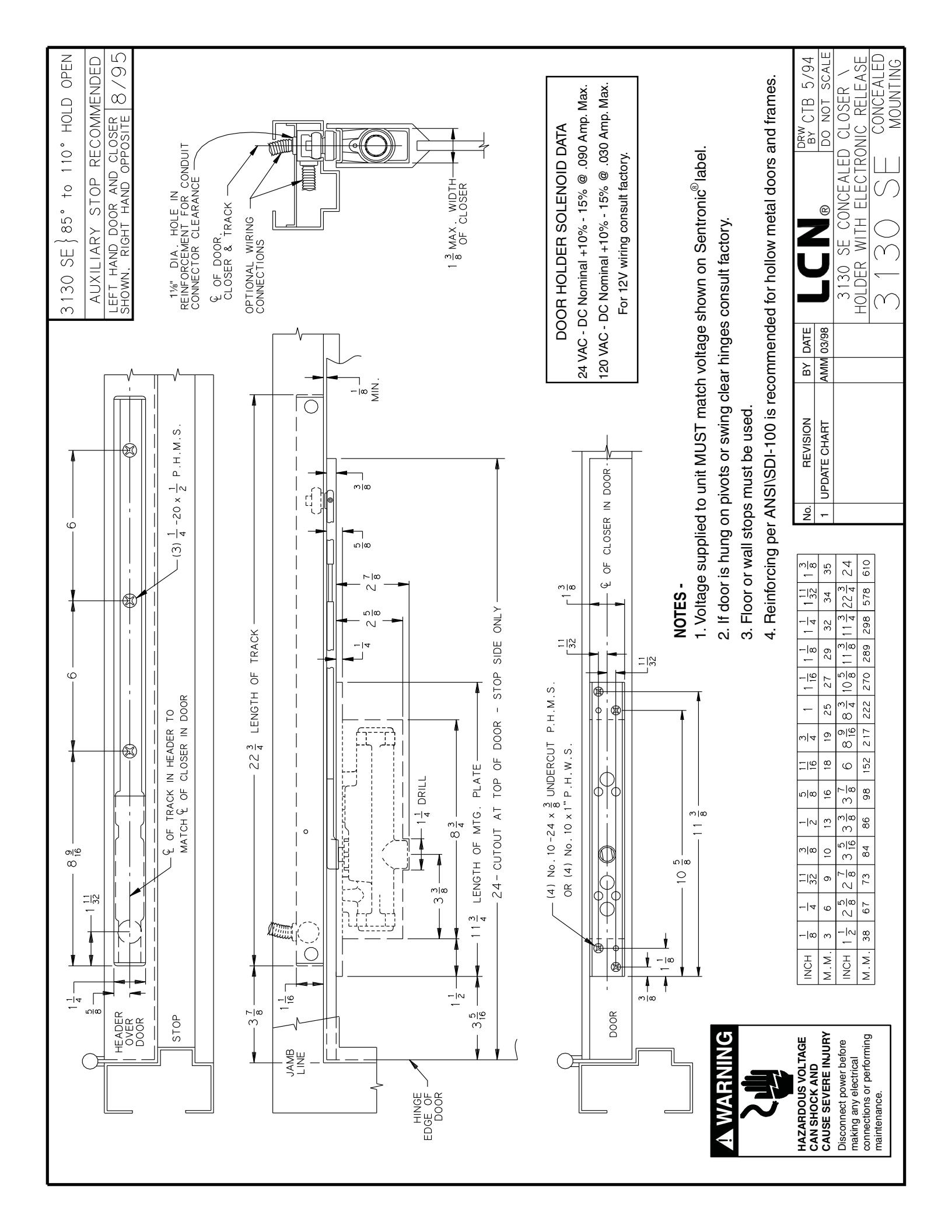
- 1. Closer is handed at factory and must match hand of door. Hand of closer shown on mounting channel.
- 2. Voltage shown on Sentronic cover plate must match voltage supplied to door frame (24V or 120V).
- 3. If door and frame are not prepared for closer and track then prepare in accordance with template on opposite side.
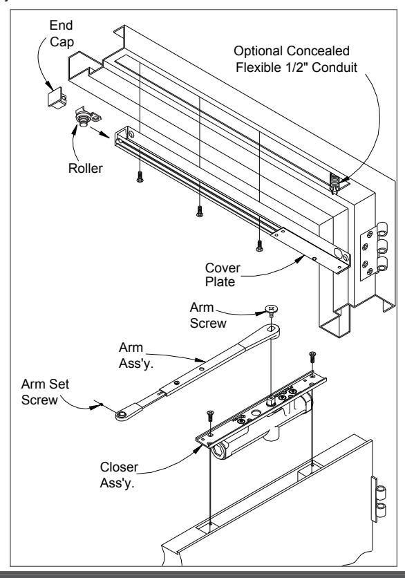
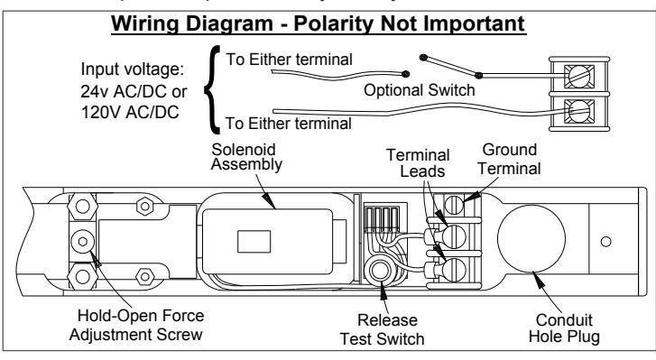
- 4. Remove cover plate from track. Assemble flexible conduit connector to tapped hole provided in top of track. Connect power supply wires to track terminal strip. See wiring diagram below. Insert track into frame and secure with proper screws as shown on opposite side. Replace cover plate, aligning hole with switch.
- 5. Insert closer into cut-out in door and secure with proper screws.
- 6. Place arm on closer shaft and secure with arm screw.
- Loosen set screw in end of arm, open door part way(about 30°), pull arm away from top of door and connect to track roller. Tighten set screw firmly. Open door to hold open position.
- 8. To place door in desired hold open position, remove arm screw in adjustable arm and re-insert arm screw at new location and tighten.
A CAUTION A
Improper installation or regulation may result in personal injury or property damage. Follow all instructions carefully. For questions, contact LCN Closers at: 877-671-7011
Customer Service
1-877-671-7011 www.allegion.com/us
Regulation
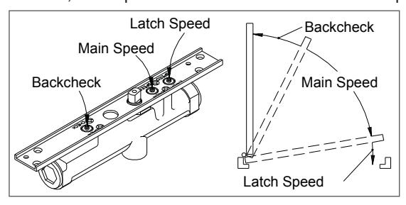
IMPORTANT: The 3130 SE door closer is regulated prior to shipment. If adjustments are necessary, use a 3/32" hex wrench to adjust speed. To slow MAIN SPEED of door turn MAIN SPEED screw clockwise. To slow LATCH SPEED of door turn LATCH SPEED screw clockwise. To increase BACKCHECK turn BACKCHECK screw clockwise. Use lightest BACKCHECK that will retard door opening sufficiently. Do not use an ABRUPT BACKCHECK, nor expect door closer to act as a door stop.
Electrical Checkout
- 1. With power on, open door completely. Door should remain in open position. if door does not stay open check electrical input.
- 2. Push release test switch. Door should close immediately. Open the door to hold-open position and let it remain there.
- 3. System should be checked at frequent intervals It is suggested that step 2 be repeated every 90 days.
Hold Open Force Adjustment
Locate hold-open adjustment screw in diagram above. For greater hold open force, insert socket screw key wrench (included in screwpack) and turn clockwise. To decrease amount of hold open force, turn screw counter-clockwise. Maximum of 4 turns.
A WARNING A
HAZARDOUS VOLTAGE CAN SHOCK AND CAUSE SEVERE INJURY
Disconnect power before making any electrical connections or performing maintenance.

© Allegion 2017 Printed in U.S.A. 18781 Rev. 08/17-k
Conduit Quick Connector
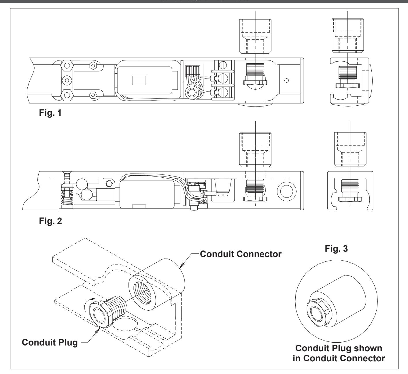
Installation Instructions
- 1a The Conduit Quick Connector and Plug can be found in the closer screwpack.
- 1b The Conduit Quick Connector should be fastened to the 1/2" concealed conduit prior to step 3 on the closer installation instructions.
- 1c During step 3 on the closer installation instructions, make sure that the Conduit Connector is secured flush against the track surface. See option in Fig. 1 below that matches the mounting option selected for track surface. With the track mounted, take the Conduit Plug and slide it through the 1/2" hole in the track. (see Fig.2) Tighten the Plug into the Conduit Connector using a 5/8" wrench, until completely secure, as shown in Fig.3.