LCN 2210DPS Installation Instruction 106931
Open the original PDF document
View PDF

2210DPS Series

Door Closers Installation Instructions
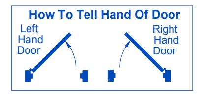
- Make sure hand of closer matches hand of door. Remove finish plates. Hand of closer is printed on the mounting plate label. Hand of closer cannot be reversed. See diagram above to determine hand of door.
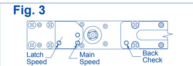
- 1b Prepare and mortise door & frame per template on pg. 4.
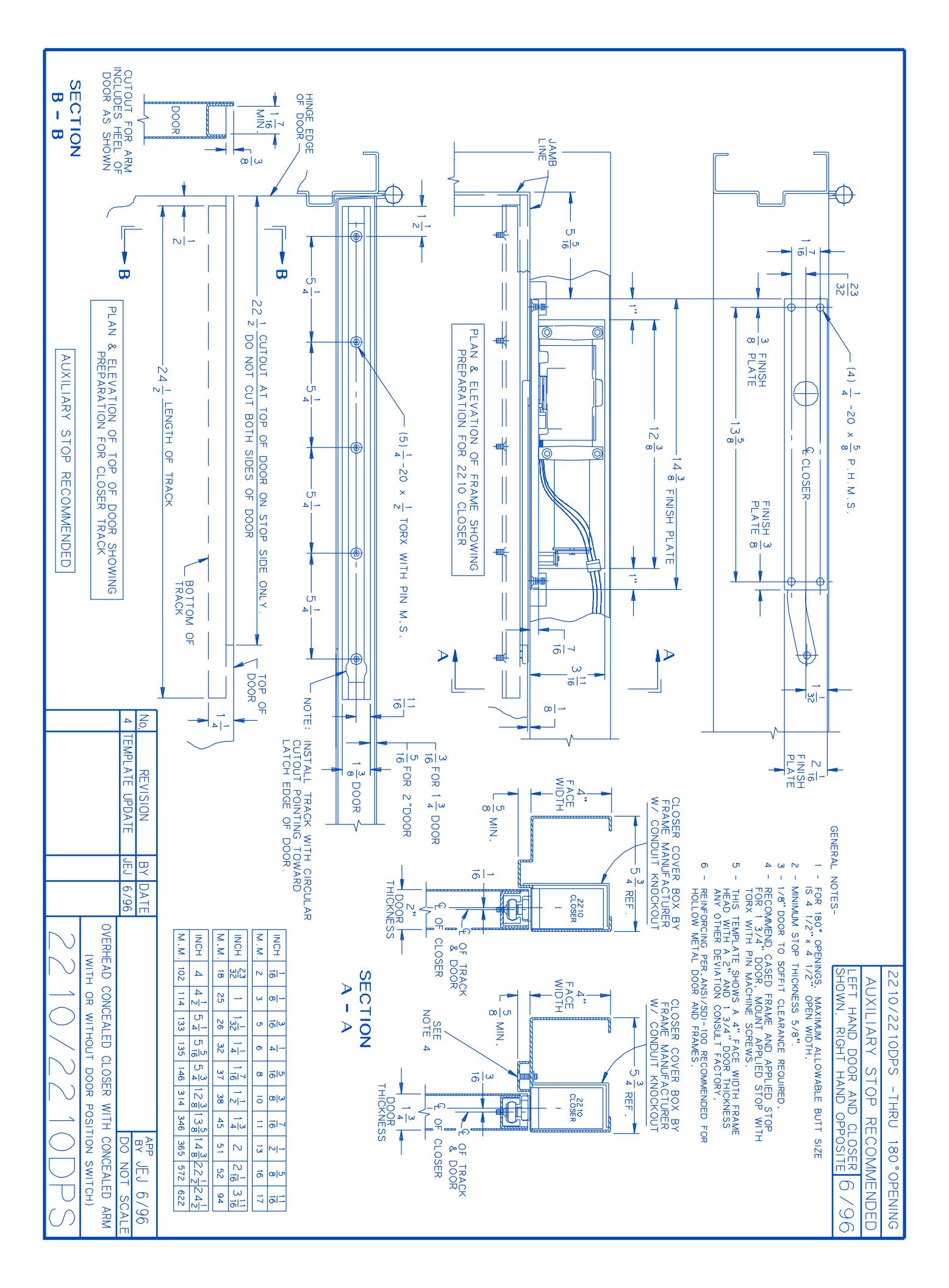
- 1c For 2210DPS: connect wire leads to monitor device as shown in Fig. 2. Do not pinch wires when installing closer into headframe. (Switch contact information with door closed and switch closed.)
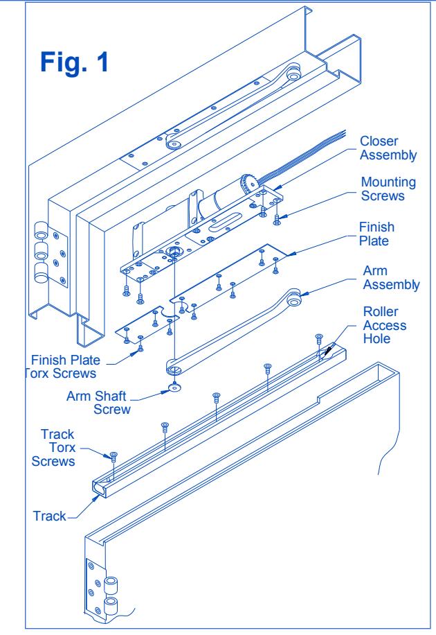
- Install closer in prepared headframe, as shown in Fig. with spring tube pointing away from hinge. Fasten mounting plate to jamb with ½-20 x 5% PHMS provided.
- 1e Install track in door. Roller access hole must be toward latch edge of door, as shown in Fig. 1. Fasten with 20 x TORX MS provided.
- 1f Connect arm assembly to track by placing plastic roller at end of arm into the roller access hole in track. See Fig. 1. Let arm assembly rest on top of installed track.
- 1g To attach arm to closer:
- 1. Open door out of working area.
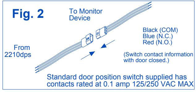
- 2. With a 3/32" hex wrench, turn latch & main speed regulating screws all the way in (clockwise). See Fig. 3. DO NOT FORCE SCREWS.
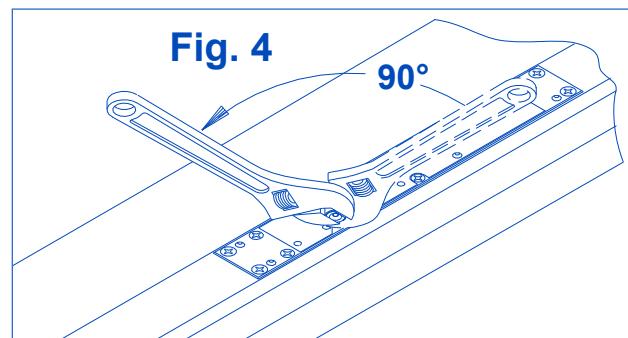
- 3. Using an adjustable wrench, rotate door closer shaft approximately 90°. See Fig. 4. (R.H. clockwise/L.H. counterclockwise).
A CAUTION A
Improper installation or regulation may result in personal injury or property damage. Follow all instructions carefully. For questions contact LCN Closers: 877-671-7011
Customer Service
1-877-671-7011 www.allegion.com/us

© Allegion 2018 Printed in U.S.A. 18363 Rev. 02/18-h
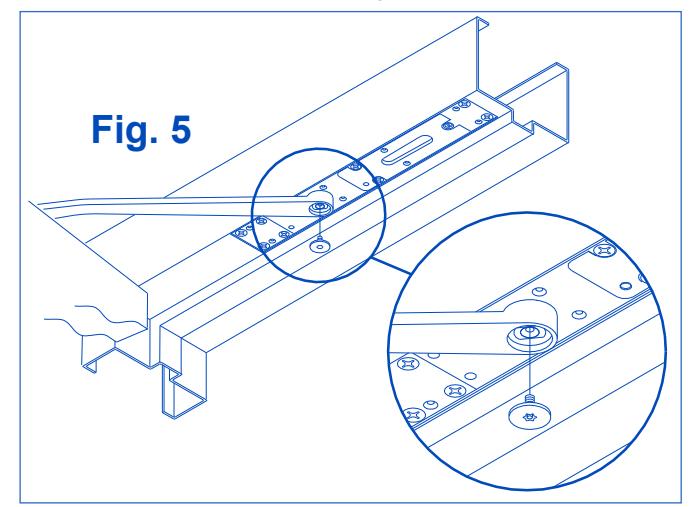
4. With closer shaft now stationary, move the end of the arm to shaft of closer. Slowly move door so hole in arm lines up correctly with closer shaft. Push arm up into position and insert arm shaft screw, as shown in Fig.5.
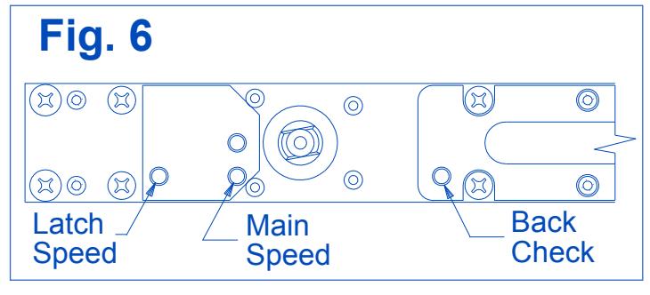
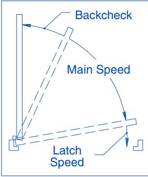
To Regulate Closing Speed & Backcheck: See Fig. 6 below Use a 3/32" hex wrench to re-adjust MAIN & LATCH speed screws (closed in step 7A). Turn both MAIN & LATCH speed screws 2 full turns counterclockwise. Open door and observe closing cycle. A normal closing time from a 90° position is 5 to 7 seconds, equally divided between MAIN & LATCH speeds. If further adjustment is required, turn regulating screws clockwise to SLOW door speed / counterclockwise to INCREASE door speed. BACKCHECK is a feature that slows the speed of door at approximately 70°. To INCREASE force turn BACKCHECK screw clockwise. To REDUCE force turn BACKCHECK screw counterclockwise. Do not use an abrupt BACKCHECK setting, nor expect closer to act as a door stop!
1i For 2210DPS: Signal Response Point Verification
If door silencers are to be used, they should be installed prior to this step. Close the door slowly and note where the switch response signal occurs. The factory setting should provide a signal response between 1/4" & 3/4" off the stop for a 36" door.
Only if a different signaling point is necessary, perform steps a - c using a No. 3 Phillips screwdriver (5/16" shank). If the switch is giving an "open" signal when the door is fully closed, follow steps 9D through 9F.
To adjust the signaling point for the door nearer to the closed position:
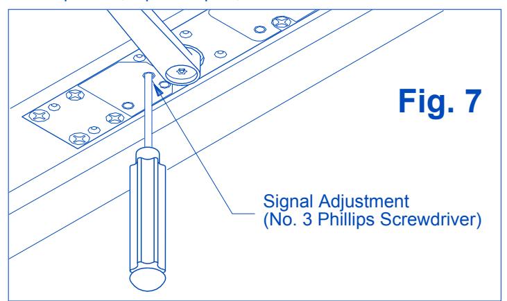
- a. Open the door approximately 20°, or enough to access the signal adjustment hole in mounting plate (See Fig. 7, below). Prevent door from moving during the adjustment. Insert the No. 3 Phillips screwdriver into the signal adjustment hole to engage the trigger gear.
- For Right Hand Door: turn the screwdriver <u>clockwise</u> VERY SLIGHTLY
For Left Hand Door: turn the screwdriver <u>counterclockwise</u> VERY SLIGHTLY
c. REMOVE SCREWDRIVER BEFORE ALLOWING DOOR TO MOVE. Allow the door to close completely. Check the signal activation point. If still too far from the "door closed" position, repeat steps a, b & c.
To adjust the signaling point for the door farther from the closed position:
- d. Open the door approximately 20°, or enough to access the signal adjustment hole in mounting plate (See Fig. 7, on previous page). Prevent door from moving during the adjustment. Insert the No. 3 Phillips screwdriver into the signal adjustment hole to engage the trigger gear.
- e. For Right Hand Door: turn the screwdriver counterclockwise VERY SLIGHTLY For Left Hand Door: turn the screwdriver clockwise VERY SLIGHTLY
- f. REMOVE SCREWDRIVER BEFORE ALLOWING DOOR TO MOVE. Allow the door to close completely. Check the signal activation point. If still too close to the "door closed" position, repeat steps d, e & f.
1j CLOSING POWER ADJUSTMENT:
Depending on width of door, the 2210DPS has been ordered as one of three sizes: 2213, 2214 or 2215. Determine closer size from either label on box or UL label on mounting plate.
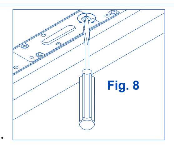
Adjustment can be made with a flat head screwdriver (see Fig. 8). Adjustment range for each size is as follows:
2213: Closer is shipped at minimum closing power. If MORE closing power is required, turn adjusting screw counterclockwise, but not more than 36 full turns. DO NOT turn adjusting screw clockwise.
- 2214: If MORE power is required, turn adjusting screw counterclockwise , but not more than 18 full turns. If LESS power is required, turn adjusting screw clockwise , but not more than 18 full turns. Do not turn adjusting screw more than 18 full turns in either direction.
- 2215: Closer is shipped at maximum closing power. If LESS power is required, turn adjusting screw clockwise, but not more than 36 full Turns. Do not turn adjusting screw counterclockwise.
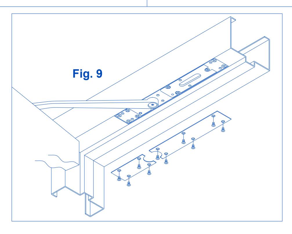
1k Once proper operation has been verified, secure finish plates with No. 10-24 x 3/8" Torx security screws, as shown in Fig. 9 below.