Kaba-Mas Electromechanical Government Security Locks X 07 Installation Guide
Open the original PDF document
View PDFINSTALLATION INSTRUCTIONS
FOR THE X-07/CEX-07 HIGH SECURITY ELECTRONIC LOCK TYPE 1F

Table of Contents
|
INTRODUCTION
3 |
|
|---|---|
|
BASIC TOOLS AND MATERIALS NEEDED
3 |
|
|
LOCK PARTS FOR INSTALLATION
4 |
|
|
INSTALLATION KIT CONTENTS
4 |
|
|
TEMPLATE
5 |
|
| PREPARATION FOR NEW INSTALLATION OF THE LOCK | 6 |
|
INSTALLATION
7 |
|
|
INSTALLATION OF THE LOCK
7 |
|
|
INSTALLATION OF THE DIAL RING
8 |
|
|
INSTALLATION OF THE TUBES AND SPINDLE
10 |
|
|
INSTALLATION OF THE DIAL HUB AND DIAL
18 |
|
|
INSTALLATION COMPLETION CHECKLIST
20 |
|
| RESETTING COVERT ENTRY AND COVERT ENTRY | |
|
COMBINATION CHANGE
21 |
INTRODUCTION
Please read all instructions before you install and use your Model X-07 lock. This will help you avoid unnecessary costs and concerns resulting from improper installation.
BASIC TOOLS AND MATERIALS NEEDED
- 1. Small Phillip's head screwdriver (#0)
- 2. Medium Phillip's head screwdriver (#1/#2)
- 3. Standard hacksaw (32 teeth/inch)
- 4. Small flat file
- 5. Small vise
Recommended, but not required:
- 6. Torque screwdriver (30 inch-pound capacity), or
- 7 Standard torque wrench with screwdriver bits
Note: See table of recommended torques for the various X-07 lock screws.
All other necessary tools and materials are provided.
| TABLE OF RECOMMENDED TORQUES FOR THE VARIOUS X-07 LOCK SCREWS | ||||
|---|---|---|---|---|
| Applications | P/N | Screw Size | Torque (In.Lb.) | |
| Slide Retainer | 105014 | 1-64 | 1.0 to 1.5 | |
| Lever | 105017 | 1/2-32 | 15.0 to 18.0 | |
| Motor Mounting | 105021 | 2-56 | 2.5 to 3.5 | |
| Cover PCB Mounting | 105021 | 2-56 | 2.5 to 3.5 | |
| Dial Ring PCB Mounting | 105030 | 6-32 | 9.0 to 11.0 | |
| Lock Case Cover | 105030 | 6-32 | 9.0 to 11.0 | |
| Dial Ring Mounting | 105034/105158 | 8-32 | 17.0 to 20.0 | |
| Dial Ring Cover | 105034 | 8-32 | 17.0 to 20.0 | |
| Spindle | 105219 | 5-40 | 14.0 to 16.0 | |
| Lock Case Mounting | 105046/105195 | 1/4-20 | 25.0 to 30.0 | |
| Dial Hub Set Screw | 105057 | 8-32 | 17.0 to 20.0 | |
| Tube Retainer (D.R.) Mounting | 105059 | 4-40 | 4.0 to 5.0 | |
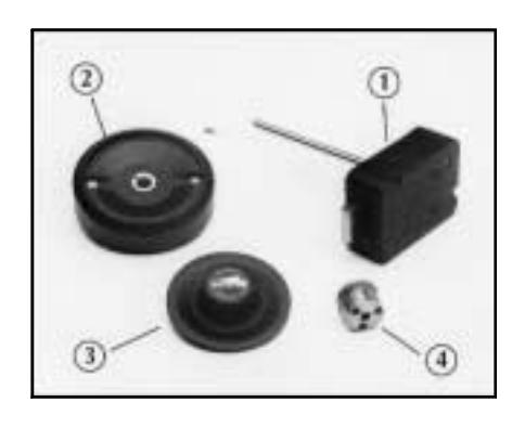
LOCK PARTS FOR INSTALLATION
- 1. Lock assembly
- 2. Dial ring assembly
- 3. Dial assembly
- 4. Dial hub assembly
INSTALLATION KIT CONTENTS
- 1. Lock assembly attaching screws (4)
- 2. Dial ring assembly attaching screws (2)
- 3. Tube, inner
- 4. Tube, outer
- 5. Blade, saw (52 teeth/inch)
- 6. Handle, saw
- 7. Stone, tube deburr
- 8. Gage, tube cut-off
- 9. Gage, dial hub locating
- 10.Hexkey (5/64")
- 11. Lubricant
- 12.Rubber vise clamp

TEMPLATE
A template is provided as an aid for locating, drilling, and tapping the lock case and dial ring mounting screw holes relative to the spindle hole. Since the lock is designed to fit most industry standard container lock mounting screw hole patterns, the need to use this template should be minimal.
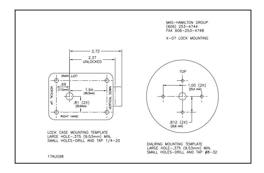
Note: The above template is NOT Actual Size. Do Not Use for locating, drilling, and tapping the lock. A Template of actual size is included with the lock for installation purposes.
PREPARATION FOR NEW INSTALLATION OF THE LOCK
- 1. Use the template to establish the exact relative locations of all of the necessary mounting holes for the lock case and the dial ring, when necessary.
- 2. The lock case mounting screws require drilled and tapped 1/4-20 screw holes.
- 3. The dial ring mounting screws require drilled and tapped #8-32 screw holes.
- 4. The spindle hole must be 0.375 inch diameter, minimum.
INSTALLATION
INSTALLATION OF THE LOCK
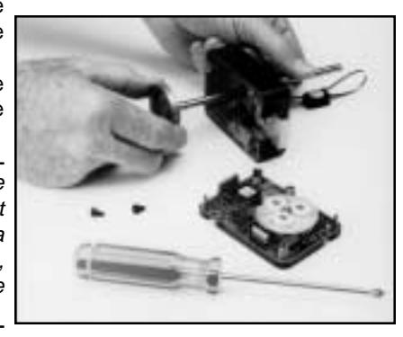
- 1. Remove the two screws from the lock assembly cover and remove the cover.
- 2. Remove the drive cam/spindle assembly from the lock case assembly.
Note: It is possible to order some locks from the factory with pre-cut tubes and spindle. If you have a lock installation with pre-cut parts, you may skip to "Installation of the dial ring".
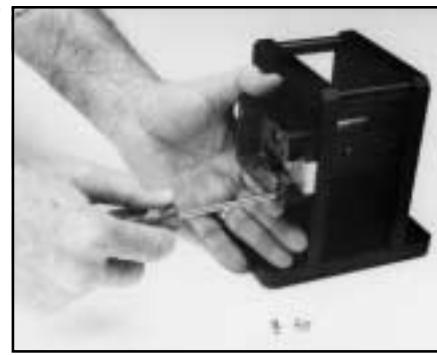
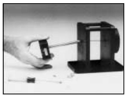
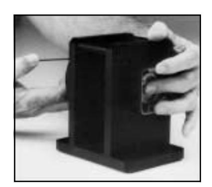
- 3. Feed the cables through the outer (larger) tube.
- 4. Seat the tube into position on the tube retainer on the back of the lock case assembly. (See Figure 1) Be careful to keep the cables pulled taut while seating the tube to avoid pinching damage to them.

Figure 1 Tube-Cable Assembly Relationships
5. Carefully guide the outer tube (keeping it in place on the tube retainer) through the container wall so that the outer tube and the cables are easily accessible at the outside wall of the container. On some containers, the only way to do this is to retract the bolt. If this is the case, remember to extend the bolt and slide to their fullest extension after installing the lock case mounting screws and before continuing.
Note: Another outer tube inserted from the dial ring side would be very helpful as a guide for greater ease in feeding the cables through the container wall.
- 6. Attach the lock case assembly to the container wall using the lock case mounting screws.
- 7. While holding the outer tube against its seat on the tube retainer, move the lock case assembly around until the tube is reasonably centered in the hole in the outside container wall.
- 8. Tighten the lock case mounting screws to hold the lock case firmly in place.
INSTALLATION OF THE DIAL RING
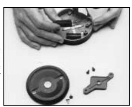
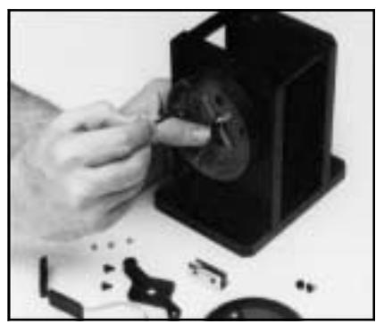
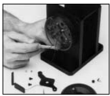
- 1. Remove the two screws from the dial ring assembly cover and remove the cover.
- 2. Remove the two screws from the cable/tube retainer and remove it.
- 3. Work the ZIF seal out of its holder and remove the LCD from the dial ring.
4. Remove the 4 screws from the tube retainer and remove the tube retainer and the ZIF seal holder.
Note: With pre-cut tubes this step is not necessary. In this case, the dial ring can be mounted with the tube retainer already in place.
- 5. Guide the cables and the outer tube through the center hole of the dial ring, so that they are both easily accessible inside the dial ring.
- 6. Set the dial ring assembly in place against the outside container wall while entering the tube in the center hole of the dial ring. Insert and tighten the two mounting screws.
INSTALLATION OF THE OUTER (LARGER) AND INNER (SMALLER) TUBES AND SPINDLE
Note: If you have a lock installation with pre-cut parts, you may skip to step 9.
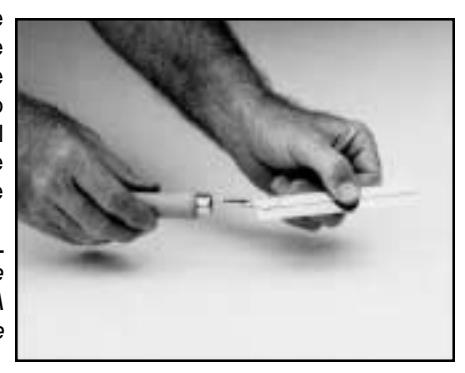
- 1. Place the tube cut-off gage over the end of the outer tube and against the inside wall of the dial ring.
- 2. Make sure that the outer tube is properly seated on the lock case tube retainer.
- 3. While holding the outer tube firmly in its seated position and with the tube cut-off gage pressed against the dial ring wall, mark the tube for cutting.
- 4. Remove the lock case assembly from the container and remove the outer tube for cutting.
- 5. Assemble the saw blade in to the wooden saw handle provided. When the saw frame neck is fully seated into the handle, grip the saw frame (preferably in a vise) and tap the handle another 1/8" to 1/4" onto the saw frame neck. This will reduce the tendency of the handle to turn on the saw frame when sawing.
Note: This saw is intended to be used only to cut the tubes. A standard hacksaw should be used to cut the spindle.
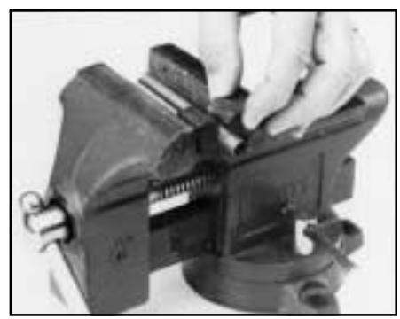
6. Insert the tube to be cut into the rubber vise clamp (provided). Then firmly clamp the rubber vise clamp in a vise. Use the saw to cut the tube where marked. Be careful to keep the cut as straight as possible. Remember the saw only cuts when pushing. Trying to cut while pulling may pull the handle off the saw blade.
Warning: The end of the large tube that is to be discarded must be from the plain (unflared) end of the tube. The end of the small tube that is to be discarded must be from the plain (unnotched) end of the tube.
- 7. Use the piece cut from the outer tube to measure and mark the inner (smaller) tube. The same amount will be cut from each tube. The rubber vise clamp should also be used while cutting.
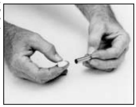
- 8. The inside of the tubes must be deburred after cutting. Use the stone which is provided for this purpose.
- 9. Place the inner tube (smaller) into the lock case tube retainer. Make sure that the cutout in the tube aligns with the cables and allows the inner tube to seat completely in the tube retainer.
- 10.Feed the cables through the outer tube while placing the outer tube over the inner tube.
Seat the outer tube completely onto the tube retainer. (See Figure 1.) Be careful to keep the cables pulled taut while seating the outer tube to avoid pinching damage to them.
11. Carefully guide the tubes and cables through the walls of the container, making sure that the tubes remain properly seated on the tube retainer. (See Installation of the Lock step #5.) Position the lock case assembly against the inner wall of the container. Insert and tighten the mounting screws to hold the lock case assembly firmly in place.
Note: Placing the outer tube into position in the container wall first and feeding the cables and the inner tube through it, will make assembly easier on the thicker walled containers.
12.Place the tube retainer spring into the dial ring with its raised center portion facing outward. Feed the cables through its center hole and position it over the tubes so the small tube slides through its center hole and it rests against the end of the larger tube.
Caution: Do not turn the retainer once it is placed over the tubes.
- 13.Insert the upper left screw.
- 14. Place the ZIF seal holder in the lower right quadrant of the dial ring with its tab positioned under the tube retainer spring. Insert a screw through both parts and start it into the hole.
- 15.Rotate the seal holder clockwise to assure approximately 1/8 inch clearance between it and the dial ring at the bottom. Tighten the screw.
- 16.Insert the other two screws and tighten them all.
17.Open the ZIF (Zero Insertion Force) seal cover and move the ZIF connector locking actuators outward to their open position. (See Figure 2.)
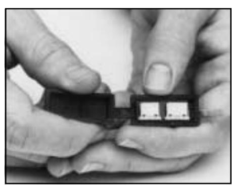
Figure 2 Plugging Cables Into the ZIF Connector
- 18.Plug the cables into the ZIF connectors. The bright metal tabs on the cables should be facing toward the circuit board to which the ZIF connectors are attached.
- 19.The 5-conductor cable goes into the ZIF connector nearest the cable connecting to the LCD. The 4-conductor cable goes into the ZIF connector away from the cable connecting to the LCD. Close the ZIF locking actuators to lock the cables in place.
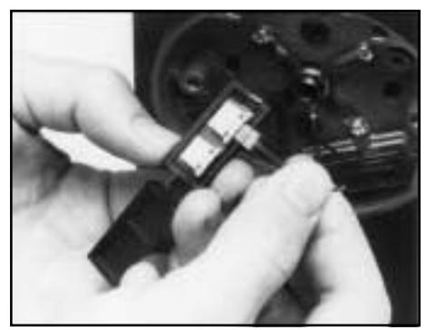
Note: The 3/16 inch long darkened section of the cable under the bright metal tabs should be completely inside the ZIF connector when properly installed.
20.Place the LCD into the dial ring. Note that the cable coming out of the LCD is nearer one edge than the other. The side nearest the cable should face outward, away from the dial ring, when installed.

- 21.Close the ZIF seal. Rotate the seal into the seal holder so its beveled side with the cable clearance slots is facing outward and toward the center of the dial ring. The cables must exit the top of the seal and lay in the clearance slots going toward the center of the dial ring.
- 22.Replace the cable/tube retainer, being careful to position the cables underneath so that they will not be pinched or damaged in any way. Insert and tighten the (2) screws.
- 23.Install the dial ring cover and tighten the cover screws.
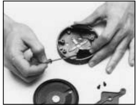
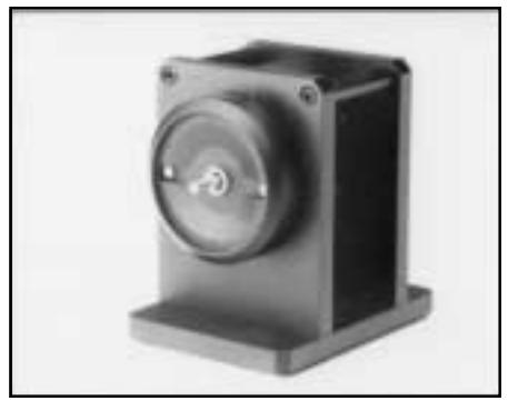
- 24.Install the drive cam/spindle assembly into the lock case assembly until the drive cam is properly seated and the spindle extends through the dial ring cover.
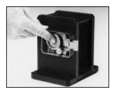
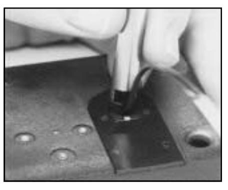
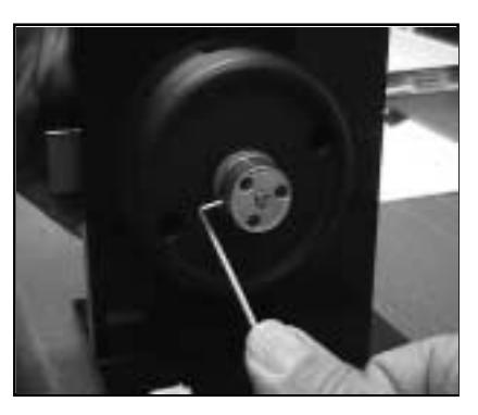
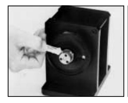
Correct Gear Position
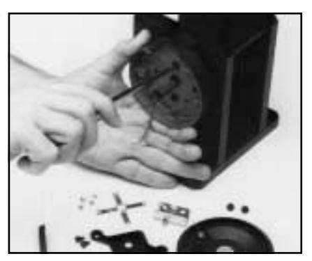
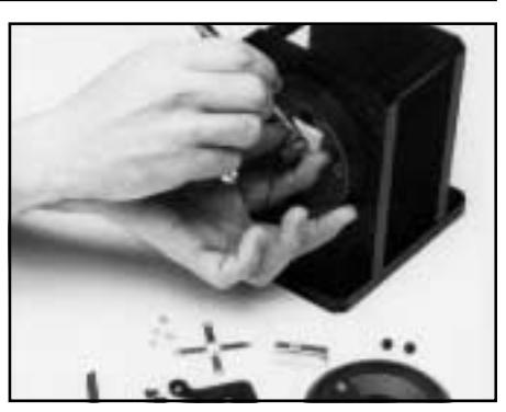
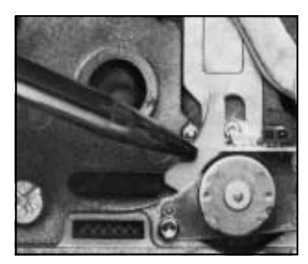
Note: To avoid unnecessary damage - always make sure that the motor gear is in its proper detent position when inserting the drive cam/spindle assembly. If it is not, a pencil may be used to move it to the proper position.
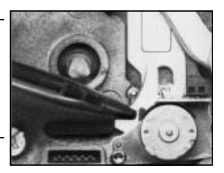
Incorrect Gear Position
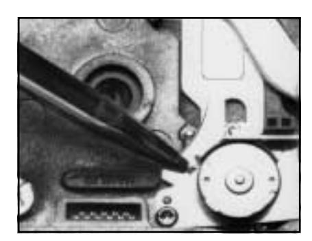
Incorrect Gear Position
25.Check the spindle for freedom to rotate without scraping. If scraping does occur, loosen the dial ring mounting screws and center the dial ring around the spindle until the scraping is eliminated. It may also be necessary to adjust the positioning of the lock case assembly.
-
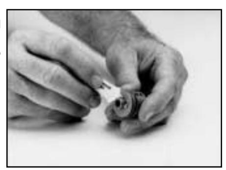
26.Place the dial hub assembly onto the spindle. Push the dial hub tightly against the dial ring
- cover while pulling on the spindle and lightly tighten one set screw against the spindle.
- 27. Using a hacksaw,cut the spindle flush with the dial hub assembly. File spindle if necessary to remove burrs and insure proper fit in dial.
Caution: Do not lubricate the lock except as directed by these installation instructions. Proper lubrication of the lock has been performed at the factory.
INSTALLATION OF THE DIAL HUB AND DIAL
- 1. Loosen the set screw and remove the hub.
- 2. Apply lubricant to the hub bearing surface.
3. While holding the drive cam in its proper position in the lock case assembly inside the container, push the dial hub assembly onto the spindle.
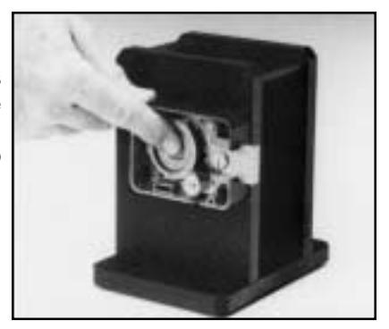
4. Place the dial hub locating gauge over the spindle and between the dial hub assembly and the bushing in the dial ring cover. This sets up an initial .010" end play.
Recommendation: Make a bend in the dial hub locating gauge at its midpoint. This will keep it from acting as a spring as the hub is positioned for locking to the spindle.

5. While maintaining a constant pressure on the dial hub and the drive cam assemblies, pushing them toward each other, SECURELY tighten the set screws in the dial hub assembly to 17- 20 inches/ pound of torque ( a minimum of 1" deflection of the handle of the hexkey). Remove the dial hub locating gauge.
Caution: Tighten in a downward motion in case the hexkey should break.
6. Apply lubricant generously to the retaining ring on the dial hub assembly and position the retaining ring so that an equal amount of it is consistently exposed around the hub. Also, apply grease from the lubricant tube to the entire ramp area just inside the back of the dial.

| Note: |
Make sure the ends of the
retaining ring bracket the set screws in the hub and that an equal amount of the retaining ring is exposed around the hub so the dial can slide easily into place on the hub without interference from the retaining ring. |
|
|---|---|---|
| 7. |
Carefully place the dial over the dial
hub assembly and apply pressure to the dial until the retaining ring seats in the dial. |
|
| assembly. |
Note: You should not be able to pull
the dial away from the dial hub |
|
| 8. |
Replace the lock case cover
assembly. Insert and tighten the (2) cover screws. |
INSTALLATION COMPLETION CHECKLIST
- 1. Does the dial turn freely without scraping or binding?
- 2. Have all screws been securely tightened?
- 3. Dial the combination (it has been factory set to 50-LEFT, 25-RIGHT, 50- LEFT). Your Model X-07 should turn freely without scraping or rubbing and should open when the correct combination has been dialed. (See General Information: Dialing Instructions-Single Combination Mode). If the lock is a CEX-07, it will display CE when it is powered up and will not operate until the combination is reset. Use the following procedure to reset the combination.
RESETTING COVERT ENTRY AND COVERT ENTRY COMBINATION CHANGE
This procedure works only if the lock is powered down when dialing to the right (CW), with the change key out of the lock.
Dialing to the right (CW) on lock startup will display the open counter. Once the open counter is displayed, insert the change key. If there is a covert entry or the change key is in, continuing to dial to the right will result in dialing an ID. The ID is selected when the direction is reversed. The lock level is not displayed when the change key has been inserted, or there has been a covert entry. Instead, the numbers for selecting an ID are displayed.
Dial to 99 and reverse directions, After reversing directions, dial the covert entry combo starting to the left as with the other combinations. If the combination is correct, the covert entry condition will be reset.
The default covert entry combination is 50 25 50.
To change the covert entry combination, dial to the right until the open counter is displayed. The change key needs to be inserted during the open counter display. If it is in before the open counter display it will not be recognized. Begin by dialing right to ID 99 and then dialing the current covert entry combination. If the combination is correct, you will be able to enter and confirm the new covert entry combo the same as changing a single normal combination. The lock will open upon completing the combination change.
Document Number 001.123 Rev. D 11/98 Converted to Acrobat 08/00
Notice: The information in this manual is subject to change without notice and does not represent a commitment on the part of Mas-Hamilton Group (MHG). MHG shall not be liable for technical errors or omissions contained herein; not for incidental or consequential damages resulting from the furnishing, performance or use of this material.
© 1997, 1998 Mas-Hamilton Group®
All rights reserved

805-D Newtown Circle, Lexington, KY 40511 Phone (888) 950-4715 or (859) 253-4744 FAX (859) 281-5766 24-hour Technical Support: (800) 950-4744