Jackson Overhead Concealed Door Closer Center Hung and Offset Installation Instructions
Open the original PDF document
View PDFINSTALLATION INSTRUCTIONS
CRL JACKSON OVERHEAD CONCEALED DOOR CLOSER CENTER HUNG AND OFFSET

Phone: (800) 421-6144 • Fax: (800) 262-3299 crlaurence.com • usalum.com • crl-arch.com
PRODUCT DESCRIPTION
Jackson Overhead Concealed Door Closers (OHC) are available from C.R. Laurence as closer bodies only or as standard packages for center hung and offset door installations. The standard packages include the closer mechanism, mounting brackets, arms, and pivots. OHC's are divided into three groups:
Standard OHC's (Brown) are offered with four (4) fixed spring sizes for doors from 2'6" to 4'0" wide (see chart on page 14). Other options include 90 degree and 105 degree hold open and non-hold open versions.
Grade 1 OHC's (Black) have been tested to ANSI Grade 1 Standards (2 million cycles). They feature a valve adjustable hydraulic backcheck and are available in 90 degree and 105 degree hold open and non-hold open models.
Adjustable OHC's (Blue) allow the opening spring force to be adjusted from 4.5 lbs. to 15 lbs. Adjustability is especially useful when attempting to balance between stack pressure and ADA requirements. The standard factory adjusted spring pressure is set to the size "Light Duty" and is intended for a 7'0" x 3'0" door. To increase the spring force by one size, turn the adjustment screw four (4) turns clockwise. Adjustable OHC's are also available in 90 degree and 105 degree hold open and non-hold open models.
All Jackson OHC's are non-handed, double-acting, and work with center hung and offset applications. Additionally, the body size and mounting holes of standard and adjustable OHC's are identical and interchangeable with one another.
CRL JACKSON OVERHEAD CONCEALED DOOR CLOSER
CONTENTS
|
Jackson Overhead Concealed Door Closer |
04-06 |
|---|---|
|
Center Pivot Door Typical Installation Series 400, 450, and 451
|
04 |
|
Instructions and Adjustments
|
05 |
|
Closer Located in Header
|
06 |
|
Frame Unit for Center-Hung Door with Overhead Concealed Door Closer
|
07 |
|
Center Hung Installation, Door/Threshold Preparation
|
08 |
|
Jackson Overhead Concealed Door Closer, Side Load Center Pivot Door
|
09 |
| Center-Hung Door Installation with a Side Load Top Arm | 10-11 |
| Jackson Overhead Concealed Door Closer, End Load Center Pivot Door | 12 |
| Center-Hung Installation | 13-15 |
|
Top Arm Assemblies
|
13 |
|
Overhead Concealed Door Closers
|
14 |
| Pivots | 15 |
|
Jackson Overhead Concealed Door Closer for Butt Hinge Door
|
16 |
|
Jackson Overhead Concealed Door Closer for Offset Pivot Door, 90º Swing
|
17 |
|
Jackson Overhead Concealed Door Closer for Offset Pivot Door, 105º Swing
|
18 |
| Offset Pivot Installation | 19-20 |
|
Header for Jackson Overhead Concealed Door Closer With Offset Arm
|
21 |
| Jackson Overhead Concealed Door Closer for Offset Pivot Door | 22 |
| Offset Closer Arm Installation | 23-24 |
|
Offset Arm/Channel Assemblies (Charts)
|
25 |
|
Center Pivot-Top Portion for Floor Mounted Closer
|
26 |
|
Frame Unit for Butt Hung Door with Surface Mounted Closer
|
27 |
JACKSON OVERHEAD CONCEALED DOOR CLOSER
CENTER PIVOT DOOR TYPICAL INSTALLATION SERIES 400, 450, AND 451 FABRICATED DOOR HEADER
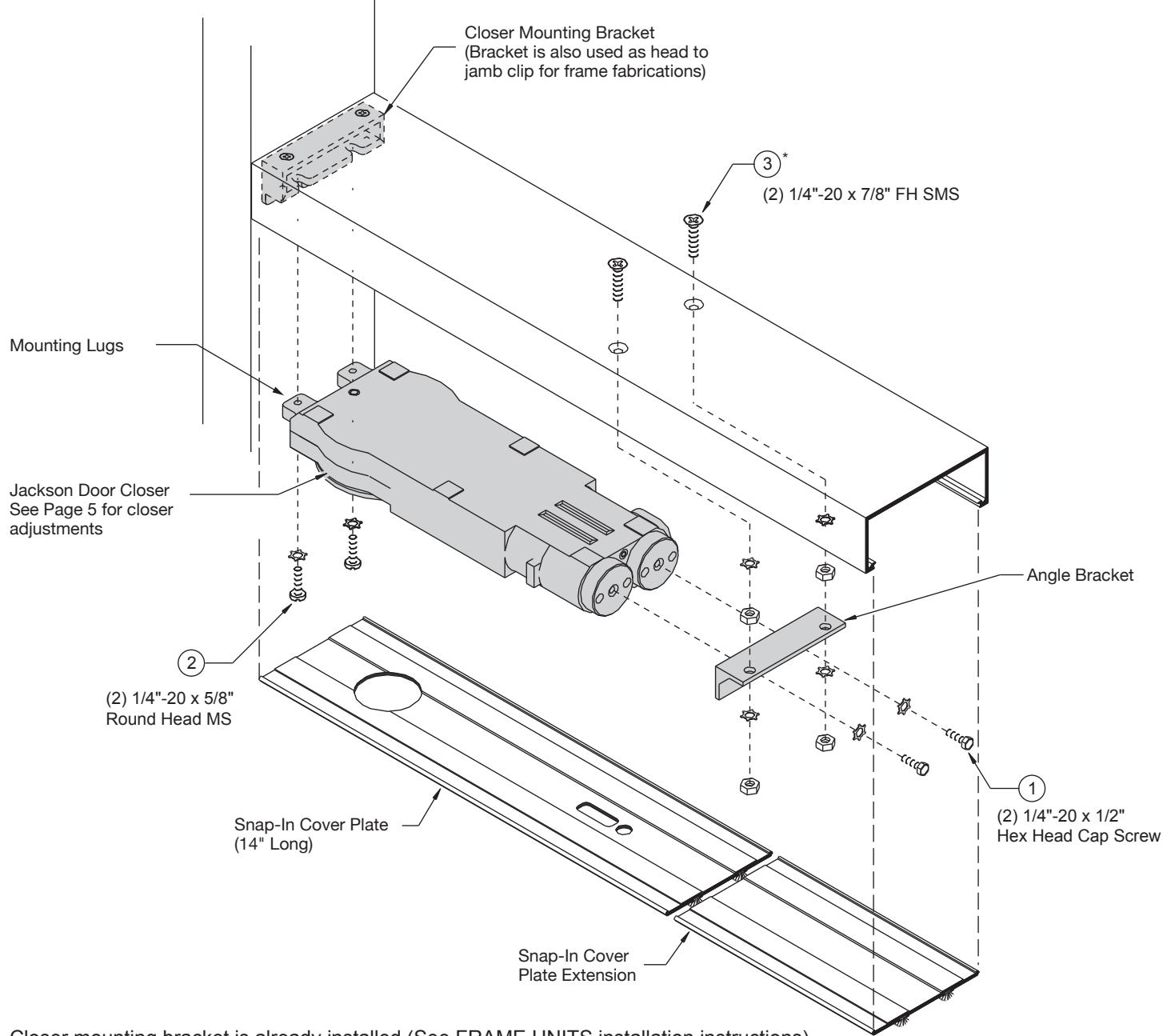
Closer mounting bracket is already installed (See FRAME UNITS installation instructions).
- 1. Mount angle bracket to door closer with (2) 1/4"-20 Hex Head Cap screw and (2) lock washers.
- 2. Install (2) 1/4"-20 x 5/8" Round Head MS into lugs of closer. Do not tighten screws.
- 3. Install (2) 1/4"-20 x 7/8" FH SMS* with (2) 1/4"-20 nuts and washers in header.
- 4. Insert closer lugs into mounting bracket slot at an angle and raise closer opposite end to align mounting screws with angle bracket holes. Secure bracket to mounting screws using (2) nuts and washers.
- 5. Tighten Round Head Screws.
- 6. Snap-In Cover Plate.
*For 2" x 4-1/2" header, longer screws are provided.
JACKSON OVERHEAD CONCEALED DOOR CLOSER
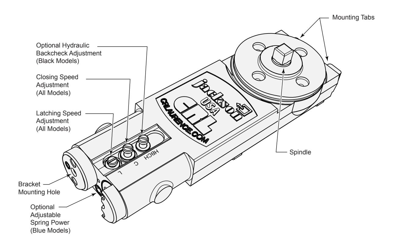
INSTRUCTIONS AND ADJUSTMENTS
IMPORTANT: PLEASE READ BEFORE PROCEEDING . Observe all safety warnings. Always wear proper eye protection and appropriate safety equipment. Always place a safety block between the door and the jamb to prevent the door from closing while making adjustments. The closer contains springs compressed under high load and has no user serviceable internal components. Do not attempt to remove the covers or otherwise open the closer in any manner.
The closer has been fully tested and adjusted at the factory. The closing and latching speeds have been pre-set to achieve a 6 to 8 second closing cycle. The optional hydraulic backcheck has not been factory pre-set. After installation, cycle the door 10 or more times from the maximum open position to the full closed position prior to making final adjustments.
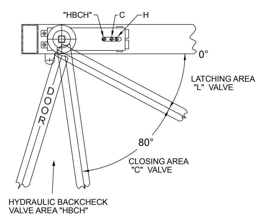
To increase either the closing or latching speeds, turn the appropriate adjustment valve counter-clockwise. To decrease either the closing or latching speeds, turn the appropriate adjustment valve clockwise. Set the latching speed (Valve "L") first, then set the closing speed (Valve "C"). Check and readjust if necessary.
Hydraulic Backcheck (if so equipped) turn the adjustment valve clockwise to increase backcheck resistance which dampens and slows the momentum of the door when opened with excessive force. Decrease resistance by turning the adjustment valve counter-clockwise. The adjustment valve must not be adjusted so that the backcheck function is used as a rigid backstop. Using the backcheck as a rigid backstop may cause damage to the closer or door.
Adjustable Spring Power (if so equipped) the adjustable spring power has been factory set to Size 2. To increase the spring power, turn the adjuster clockwise. To decrease, turn the adjuster counter-clockwise. Typical door opening force adjusts at the rate of approximately 1 pound of force (4.5 N) for each 3 to 4 revolutions of the adjuster.
IMPORTANT: Do not attempt to adjust the spring power with the door open beyond 20 degrees from fully closed.
WARNING: Neither the standard internal back stop nor the optional backcheck are to be used as the primary door stop. An auxiliary floor or overhead door stop is always recommended to prevent structural interference and possible door and closer damage.
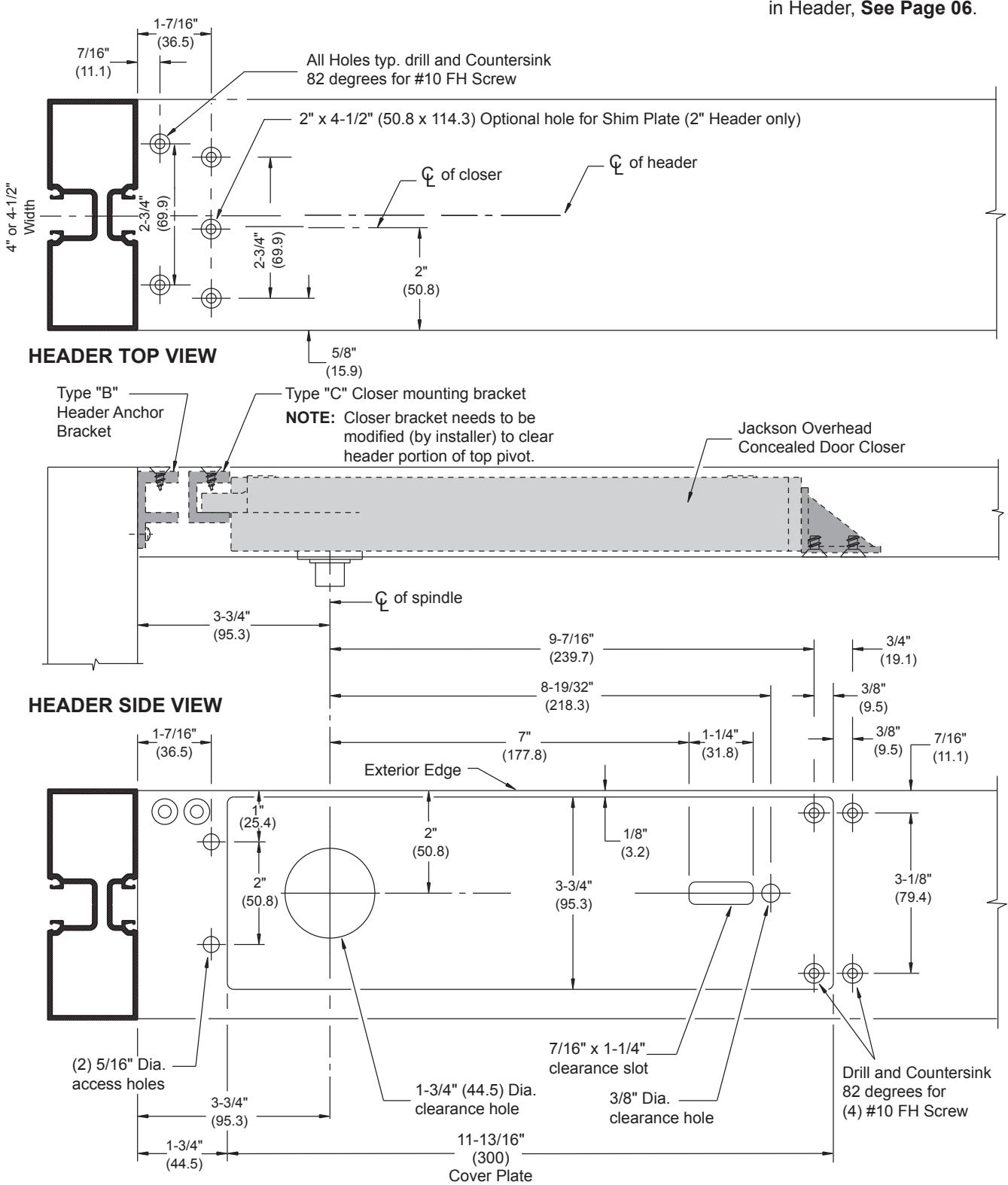
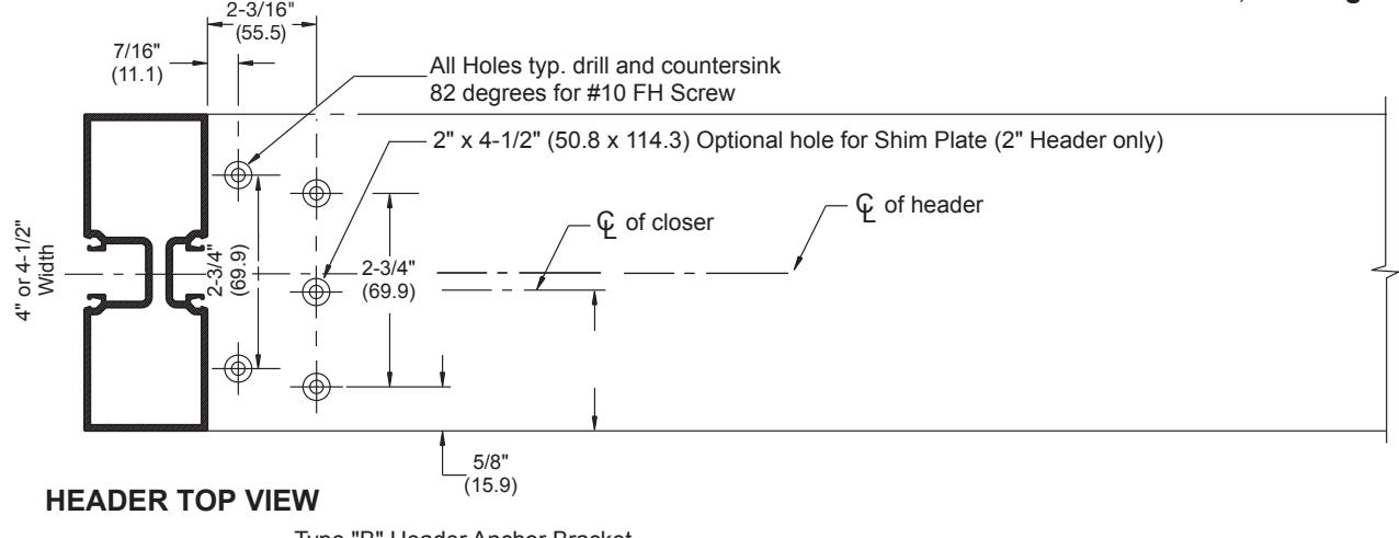
CLOSER LOCATED IN HEADER JACKSON OVERHEAD CONCEALED DOOR CLOSER
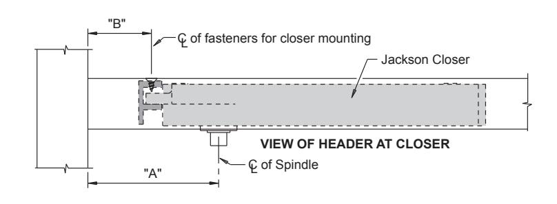
| DOOR TYPE |
HOLD
OPEN |
DIMENSION
"A" |
DIMENSION
"B" |
|---|---|---|---|
| CENTER PIVOT | 90º OR 105º |
2-3/4"
(69.9) |
7/16"
(11.1) |
| OFFSET PIVOT | 105º |
4-1/2"
(114.3) |
2-3/16"
(55.6) |
| (0P400) | 90º |
3-3/4"
(95.3) |
1-7/16"
(36.5) |
| 105º |
3-3/4"
(95.3) |
1-7/16"
(36.5) |
|
| BUTT HINGES | 90º |
2-7/8"
(73.0) |
9/16"
(14.3) |
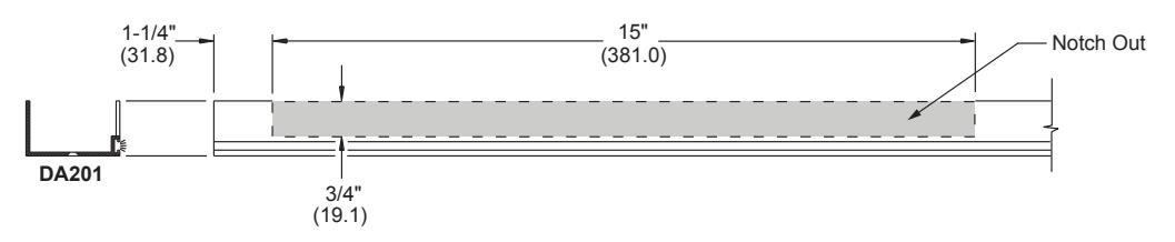
SLIDE CHANNEL LOCATION IN TOP DOOR RAIL FOR OFFSET ARM
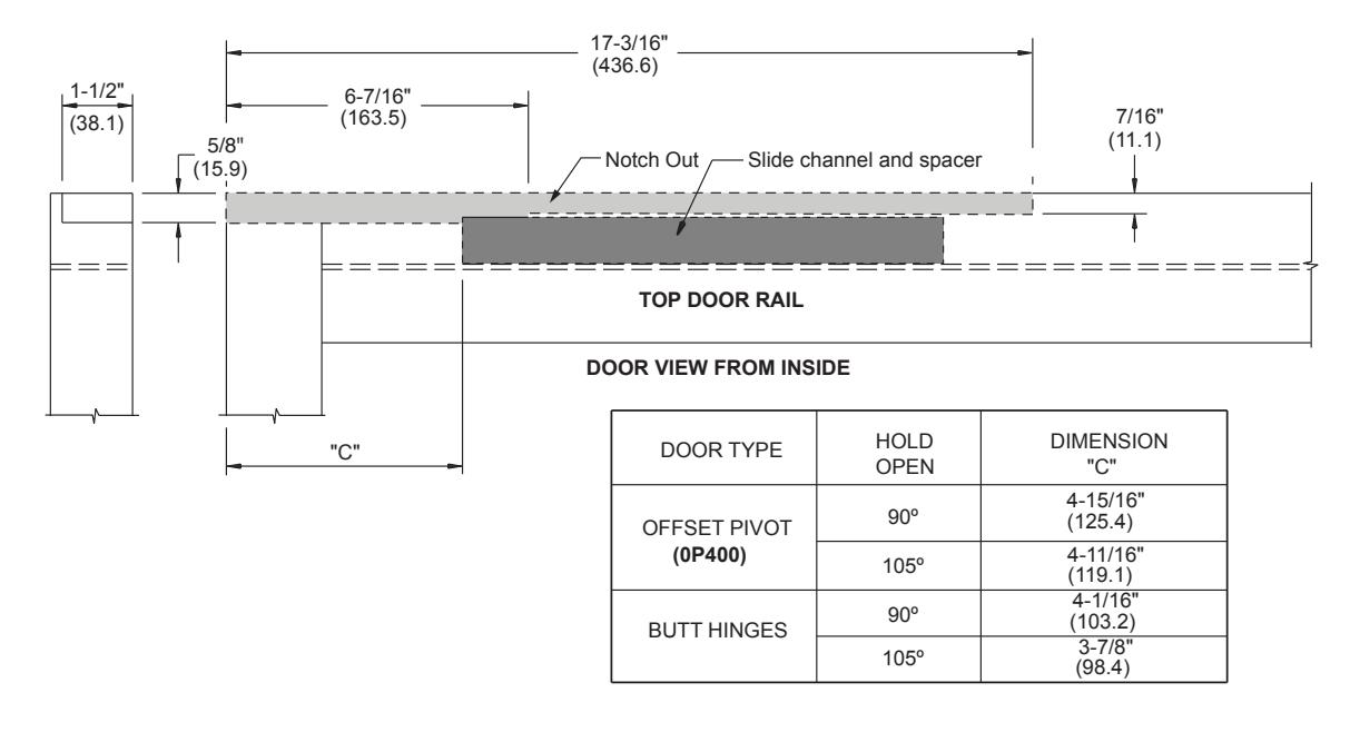
OFFSET ARM COVER CHANNEL RIGHT HAND SHOWN; LEFT HAND OPPOSITE
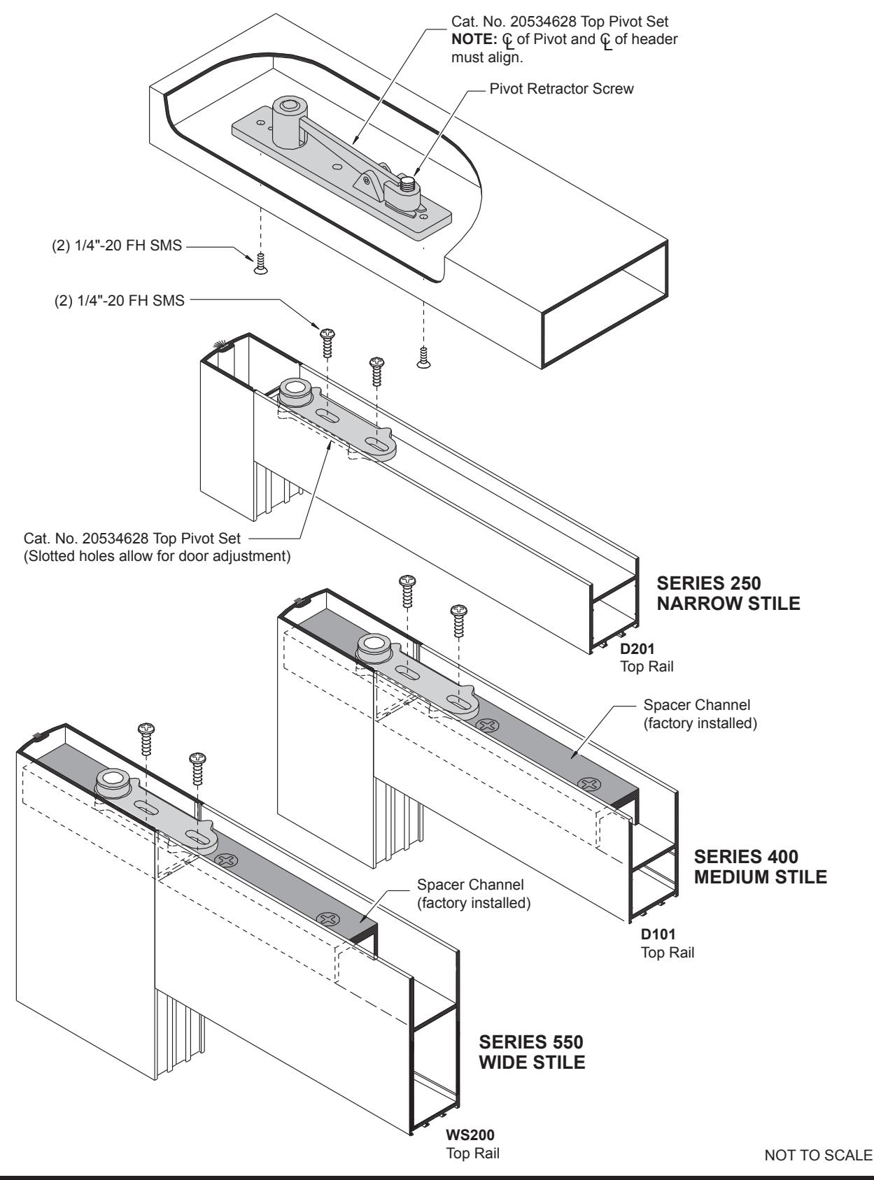
FRAME UNIT FOR CENTER-HUNG DOOR WITH OVERHEAD CONCEALED DOOR CLOSER
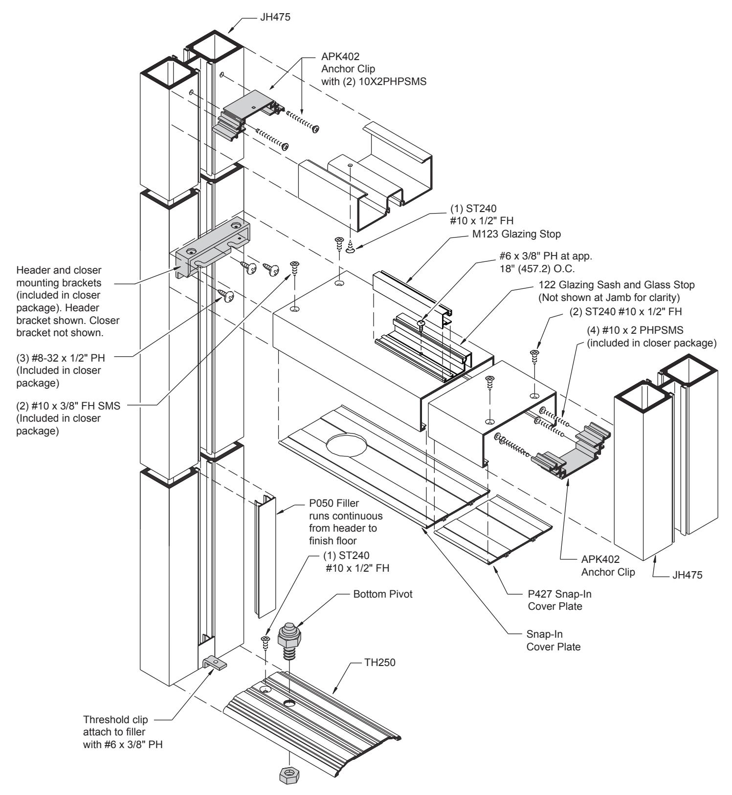
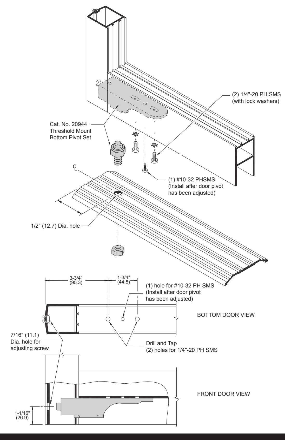
CENTER-HUNG INSTALLATION
DOOR/THRESHOLD PREPARATION
JACKSON OVERHEAD CONCEALED DOOR CLOSER SIDE LOAD CENTER PIVOT DOOR
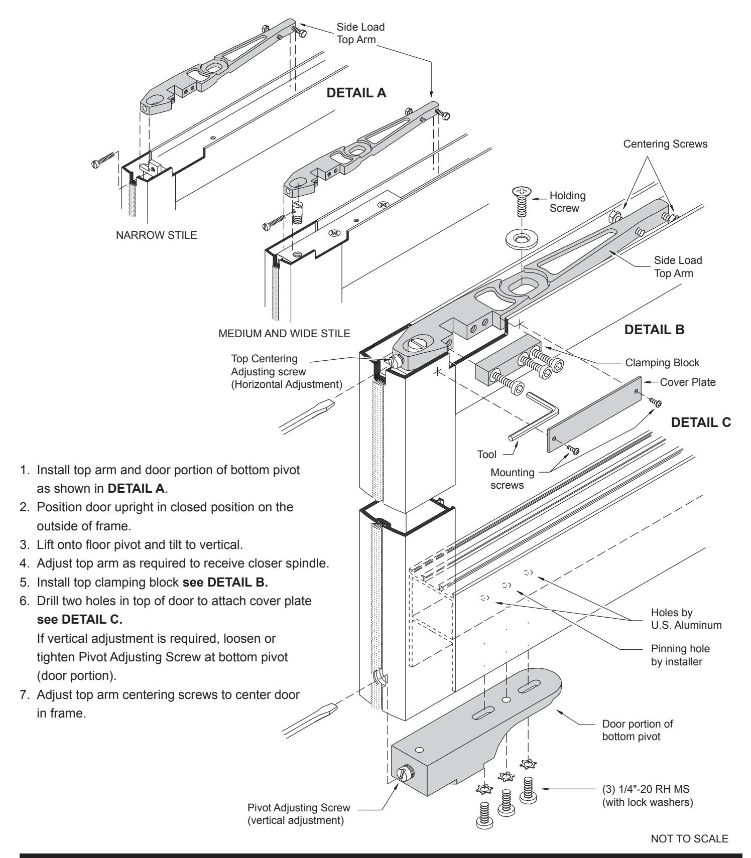
CENTER-HUNG DOOR INSTALLATION WITH A SIDE LOAD TOP ARM
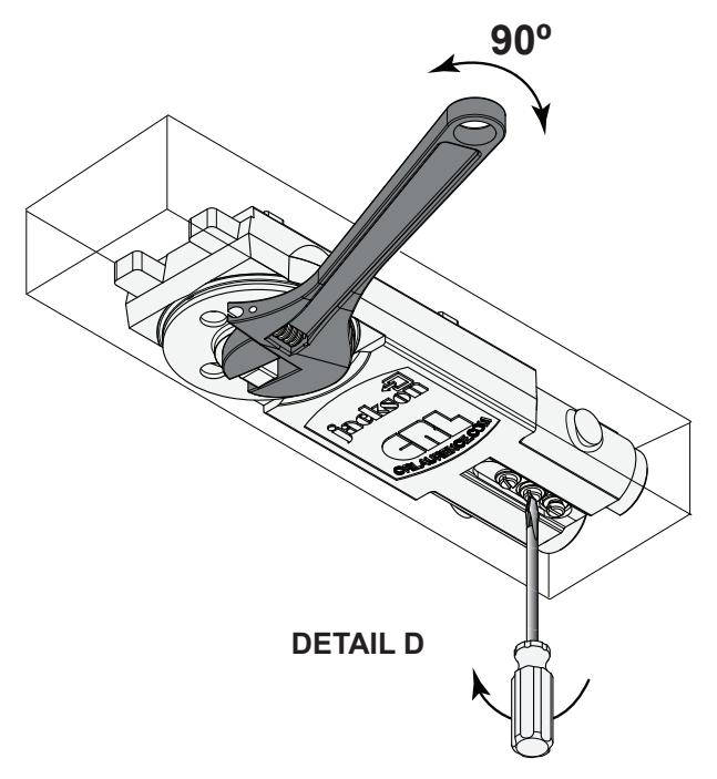
1. Using an open end wrench, turn the spindle of the closer to the hold-open position. Make sure to turn it in the correct direction. If the closer has no hold open feature, turn the spindle with an open end wrench until you get to 90 degrees and then close the "closing-speed adjustment valve" to hold it in place. See DETAIL D .
NOTE: Be careful not to apply excessive torque to the brass "closing-speed adjustment valve" screw, this can cause
damage to the seat.
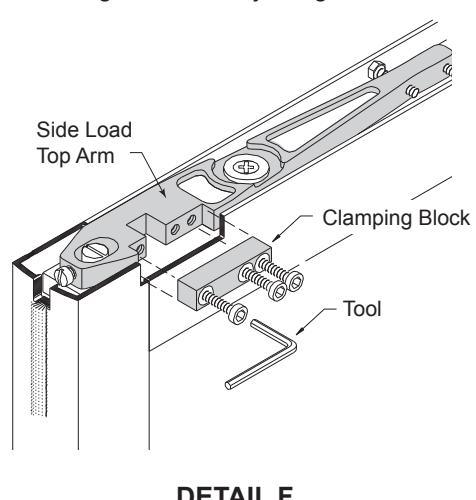
DETAIL E
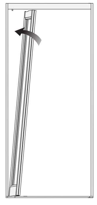
- 2. Tilting the door slightly, lift it into the door frame, perpendicular to the opening, and sit it onto the bottom pivot pin located in the threshold. Make sure that the pivot pin fully engages the pivot socket on the door's bottom rail. Stand the door upright engaging the closer spindle and side slot of the top pivot arm. Hold in place. See DETAIL E .
- 3. Attach the top clamping block with the three 1/4"-20 x 7/8" socket head arm clamping screws and lock washers. DO NOT FULLY TIGHTEN THE CLAMPING SCREWS AT THIS TIME . See DETAIL F .
- 4. Check the top door clearance. If there is more or less than 1/8", you can adjust it by moving the bottom pivot socket up or down using the Pivot Adjusting Screw. See DETAIL G .
CENTER-HUNG DOOR INSTALLATION WITH A SIDE LOAD TOP ARM (CONTINUED)
- 5. After the proper clearances are achieved, proceed to tighten the top pivot arm clamping block to the specifications indicated by the manufacturer.
- 6. Allow the door to close normally by turning the "closing-speed adjustment valve" screw counterclockwise.
- 7. Gently close the door and check alignment.
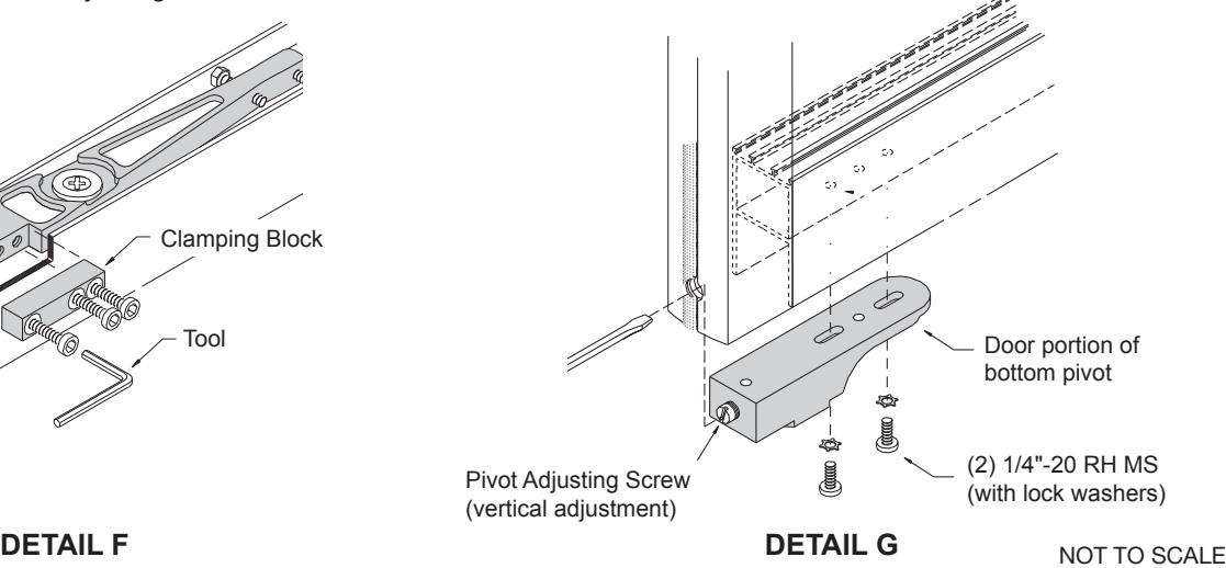
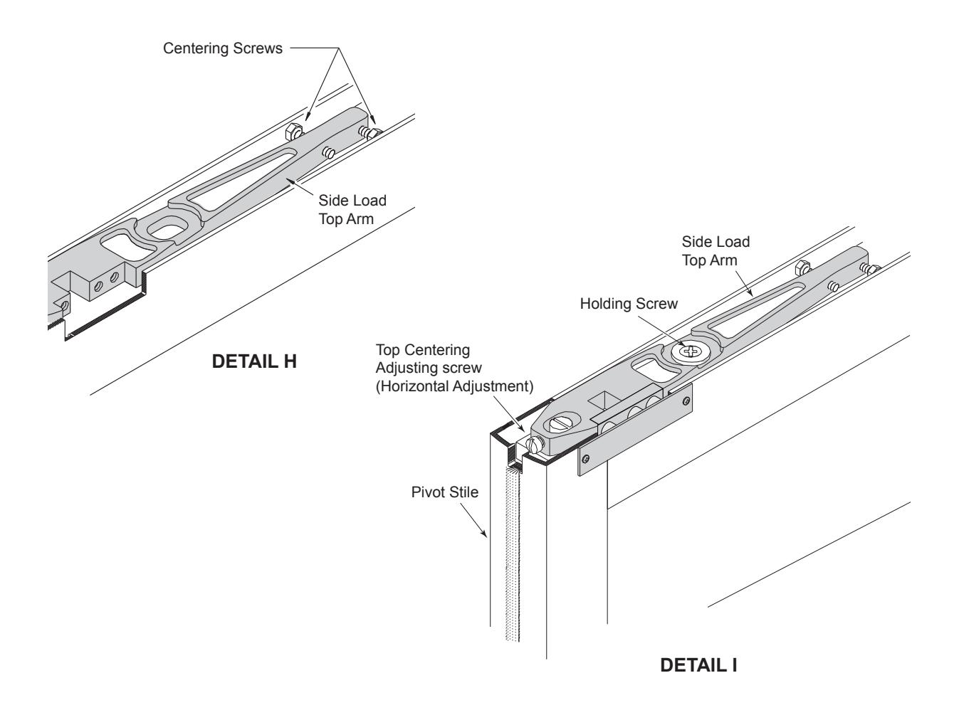
- 8. To center the door in the closed position, adjust the centering screws as shown. See DETAIL H . The door must be open again to 90 degrees to access the centering screws. Each centering screw head must be fully extended to the inside of the top door rail in order to prevent the top arm from spinning. Therefore, as one is tightened, the other must be loosened. NOTE: Over-expanding the centering screws can permanently bulge the top door rail.
- 9. Adjust the door's vertical alignment with the Top Horizontal Adjustment Screw. You must loosen the Holding Screw to do this. When door is correctly positioned, tighten the Holding Screw down firmly. See DETAIL I .
JACKSON OVERHEAD CONCEALED DOOR CLOSER END LOAD CENTER PIVOT DOOR
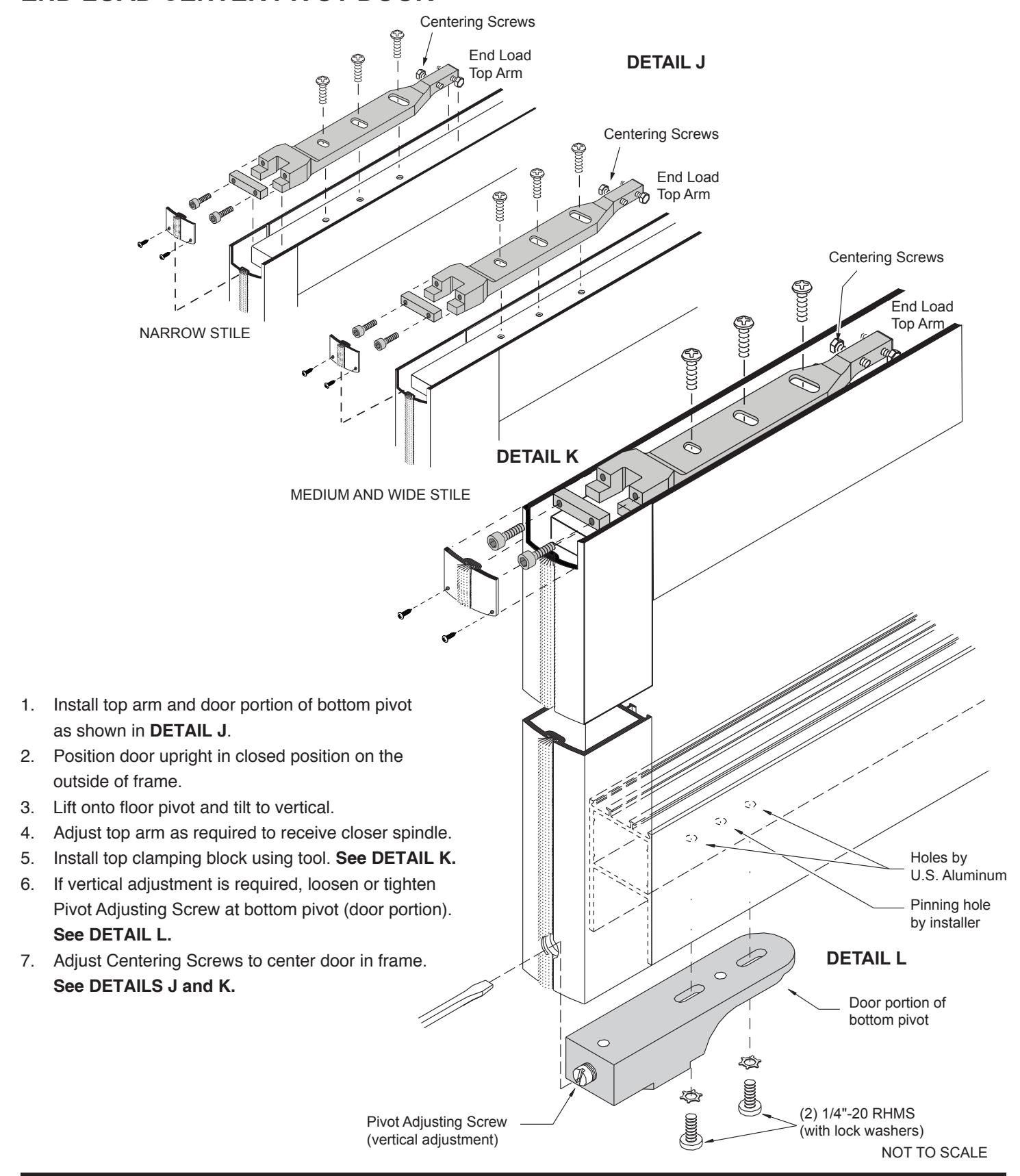
CENTER-HUNG INSTALLATION
TOP ARM ASSEMBLIES
| CENTER-HUNG DOOR CLOSER TOP ARM ASSEMBLIES | |||
|---|---|---|---|
| CAT. NO. | DESCRIPTION | RAIL TYPE | |
| 20400B | CRL Jackson Type "S" Side Load Center-Hung | 1/2" (13 mm) Deep Top Rail | |
| 202000 | CRL Jackson Type "A" End Load Center-Hung | 1" (25 mm) Deep Top Rail | |
| 202010 | CRL Jackson Type "PT" End Load Center-Hung | 7/8" (22 mm) Deep Top Rail | |
| 202085 | CRL Jackson Type "K" End Load Center-Hung | 5/8" (16 mm) Deep Top Rail | |
| CRL8010AS | CRL Jackson Short End Load Center-Hung | For use with CRL Wedge Lock Door Rails | |
| 20510 | CRL Jackson Wood Door Side Load Center-Hung |
5/8" (16 mm) Depth Mortised Rail
(Mortised Channel Included) |
|
| 202090 | CRL Jackson Wood Door End Load Center-Hung |
3/4" (19 mm) Depth Mortised Rail
(Mortised Channel Included) |
|
| CLOSER SELECTION CHART | ||||
|---|---|---|---|---|
| CLOSER | MAXIMUM INTERIOR DOOR | MAXIMUM EXTERIOR DOOR | ||
| Adjustable Spring | 3'-6" (1067) | 3'-0" (914) | ||
| Light Duty Spring | 3'-6" (1067) | 3'-0" (914) | ||
| Regular Duty Spring | 3'-6" (1067) | 3'-0" (914) | ||
| Heavy-Duty Spring | 4'-0" (1219) | 3'-6" (1067) | ||
|
SPRING POWER
ADJUSTMENT DATA |
|---|
|
Closer leaves factory set at size LD
for a 3'-0" (914 mm) door. |
|
To change opening force 1 size
takes approximately 4 turns |
| – Clockwise to increase |
– Counter-Clockwise to decrease
| APPROXIMATE OPENING FORCE IN POUNDS | ||||||||
|---|---|---|---|---|---|---|---|---|
| CLOSER | CENTER HUNG | OFFSET SLIDE-ARM * | ||||||
| 2/6 x 7/0 | 3/0 x 7/0 | 3/6 x 7/0 | 4/0 x 7/0 | 2/6 x 7/0 | 3/0 x 7/0 | 3/6 x 7/0 | 4/0 x 7/0 | |
| Adjustable Spring | N/A | N/A | ||||||
| Light Duty Spring | 10 | 8 | 6 | 5 | 14 | 12 | 10 | 8 |
| Regular Duty Spring | 12 | 10 | 8 | 6 | 17 | 14.5 | 13 | 11 |
| Heavy-Duty Spring | 17 | 15 | 13 | 11 | N/A | 19 | 17 | 15 |
= Adjustable opening force 5 lbs. to 8 lbs. for barrier-free applications for door width noted.* N/A = Application not recommended.
NOTE: Readings are in pound force required to open door and are taken at the lock stile to full degree of opening.
* IMPORTANT: The use of an Offset Slide-Arm will add 2 to 4 pounds of opening force due to track friction and therefore may not allow A.D.A. required opening forces and still provide adequate spring power to control and close the door.
* WARNING: Although A.D.A. Series Closers comply with A.D.A. specified opening forces, they might not provide adequate spring power to control and close the door due to varying site conditions and door sizes.
OVERHEAD CONCEALED DOOR CLOSERS CENTER-HUNG INSTALLATION
|
BLUE
CRL JACKSON ADJUSTABLE SPRING POWER OVERHEAD CONCEALED DOOR CLOSERS |
||||
|---|---|---|---|---|
|
1/2" STANDARD SPINDLE
CAT. NO. |
7/8" EXTENDED SPINDLE
CAT. NO. |
SPRING TYPE | DESCRIPTION | |
| 20101M17 | 20104M17 | Adjustable | 105º No Hold-Open | |
| 20101M18 | 20104M18 | Adjustable | 105º Hold-Open | |
| 20101M19 | 20104M19 | Adjustable | 90º No Hold-Open | |
| 20101M20 | 20104M20 | Adjustable | 90º Hold-Open | |
| BROWN | CRL JACKSON STANDARD OVERHEAD CONCEALED DOOR CLOSERS | |||
|---|---|---|---|---|
|
1/2" STANDARD SPINDLE
CAT. NO. |
7/8" EXTENDED SPINDLE
CAT. NO. |
SPRING TYPE | DESCRIPTION | |
| 20101M01 | 20104M01 | Regular | 105º No Hold-Open | |
| 20101M02 | 20104M02 | Regular | 105º Hold-Open | |
| 20101M03 | 20104M03 | Regular | 90º No Hold-Open | |
| 20101M04 | 20104M04 | Regular | 90º Hold-Open | |
| 20101M09 | 20104M09 | Heavy | 105º No Hold-Open | |
| 20101M10 | 20104M10 | Heavy | 105º Hold-Open | |
| 20101M11 | 20104M11 | Heavy | 90º No Hold-Open | |
| 20101M12 | 20104M12 | Heavy | 90º Hold-Open | |
| BLACK | CRL JACKSON GRADE 1 OVERHEAD CONCEALED DOOR CLOSERS | |||
|---|---|---|---|---|
|
1/2" STANDARD SPINDLE
CAT. NO. |
7/8" EXTENDED SPINDLE
CAT. NO. |
SPRING TYPE | DESCRIPTION | |
| 20111M01B | 20114M01B | Regular | 105º No Hold-Open | |
| 20111M02B | 20114M02B | Regular | 105º Hold-Open | |
| 20111M03B | 20114M03B | Regular | 90º No Hold-Open | |
| 20111M04B | 20114M04B | Regular | 90º Hold-Open | |
| 20111M09B | 20114M09B | Heavy | 105º No Hold-Open | |
| 20111M10B | 20114M10B | Heavy | 105º Hold-Open | |
| 20111M11B | 20114M11B | Heavy | 90º No Hold-Open | |
| 20111M12B | 20114M12B | Heavy | 90º Hold-Open | |
CENTER-HUNG INSTALLATION
PIVOTS
| PIVOT MOUNTS | ||||
|---|---|---|---|---|
| CAT. NO. | DESCRIPTION | APPLICATION | RAIL TYPE | HEIGHT ADJUSTMENT |
| 20902 | CRL Jackson Type "G" |
Floor Mount
Pivot Set |
1-1/2" (38 mm)
Deep Bottom Rail |
3/16" (5 mm) |
| 20944 | CRL Jackson Type "GE" |
Threshold Mount
Pivot Set |
1-1/2" (38 mm)
Deep Bottom Rail |
3/16" (5 mm) |
| 201155 | CRL Jackson Type "BE" |
Threshold Mount
Pivot Set |
1" (25 mm)
Deep Bottom Rail |
N/A |
| Recommended Maximum Weight Capacity for Above Pivots: 125 pounds (56.7 kg) | ||||
| 201570 | CRL Jackson Type "GW" |
Floor Mount
Pivot Set |
1" (25 mm)
Deep Bottom Rail |
N/A |
| 201060 | CRL Jackson Type "P" |
Floor Mount
Pivot Set |
1-9/16" (40 mm)
Deep Bottom Rail |
N/A |
| 20728 | CRL Jackson Type "AE" |
Threshold Mount
Pivot Set |
1" (25 mm)
Deep Bottom Rail |
N/A |
| 201410 | CRL Jackson Type "EF" |
Threshold Mount
Pivot Set |
1-9/16" (40 mm)
Deep Bottom Rail |
N/A |
| 201680 | CRL Jackson Type "BV" |
Combination Mount
Pivot Set |
1" (25 mm)
Deep Bottom Rail |
N/A |
| 201685 | CRL Jackson Type "UP" |
Combination Mount
Pivot Set |
1-9/16" (40 mm)
Deep Bottom Rail |
N/A |
| Recommended Maximum Weight Capacity for Above Pivots: 175 pounds (79.4 kg) | ||||
JACKSON OVERHEAD CONCEALED DOOR CLOSER FOR BUTT HINGE DOOR
TYPICAL DOORWAY FRAME PREPARATION
JACKSON OVERHEAD CONCEALED DOOR CLOSER FOR OFFSET PIVOT DOOR, 90 DEGREE SWING
HEADER PREPARATION NOTE: For Closer Location
NOT TO SCALE HEADER BOTTOM VIEW
JACKSON OVERHEAD CONCEALED DOOR CLOSER FOR OFFSET PIVOT DOOR, 105 DEGREE SWING
HEADER PREPARATION
NOTE: For Closer Location in Header, See Page 06 .
HEADER BOTTOM VIEW
NOT TO SCALE
OFFSET PIVOT INSTALLATION
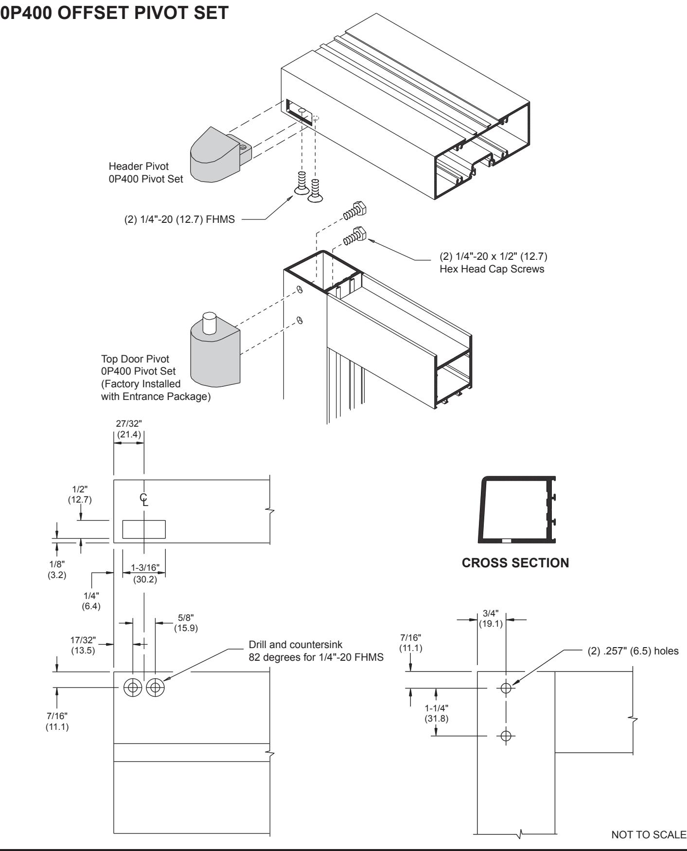
OFFSET PIVOT INSTALLATION
DH022 INTERMEDIATE PIVOTS
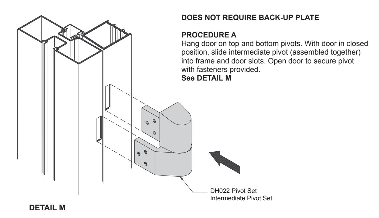
PROCEDURE B
Install pivot leaves on frame and door. Remove cap screw from jamb portion of pivot and lower pin to clear. Hang door on top and bottom pivots. Raise pivot pin as required and replace cap screw.
See DETAIL N
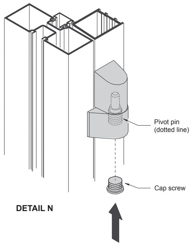
To remove existing doors with intermediate pivots, remove cap screw and lower pivot pin to clear.

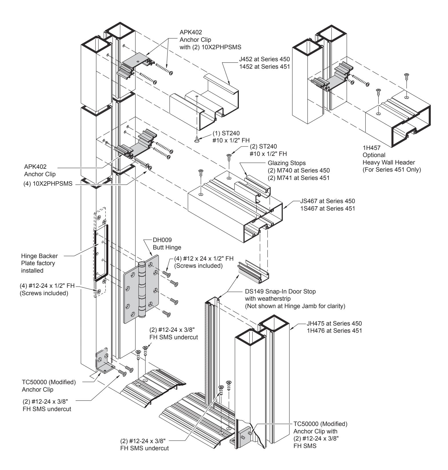
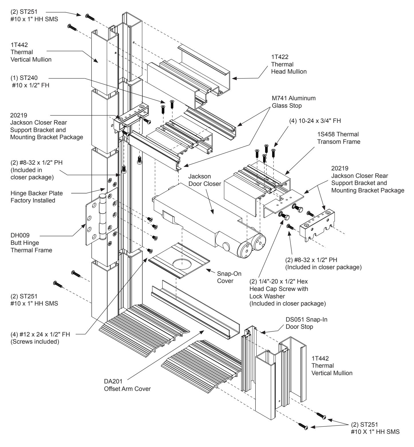
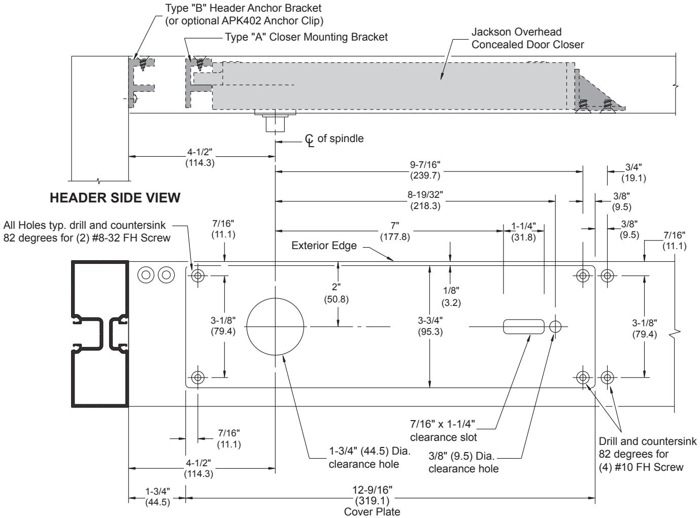
HEADER FOR JACKSON OVERHEAD CONCEALED DOOR CLOSER WITH OFFSET ARM
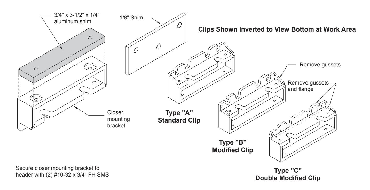
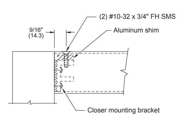
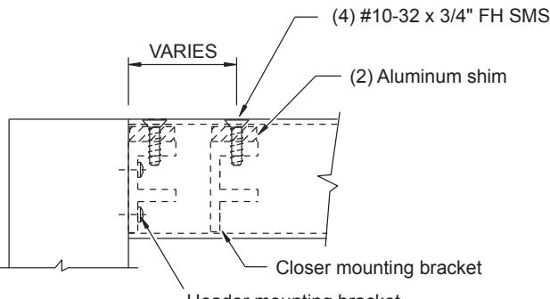
Header mounting bracket Option: APK402 anchor clip may also be used to fasten header to jamb when using a Jackson closer with 105 degree swing HO and offset pivot.
hung door 90 degree swing
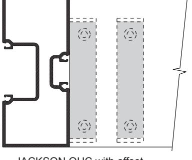
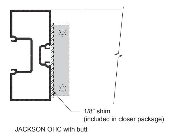
JACKSON OHC with offset pivot door
JACKSON OHC with butt hung door 105 degree swing
NOT TO SCALE
JACKSON OVERHEAD CONCEALED DOOR CLOSER FOR OFFSET PIVOT DOOR
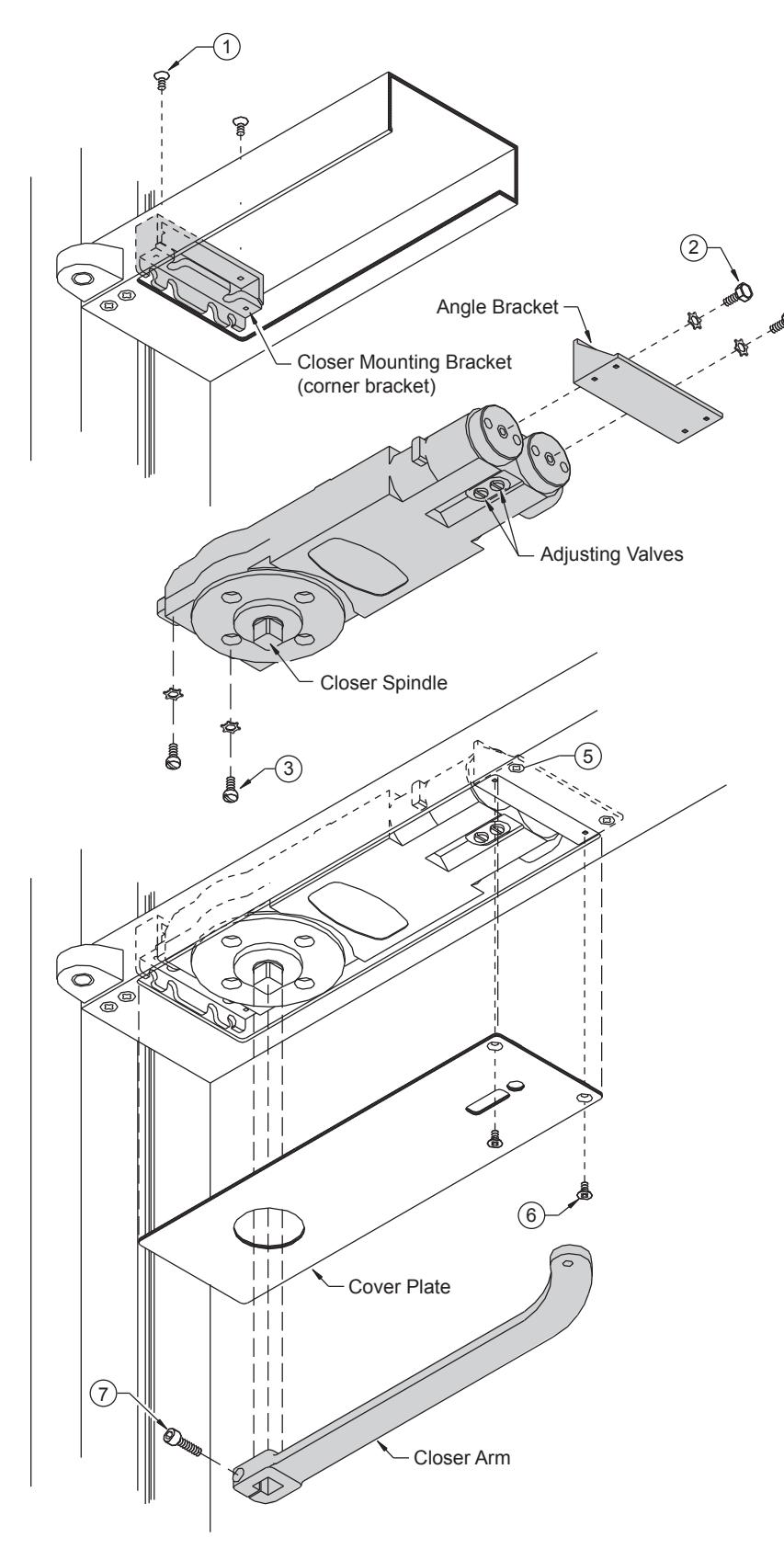
- 1. Mount corner bracket into header with (2) 10-32 x 3/8" FH SMS.
- 2. Mount angle bracket to closer with (2) 1/4"-20 x 1/2" Hex Head Cap Screw and lock washer.
- 3. Install (2) 1/4"-20 x 5/8" Round Head MS with lock washers into lugs of closer. Do not tighten screws.
- 4. Set closer onto header and align angle bracket holes with holes in header. Closer lugs shall rest on corner bracket.
- 5. Fasten angle bracket to header with (2) 10-24 x 3/8" FH SMS. Tighten Round Head Screws.
- 6. Install cover plate and secure to angle with (2) 10-24 x 3/8" FH SMS.
- 7. Mount arm on spindle and secure with 1/4"-20 x 7/8" Socket Head Cap Screw.
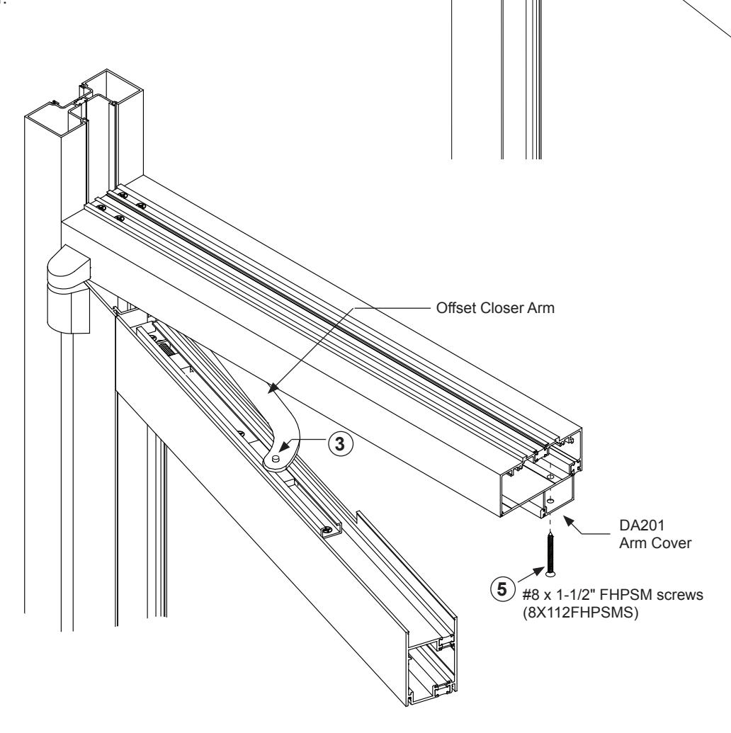
OFFSET CLOSER ARM INSTALLATION
JACKSON OVERHEAD DOOR CLOSER WITH TOP AND BOTTOM OFFSET PIVOTS
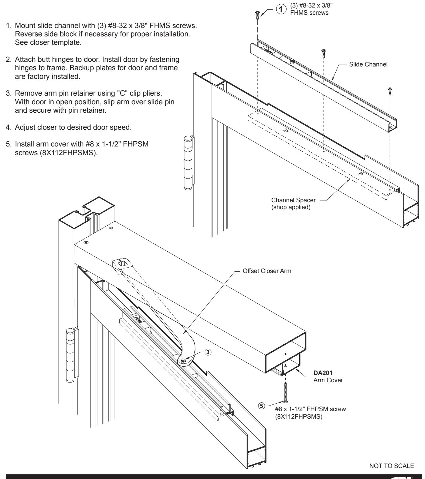
- 1. Mount slide channel with (3) #8-32 x 3/8" FHMS screws. Reverse slide block if necessary for proper installation. See closer template.
- 2. Set door onto bottom pivot at an angle. Tilt to vertical holding top pivot pin down until it aligns with header pivot portion. Release pin.
- 3. Before positioning the offset closer arm in the top rail remove the arm pin retainer with "C" clip pliers, swing door in the open position and slip arm over slide pin and secure with pin retainer.
- 4. Adjust closer to desired door speed.
- 5. Install arm cover with #8 x 1-1/2" FHPSM screws (8X112FHPSMS).
- 6. Glaze door.
NOT TO SCALE
Slide Channel
Slide Block
(3) #8-32 x 3/8" FHMS screws
1

OFFSET CLOSER ARM INSTALLATION
INSTALL JACKSON OVERHEAD DOOR CLOSER BUTT HINGE DOOR WITH 90 DEGREE
OFFSET ARM/CHANNEL ASSEMBLIES
| OFFSET ARM AND SLIDE CHANNEL ASSEMBLIES | ||||
|---|---|---|---|---|
| CAT. NO. | DESCRIPTION | OVERALL LENGTH | ARM FINISH | |
| 20900LC628 | CRL Jackson Deep Mortised Type | 14" (356 mm) | Aluminum | |
| 20900LC313 | CRL Jackson Deep Mortised Type | 14" (356 mm) | Dark Bronze | |
| 201134LC628 | CRL Jackson Shallow Depth Mortised Type | 12-7/8" (327 mm) | Aluminum | |
| 201134LC313 | CRL Jackson Shallow Depth Mortised Type | 12-7/8" (327 mm) | Dark Bronze | |
| 201312LC628 |
CRL Jackson Shallow Depth Mortised Type
With Enhanced Pre-Load |
12-7/8" (327 mm) | Aluminum | |
| 201312LC313 |
CRL Jackson Shallow Depth Mortised Type
With Enhanced Pre-Load |
12-7/8" (327 mm) | Dark Bronze | |
| OFFSET ARM ASSEMBLY COVERS | |||
|---|---|---|---|
| CAT. NO. | HANDING | FINISH | |
| 20106628 | Left Hand | Aluminum | |
| 20106313 | Left Hand | Dark Bronze | |
| 20117628 | Right Hand | Aluminum | |
| 20117313 | Right Hand | Dark Bronze | |
CENTER PIVOT - TOP PORTION FOR FLOOR MOUNTED CLOSER
FRAME UNIT FOR BUTT HUNG DOOR WITH SURFACE MOUNTED CLOSER