Jackson 900 Floor Mounted Door Closer Center Hung and Offset Installation Instructions – English
Open the original PDF document
View PDFINSTALLATION INSTRUCTIONS
CRL JACKSON 900 SERIES FLOOR MOUNTED DOOR CLOSERS CENTER HUNG AND OFFSET

Phone: (800) 421-6144 • Fax: (800) 262-3299 crlaurence.com • usalum.com • crl-arch.com
INTRODUCTION
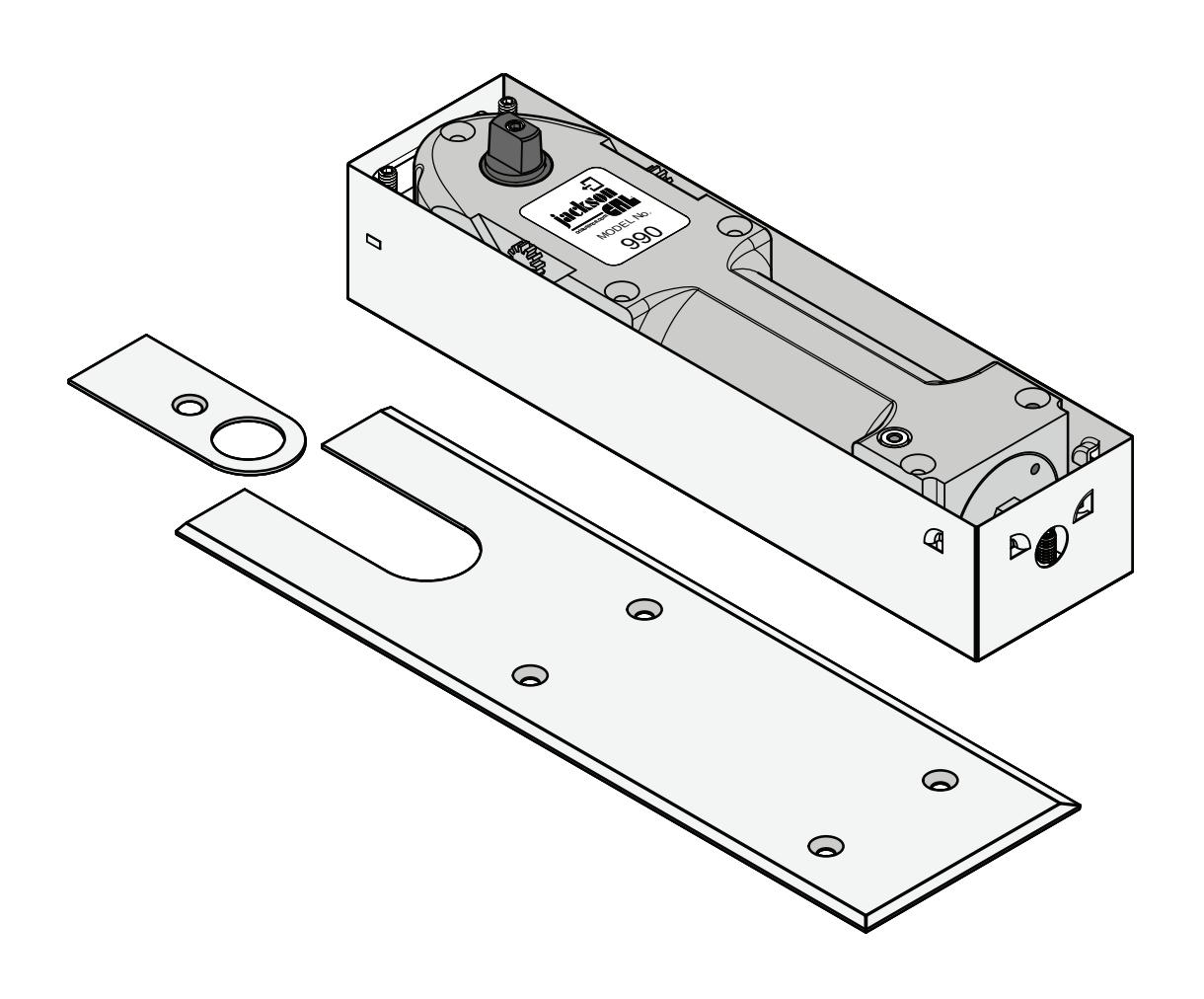
The CRL Jackson® 900 Series consist of a comprehensive range of closer units and accessories. Designed for use with larger and heavier interior or exterior doors weighing up to 1,000 lbs. (453 kg). Center-Hung and Offset accessories available include a full range of interchangeable extension spindles, center-hung and offset bottom arms, top pivots, cover plates, and multiple accessories for use with wood, metal or glass doors.
These 180º degree swing, double-acting, non-handed closers are available in dual 90º/120º, 105, or 120º degree hold-open and no hold-open models. They feature a multi-size spring power adjustable range of 1 thru 6 to control a wide range of door weights and sizes.
WARNING: Failure to comply with the installation procedures may void the warranty.
The rapidly changing technology within the architectural aluminum products industry demands that C.R. Laurence/U.S. Aluminum reserve the right to revise, discontinue, or change any product line, specification, or electronic media without prior written notice.
NOTE: Dimensions in parentheses ( ) are millimeters unless otherwise noted.
CENTER HUNG DOORS
1. The standard dimension for a center hung door's pivot point to the jamb is 2-3/4" (69.8). NOTE: When calculating the placement of the closer and it's cement case, keep in mind that the offset center line location of the Spindle attached to the closer has an adjustable range of 1/4" (6.4), from 1-3/4" to 2" (45-51) from edge of the cement case.To avoid interference, always included an 1/8" (3.1) clearance between the door jamb and door edge.
NOTE: Caution must be exercised to avoid interference with the jamb if the door is allowed to swing past 110º degree.
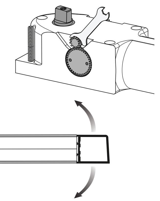
2. Fabricate a recess opening in the floor for the closer and cement case. When completed, set the cement case in the prepared floor opening with the fixed clamp side of the case nearest to the door jamb. (Fig. 4) The closer mechanism can be removed from it's case if needed. Simply turn the set screws on the Fixed and Removable Clamps to release the mechanism. Lift the front of the closer using the adjustment Spanner Wrench. (Fig. 5)
NOTE: If door pivot hardware has been factory installed, proceed to step 4.
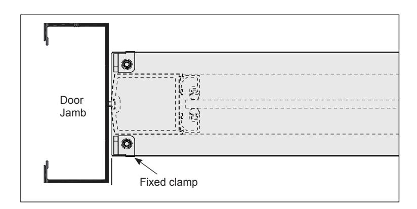
FIG. 4
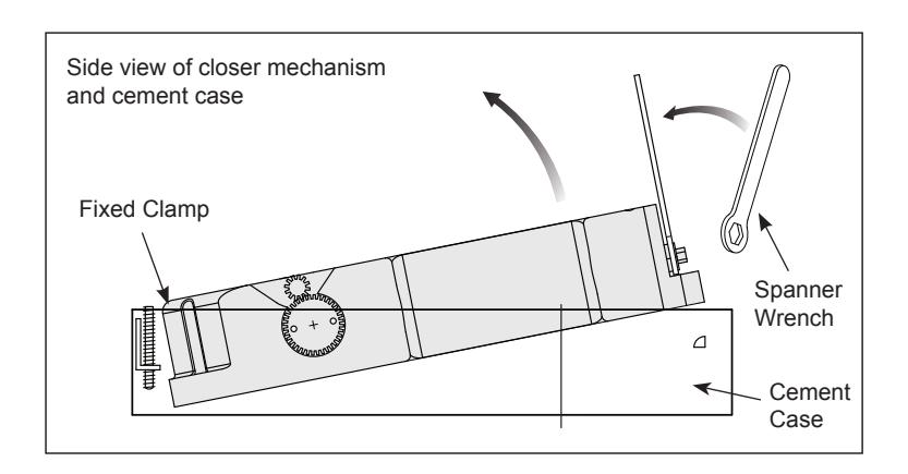
FIG. 5
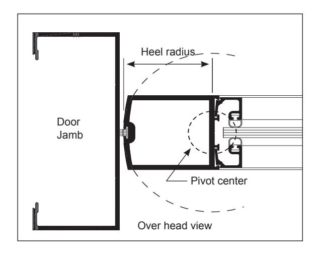
FIG. 1
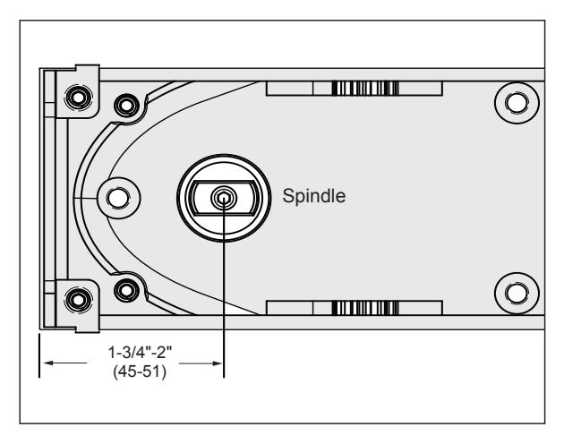
FIG. 2
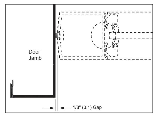
FIG. 3
CENTER HUNG DOORS (CONTINUED)
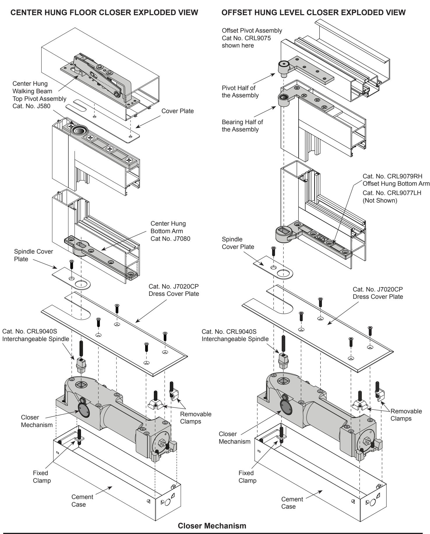
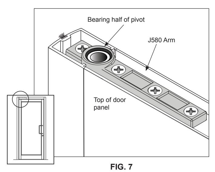
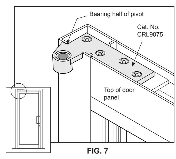
- 3. Install the Pivot Hardware into the door panel and door frame. On the pivot center line, mortise the bottom Pivot Arm into the bottom Door Rail and Hinge Stile. (Fig. 6) Do the same with the top door rail, mortise the Bearing Half of the Top Pivot assembly. (Fig. 7) Notching may be required on aluminum door Hinge Stiles and Rails to accommodate the pivot hardware. At the door frame Header, mortise the Pivot Half or Walking Beam Pivot of the assembly. (Fig. 8)
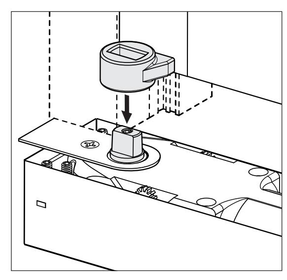
- 4. Replace the closer mechanism if it was removed from the Cement Case. Ensure the removable clamps are engaged in their sockets and loosely tighten the clamp set screws to allow for adjustment. Secure the Spindle Cover with a 12-24 x 1/2" (M6-1.0 x 12 mm) flat head screw. (Fig. 9)
- 5. Position the door over the floor closer and align the Bottom Pivot Arm over the Spindle. Try to keep the door as vertical as possible to avoid excessive torque on the Spindle. (Fig. 9)
- 6. If using a Walking Beam Top Pivot, Cat. No. J580, partially open the door to access the adjustment screws. Follow the instructions included with the Top Pivot. (Fig. 10)
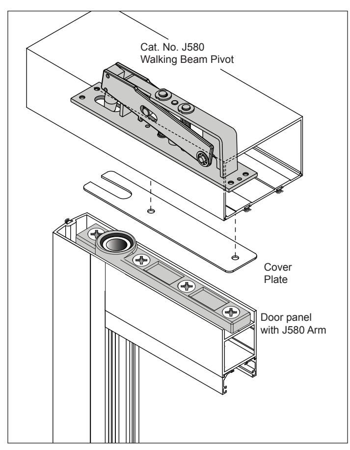

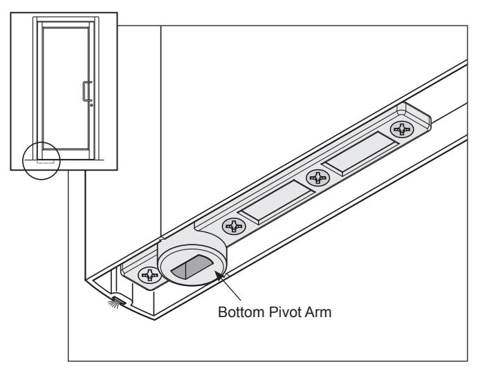
FIG. 6
Bottom Pivot Arm Spindle with cover
FIG. 9
CENTER HUNG DOORS (CONTINUED)
- 7. Adjust the vertical gaps to 1/8" (3.1) between the door panel and the frame using the top pivot lateral adjustment and by sliding the closer mechanism within the Cement Case. Fully tighten the Top Pivot retracting screw until the position indicators are level with the base plate.
- 8. Check that the door returns to the correct center closed position.
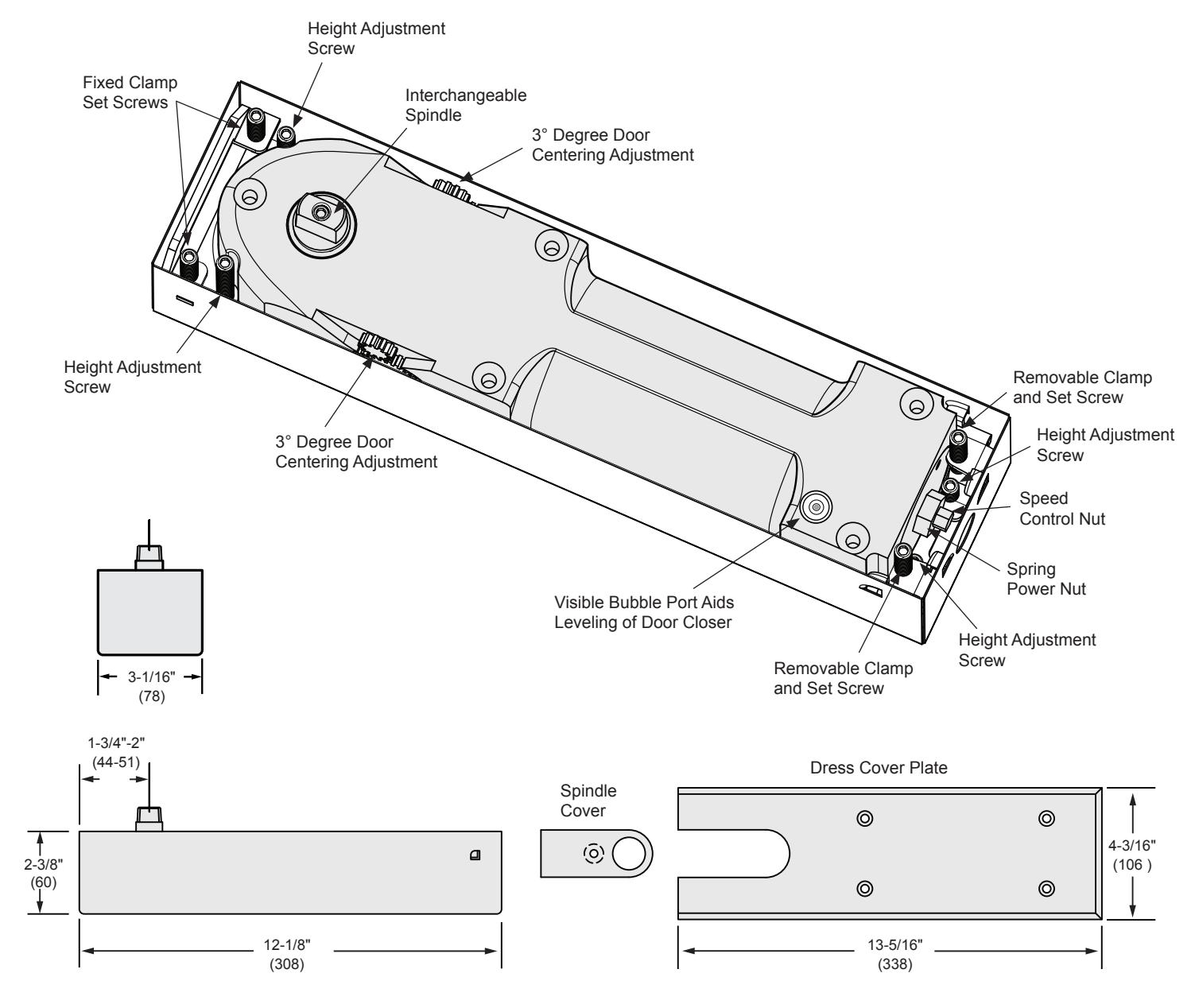
- 9. Adjust the gap at the top of the door to 1/8" (3.1) using the 4 height adjustment screws on the closer. Loosen all four clamp screws to allow the mechanism to rise while adjusting. Use the Bubble Port to make sure that the mechanism is level. Longer Spindle inserts are available from 5/16" to 1-1/2" (7.9 - 38) bottom clearance to accommodate different threshold and finished floor heights.
- 10. Fully tighten each clamp screws and height adjustment screws for a firm fit. (Fig. 11)
- 11. Adjust the center position of the door by using the Centering Adjustment Gears on either side of the closer mechanism. (See Page 10)
- 12. Adjust the smaller hex nut to control a smooth closing speed of approximately 5 to 7 seconds from a 90° degree open position. (Fig. 11)
- 13. The 900 Series Floor Closer features a spring power range of size 1-6. The Chart on the right shows the approximate amount of the full turns required to advance from '0' thought the spring power range up to size '6'. The standard factory setting is at approximately mid-range, size '3', so to increase to size '4' will require three additional full clockwise turns or to decrease to size '2', two full counter-clockwise turns.
- 14. Oversize doors may require an increase in the backcheck resistance. Adjust the larger hex nut clockwise to increase the power of the spring or counter-clockwise to decrease the power.
- 15. Attach the Dress Cover Plate to the closer with the four flat head screws provided when all adjustments are completed.
NOTE: Although the 900 Series Floor Closers feature adjustable spring power that allows these closers to be set to comply with A.D.A. specified opening forces, they may not provide adequate spring force to control and close the door due to minimized closing force, varying site conditions, and door size.
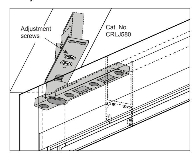
FIG. 10
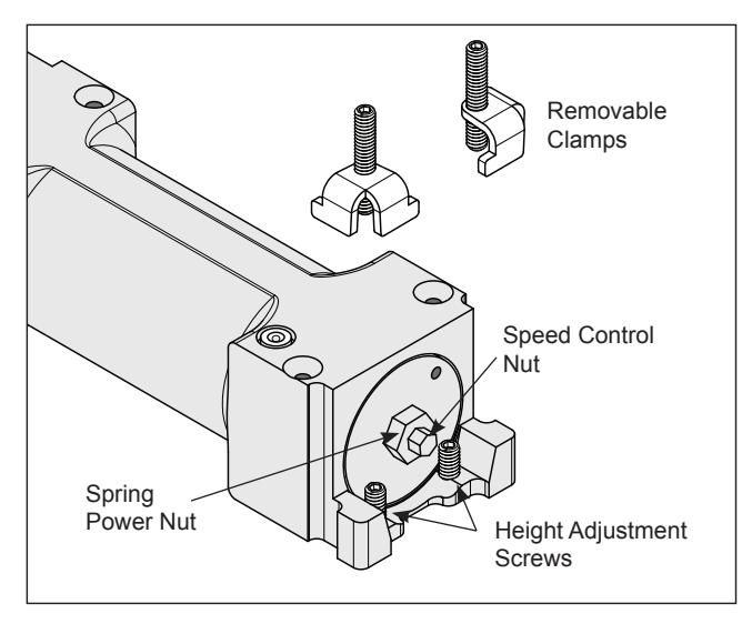
FIG. 11
J900 SERIES FLOOR CLOSER SPRING POWER SETTINGS
| APPROXIMATE TURNS FROM | ||
|---|---|---|
| FACTORY SETTINGS | ZERO POWER | SPRING POWER SIZE |
| -4 | 4 | 1 |
| -2 | 6 | 2 |
| FACTORY SETTING | 8 | 3 |
| +3 | 11 | 4 |
| +8 | 16 | 5 |
| +15 | 23 | 6 |
OFFSET HUNG DOORS
1. Determine the pivot center of the Offset Arm at the bottom of the door to be installed. The pivots center can be offset by 3/4" (19) or 1-1/2" (38). The offset is measured from the face of the door to the pivot center. (Fig. 1)
NOTE: When calculating the placement of the closer and it's cement case, keep in mind that the offset center-line location of the Spindle attached to the closer has an adjustable range of 1/4" (6.4), from 1-3/4" to 2" (45-51) from edge of the cement case. (Fig. 2)
To avoid interference, always included an 1/8" (3.1) clearance between the door jamb and door edge. (Fig. 3)
2. Fabricate a recess opening in the floor for the closer and cement case. When completed, set the cement case in the prepared floor opening with the fixed clamp side of the case nearest to the door jamb. (Fig. 4) The closer mechanism can be removed from it's case if needed. Simply turn the set screws on the Fixed and Removable Clamps to release the mechanism. Lift the front of the closer using the adjustment Spanner Wrench included in the kit. (Fig. 5)
NOTE: Intermediate Pivots, such as Cat. No. M19, should be used to maintain door alignment and/or to help support the door weight. One Pivot is recommended for a door up to 7' 6" (2286) tall and one additional Pivot for each additional 30" (762) or fraction there of.
NOTE: If the Pivot Hardware has been factory installed, proceed to step 4.
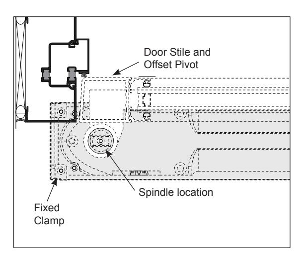
FIG. 4
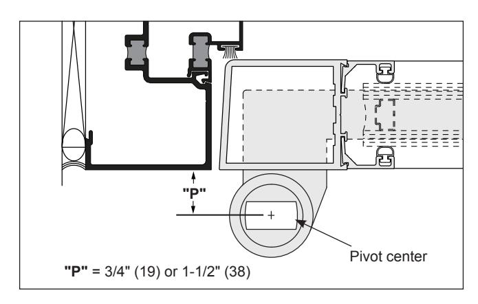
FIG. 1
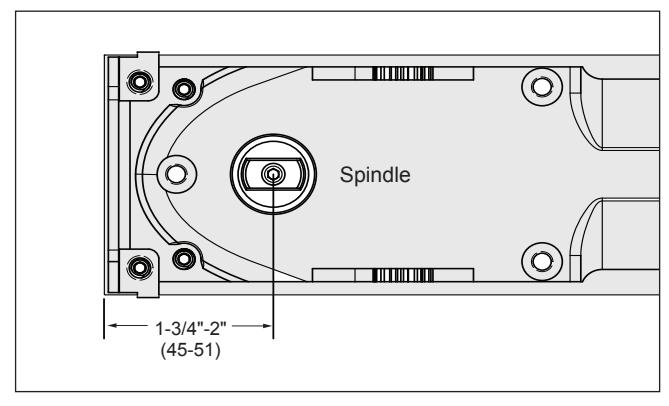
FIG. 2
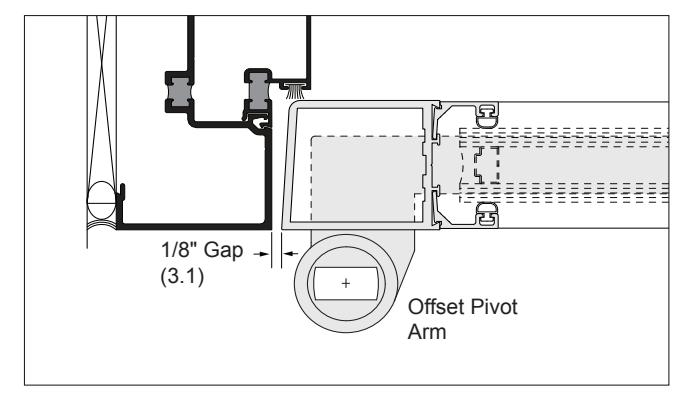
FIG. 3
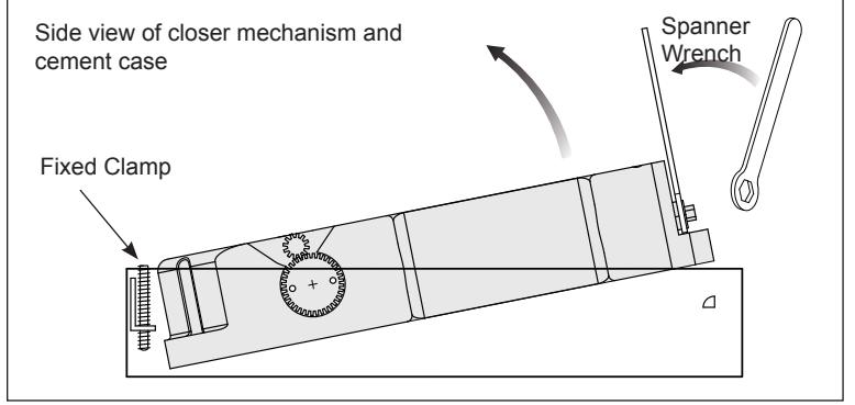
FIG. 5
OFFSET HUNG DOORS (CONTINUED)
- 3. Install the Offset Pivot Hardware into the door panel and door frame. Mortise the bottom Offset Pivot Arm into the Bottom Door Rail while keeping in mind the pivot center of the arm and it's alignment with the Spindle on the closer. (See Fig. 6 and 9) Do the same with the top door rail, mortise the bearing half of the Offset Pivot assembly. (Fig. 7) On aluminum doors, notching the Hinge Stile and Rails may be necessary to accommodate the pivot arms. Also, a spacer bar may have to be installed to build out the pivots. At the door frame Header, mortise the Pivot Half of the Offset Pivot assembly. Remove the Pivot Pin from the hinge body prior to installing the door. (Fig. 8)
- 4. Replace the closer mechanism if it was removed from the Cement Case. Ensure the removable clamps are engaged in their sockets and loosely tighten the clamp set screws to allow for adjustment. Secure the Spindle Cover with a 12-24 x 1/2" (M6-1.0 x 12 mm) flat head screw. (Fig. 9)
- 5. Position the door over the floor closer and align the Bottom Pivot Arm over the Spindle. Try to keep the door as vertical as possible to avoid excessive torque on the Spindle. (Fig. 9)
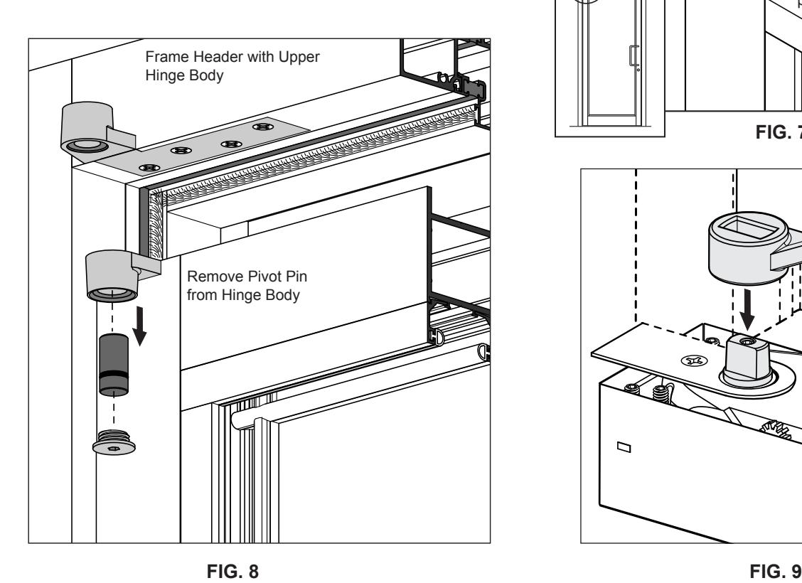
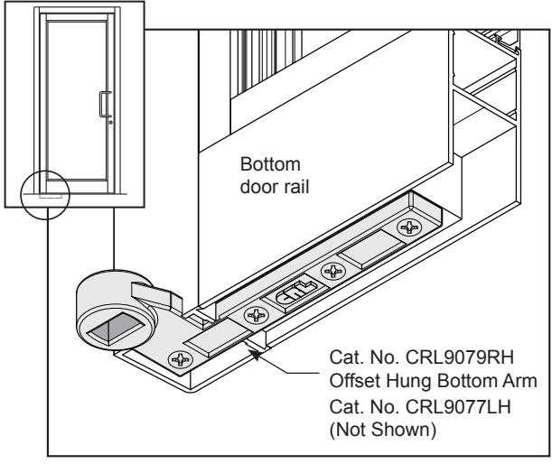
FIG. 6
OFFSET HUNG DOORS (CONTINUED)
- 6. Tilt door panel into the frame and align the pivot halves together. Join the hinge with the Pivot Pin followed by the Dust Cover. (Fig. 10)
- 7. Adjust the vertical gaps to 1/8" (3.1) between the door panel and the frame by sliding the closer mechanism within the Cement Case. (Fig. 11)
- 8. Adjust the gap at the top of the door to 1/8" (3.1) using the four Height Adjustment Screws. (Page 02) Loosen the Clamp Screws to allow the mechanism to rise while adjusting. Use the Bubble Port to make sure that the mechanism is level. Longer Spindle Inserts are available from 5/16" - 1-1/2" (8 - 38) bottom clearance to accommodate different threshold and finished floor heights.
- 9. After adjustments, fully tighten each screw. On the Offset Pivot Hardware, it may be difficult to gain access to all four screws due to the location under the Hinge Jamb. So plan ahead.
- 10. Adjust the closing speed by turning the smaller hex nut at the end of the mechanism. A smooth closing speed of approximately 5 to 7 seconds from a 90° degree open position is good. (See Page 6, Fig. 11)
- 11. The 900 Series Floor Closer features a spring power range of size 1-6. The standard factory setting is at approximately mid-range, size '3'. The chart on Page 6 shows the approximate amount of full clockwise or counter-clockwise turns required to increase or decrease from one size to the next.
NOTE: Although the 900 Series Floor Closers feature adjustable spring power that allows these closers to be set to comply with A.D.A. specified opening forces, they may not provide adequate spring force to control and close the door due to minimized closing force, varying site conditions, and door size.
- 12. Oversize doors may require an increase in the backcheck resistance. Adjust the larger hex nut clockwise to increase the power of the spring or counter-clockwise to decrease the power.
- 13. When all adjustments are completed, attach the Dress Cover Plate to the closer mechanism with (4) 1/2" flat head screws.
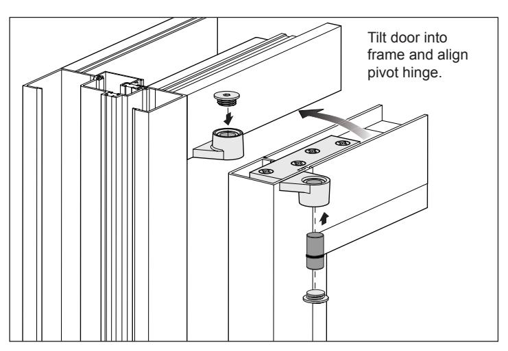
FIG. 10
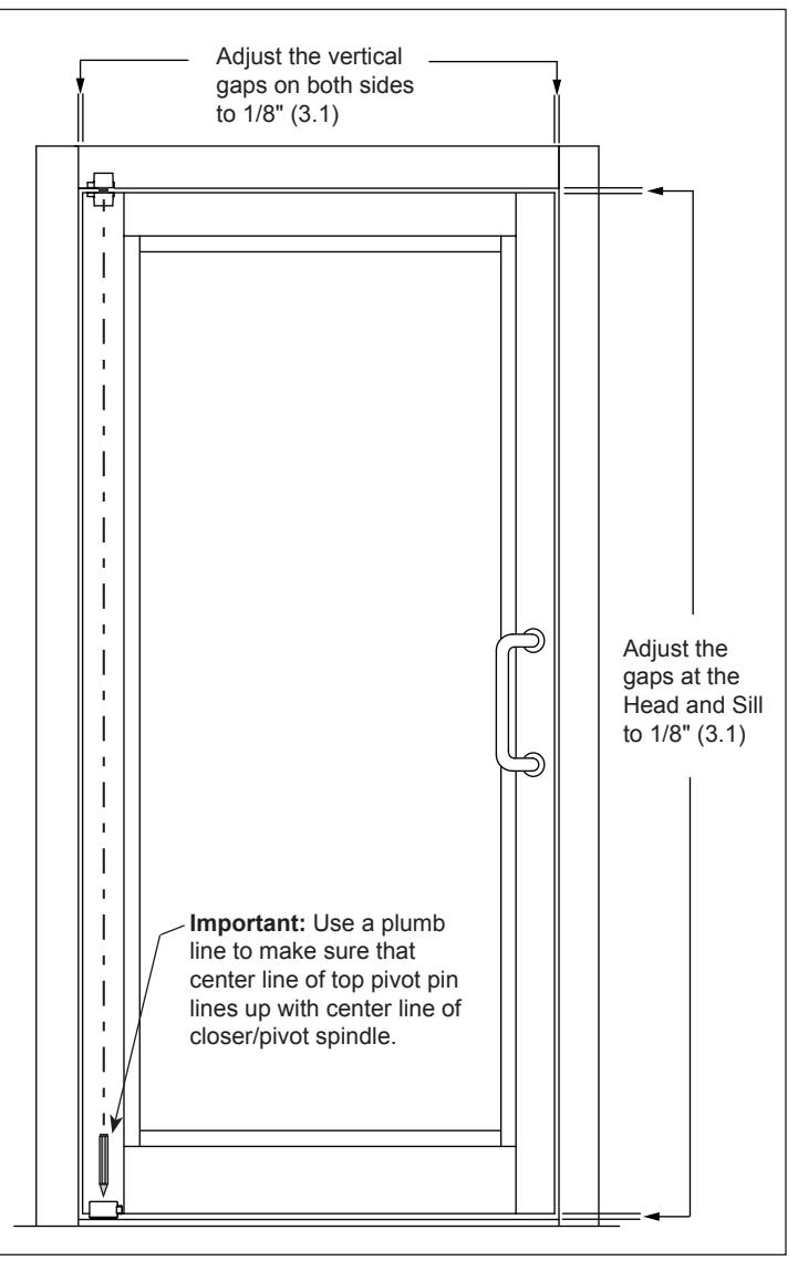
FIG. 11
CENTERING THE DOOR
The 900 Series Floor Closer is equipped with Centering Gears on both sides of it's housing. An adjustment wrench is provided with the kit. Remove the Dress Cover to expose the mechanism. With the wrench, try 1/4 turn and check door by opening all of the way and letting it self close. Adjust until door centers in the opening. Maximum adjustment is 3º degrees in and out. Do not force the gear beyond that. If door will still not center, adjust the position of the closer body inside the cement case and make certain that all fasteners and brackets are securely fastened in place.
Offset Pivot Condition
MAINTENANCE
The internal mechanism of the floor closer is immersed in oil and has been designed so that it requires no maintenance. It is protected from misuse by an overload safety feature. Once the floor closer has been installed and adjusted to suit local conditions an annual check is recommended to ensure that:
The door closes freely and positively into its frame from any angle without slamming. All fasteners to the unit and accessories are tight.
If the door does not fully close, it may indicate that the power of the floor closer requires some adjustment. Any excessive force to close the door may indicate that the door is distorted or misaligned.
WEATHER CONDITIONS
Due to severe temperature changes from Winter to Summer, the closing speed may need to be adjusted periodically to maintain a smooth closing cycle.
EXCESSIVE MOISTURE
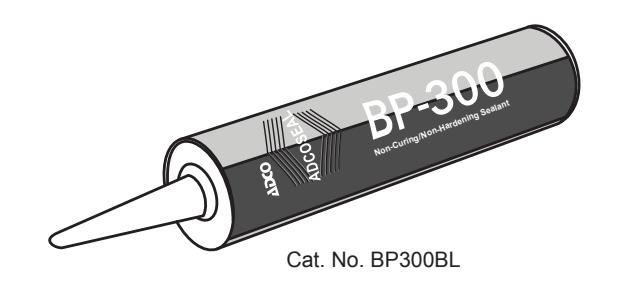
If site conditions will subject the closer to excessive moisture or a corrosive environment, it is recommended that the closer be protected by using a sealant such as, Cat. No. BP300BL, which is a permanently pliable formula that will not harden and has an excellent resistance to adverse weather conditions.
WARNING:
Never Attempt to disassemble a Jackson 900 Series floor closer. Serious injury can occur.