Jackson 896 Removable Mullion Installation Instructions
Open the original PDF document
View PDFINSTALLATION INSTRUCTIONS
CRL JACKSON 896
REMOVABLE MULLION

Phone: (800) 421-6144 • Fax: (866) 921-0531 crlaurence.com • usalum.com • crl-arch.com
ORDER OF ASSEMBLY AND INSTALLATION
| ORDER OF ASSEMBLY AND INSTALLATION | 02 |
|---|---|
| COMPONENTS | 03-04 |
| BOTTOM MOUNTING MULLION SHOE INSTALLATION | 05 |
| TOP MOUNTING MULLION SHOE INSTALLATION | 06 |
| MULLION INSTALLATION | 07 |
| MULLION STABILIZERS INSTALLATION | 08 |

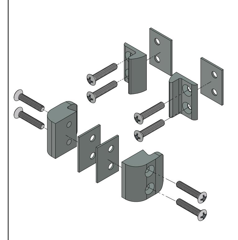
COMPONENT PARTS
No. 30-2497 for 1295 Panic Device No. 30-2530 for 2095 Panic Device
No. 30-784 for 1095 Panic Device
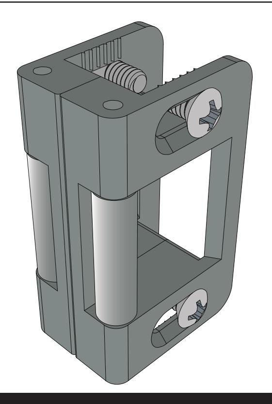
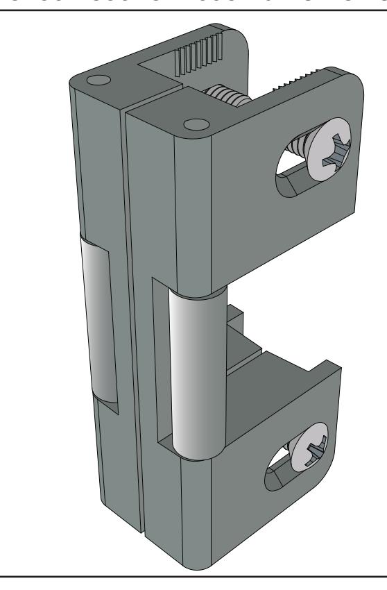
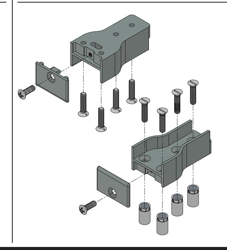
No. 30-702 Top and Bottom Shoes
COMPONENT PARTS
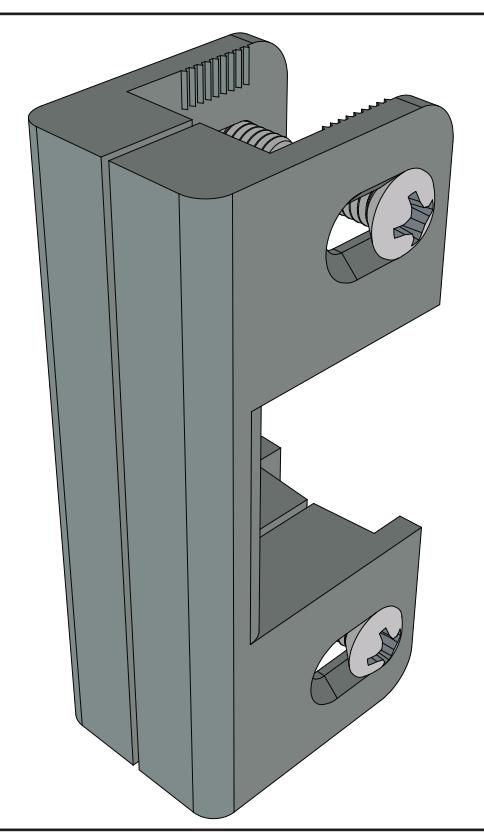
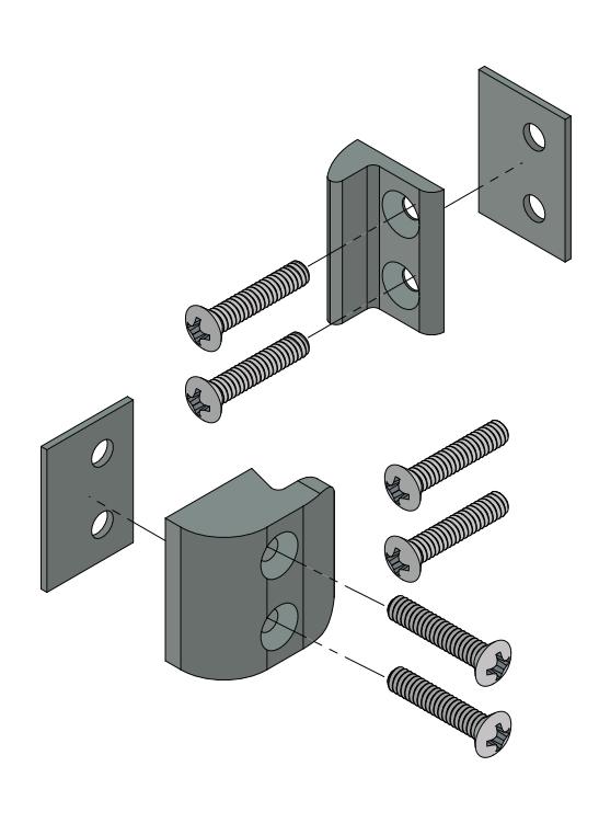
No. 30-737 Single Door 2 - Piece Stabilizer
No. 30-703 Pair of Doors 4 - Piece Stabilizer
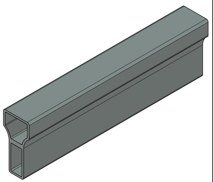
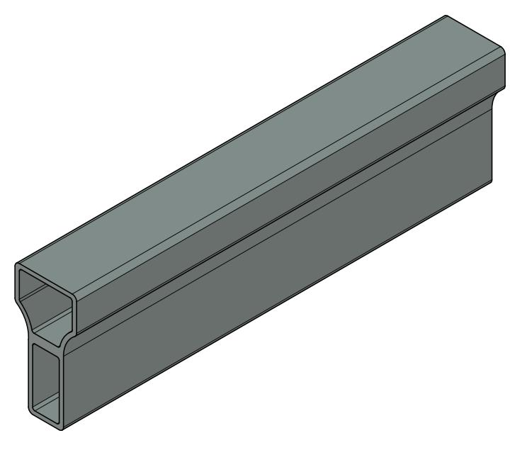
No. 30-896B8 8'-0" Blank Mullion
No. 30-896B10 10'-0" Blank Mullion
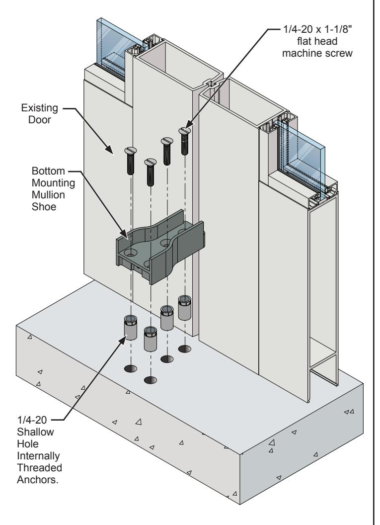
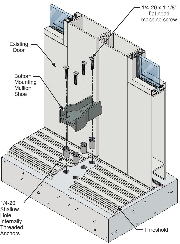
BOTTOM MOUNTING MULLION SHOE INSTALLATION
WITHOUT A THRESHOLD
- 1. Align the Bottom Mounting Mullion Shoe with the center of the door opening and flush with the closed doors and mark the hole locations.
- 2. Drill holes and install the (4) 1/4-20 Shallow Hole Internally Threaded Anchors.
- 3. Secure the Bottom Mounting Mullion Shoe with (4) 1/4-20 x 1-1/8" flat head machine screws.
WITH A THRESHOLD
- 1. Align the Bottom Mounting Mullion Shoe with the center of the door opening and flush with the closed doors and mark the shoe location.
- 2. Notch the threshold to fit the bottom shoe and mark the hole locations.
- 3. Drill holes and install the (4) 1/4-20 Shallow Hole Internally Threaded Anchors.
- 4. Secure the Bottom Mounting Mullion Shoe with (4) 1/4-20 x 1-1/8" flat head machine screws.
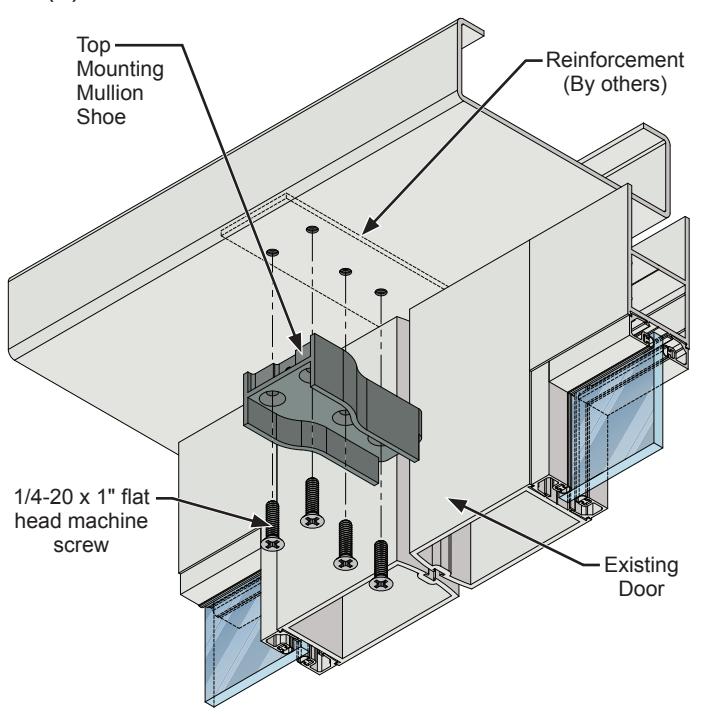
TOP MOUNTING MULLION SHOE INSTALLATION
NOTE: PROPER REINFORCEMENT TO BE SUPPLIED BY OTHERS.
HEADER OPTION #1
- 1. Align the Top Mounting Mullion Shoe with the center of the door opening and flush with the closed doors and mark the hole locations.
- 2. Drill and tap holes for (4) 1/4-20 machine screws.
- 3. Secure the Top Mounting Mullion Shoe with (4) 1/4-20 x 1-1/8" flat head machine screws.
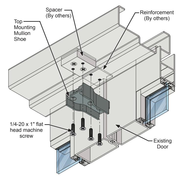
HEADER OPTION #2
- 1. Align the Top Mounting Mullion Shoe with the center of the door opening and flush with the closed doors and mark the shoe location.
- 2. Add spacer (By others) and mark the hole locations.
- 3. Drill and tap holes for (4) 1/4-20 machine screws.
- 4. Secure the Top Mounting Mullion Shoe with (4) 1/4-20 x 1-1/8" flat head machine screws.
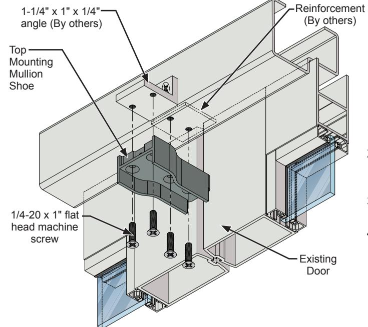
HEADER OPTION #3
- 1. Align the Top Mounting Mullion Shoe with the center of the door opening and flush with the closed doors and mark the shoe location.
- 2. Add a 1-1/4" x 1" x 1/4" angle (By others) and mark the hole locations.
- 3. Drill and tap holes for (4) 1/4-20 machine screws.
- 4. Secure the Top Mounting Mullion Shoe with (4) 1/4-20 x 1-1/8" flat head machine screws.
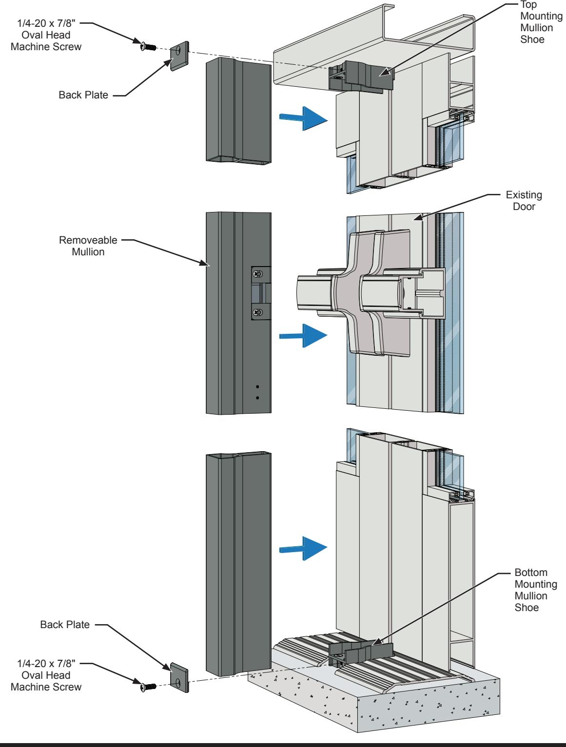
MULLION INSTALLATION
- 1. Align the Strike with the center-line of the existing Rim Panic Latch or measure from the bottom of the door according to the mounting template for the Panic Device to determine the recommended latch center-line height, Trim the Mullion as needed
- 2. Slide the mullion into the top and bottom mullion shoes.
- 3. Secure in position with the (2) back plates and (2) 1/4-20 x 7/8" oval head machine screws.
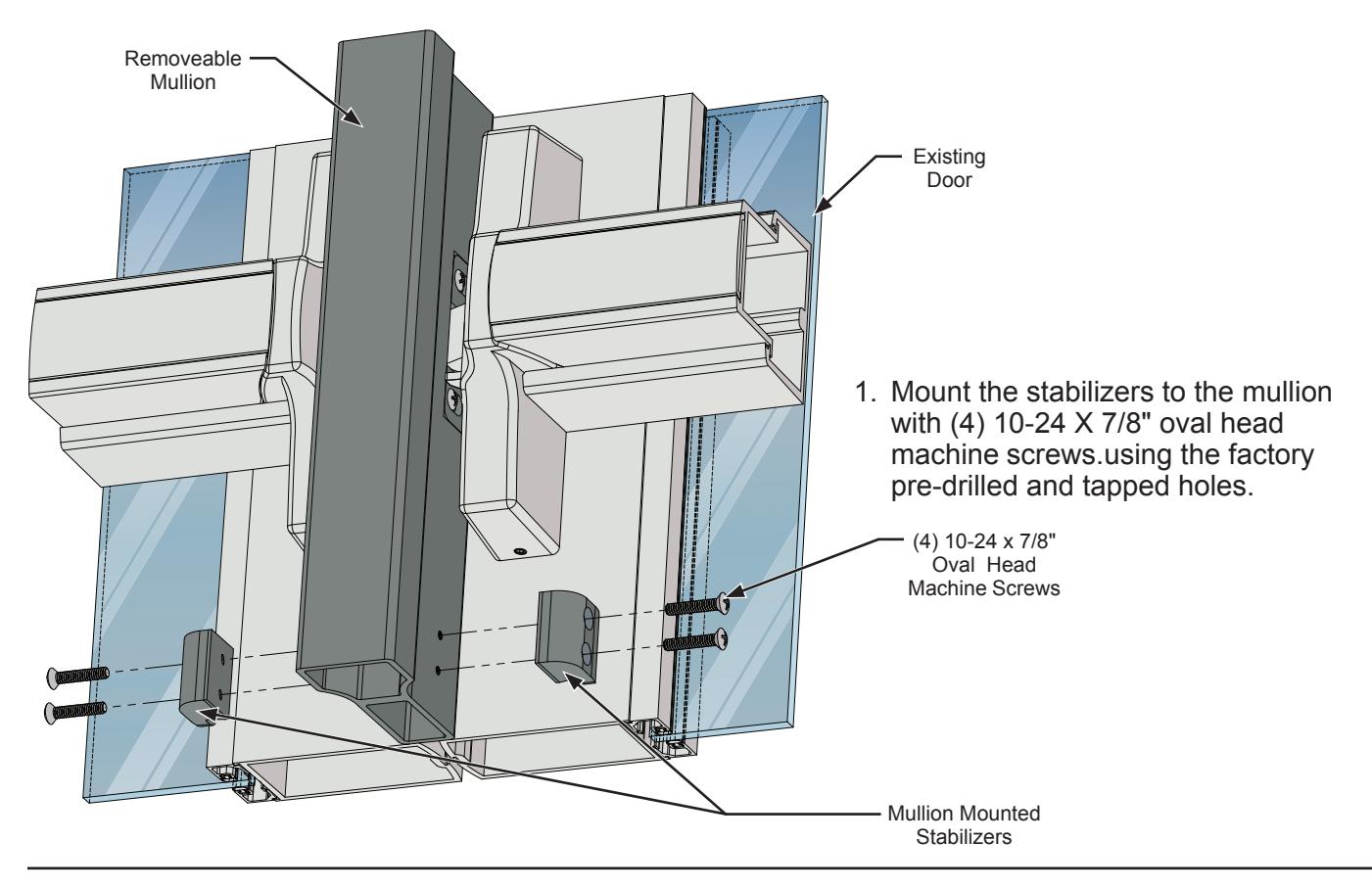
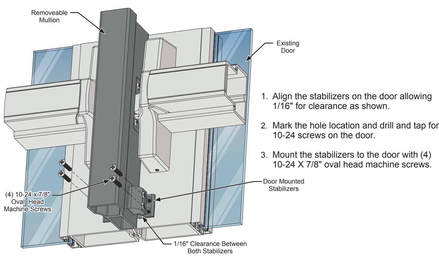
MULLION STABILIZERS INSTALLATION