Jackson 3185 Mid Panel CVR Installation Instructions
Open the original PDF document
View PDFINSTALLATION INSTRUCTIONS
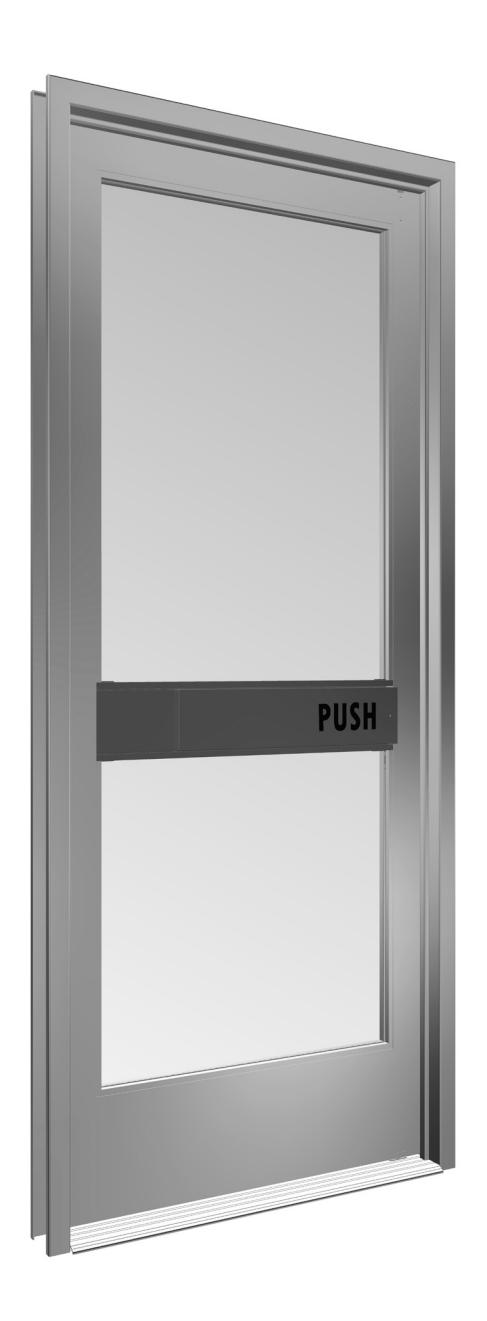
CRL JACKSON 3185 MID-PANEL CONCEALED VERTICAL ROD PANIC EXIT DEVICE

Phone: (800) 421-6144 • Fax: (866) 921-0531 crlaurence.com • usalum.com • crl-arch.com
CRL JACKSON PANIC/EXIT DEVICES-3185 CONCEALED VERTICAL ROD
ORDER OF ASSEMBLY AND INSTALLATION
|
Tools Required
|
02 |
|---|---|
|
Parts Identification
|
03 - 04 |
|
Door Preparation
|
05 - 08 |
| Remove Door | 05 |
| 3185 Bottom Guide and Upper Pullman Latch Preparation | 06 |
|
3185 Infill Actuator Cut - Out
|
07 |
| 3185 Optional Lock and Mounting Pad Preparation | 08 |
| Door Hardware Installation | 09 - 11 |
|
Insert Rod and Case
|
09 |
| Install Optional Mortise Cylinder | 10 |
|
Mid Panel Installation
|
11 |
|
Dogging Instructions
|
12 |
|
Push Bar Installation
|
13 - 14 |
| Frame Preparation | 15 - 16 |
|
Re - Attach Door to Frame
|
15 |
|
Attach Upper Strike and Bottom Strike
|
16 |
|
Door Hardware Adjustments
|
17 |
|
Packaged Parts Available
|
18 |
Tools Required
Drill bits: 1/8", 3/32", 1/2", 33/64", 1", 1-13/32" Framing square/straight edge
Tap: 10-32, 8-32 Tape measure Saw horses Drill Masking tape Center punch Flat File Round File
Phillips #2 screwdriver Jigsaw with metal cutting blade
Standard screwdriver
The rapidly changing technology within the architectural aluminum products industry demands that C.R. Laurence/U.S. Aluminum reserve the right to revise, discontinue, or change any product line, specification, or electronic media without prior written notice.
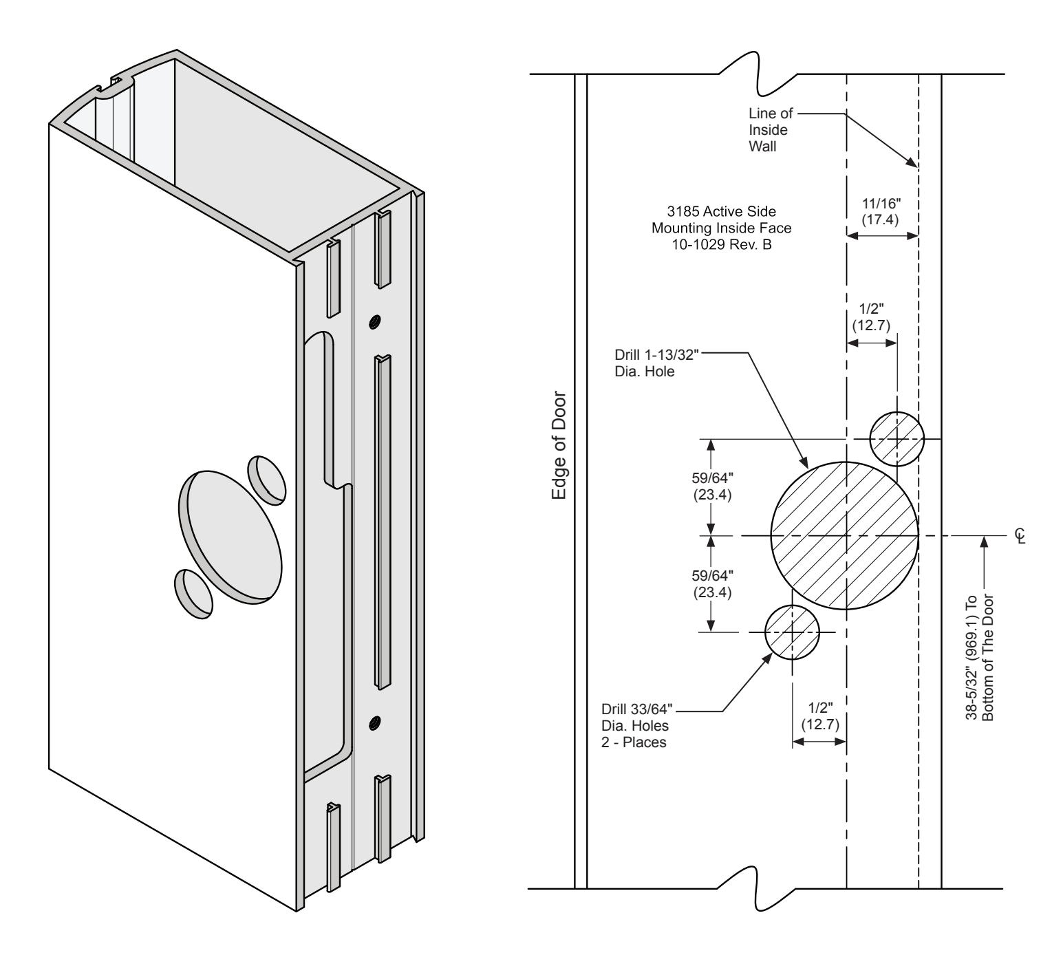
NOTE: Dimensions in parentheses ( ) are millimeters unless otherwise noted.
CRL JACKSON PANIC/EXIT DEVICES-3185 CONCEALED VERTICAL ROD
PARTS IDENTIFICATION
| FASTENERS PROVIDED | ||||||
|---|---|---|---|---|---|---|
|
CALL
OUT |
QTY. | FASTENER |
FASTENER
DESCRIPTION |
PART |
USED WITH
PART NUMBER |
|
| A | 2 |
8-32 x 1/2" Flat Head
Self Tapping Screw |
30320
Bottom Bolt Guide Assembly |
|||
| B | 2 |
10-32 x 1/4"
Flat Head Machine Screw |
302775
Upper Pullman Latch |
|||
| © | 2 |
10-32 x 3/8"
Flat Head Machine Screw |
30095/96
Locator Plate |
|||
| 0 | 2 |
8-32 x 5/16"
Set Screw |
30095/96
Lock Bar |
|||
| E | 2 |
8-32 x 1/2"
Flat Head Machine Screw |
301345
Bottom Strike Plate |
|||
| F | 4 |
8-32 x 1/2"
Flat Head Machine Screw |
301345
Upper Strike Plate |
|||
NOTE: any modifications to this product, other than those specified in this document may void the warranty as this product will no longer meet the UL safety rating requirements this product was tested and intended for.

PARTS IDENTIFICATION
| PARTS LIST | |||||
|---|---|---|---|---|---|
|
CALL
OUT |
PART | PART NO. | DESCRIPTION | ||
| G |
302831J-LHRB
302827J-RHRB |
Rod and Case Assembly | |||
| H | 30PBAW | Bolt Adjustment Wrench | |||
| I | 301552PKG | Rod Silencers (12 Pkg.) | |||
| J |
301347
301348 |
Optional 12" and 24"
Top Rod Extender |
|||
| K | DL2170 |
Optional 1" Single
Mortise Cylinder |
|||
| L | 30821B |
Optional Mortise Cylinder
Mounting Pad |
|||
DOOR PREPARATION
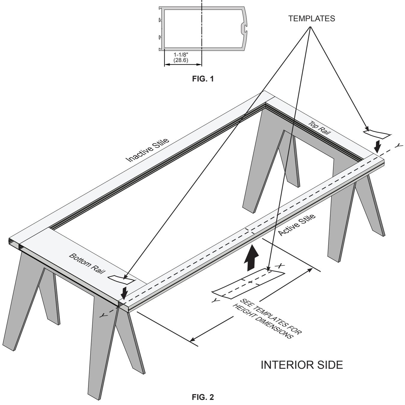
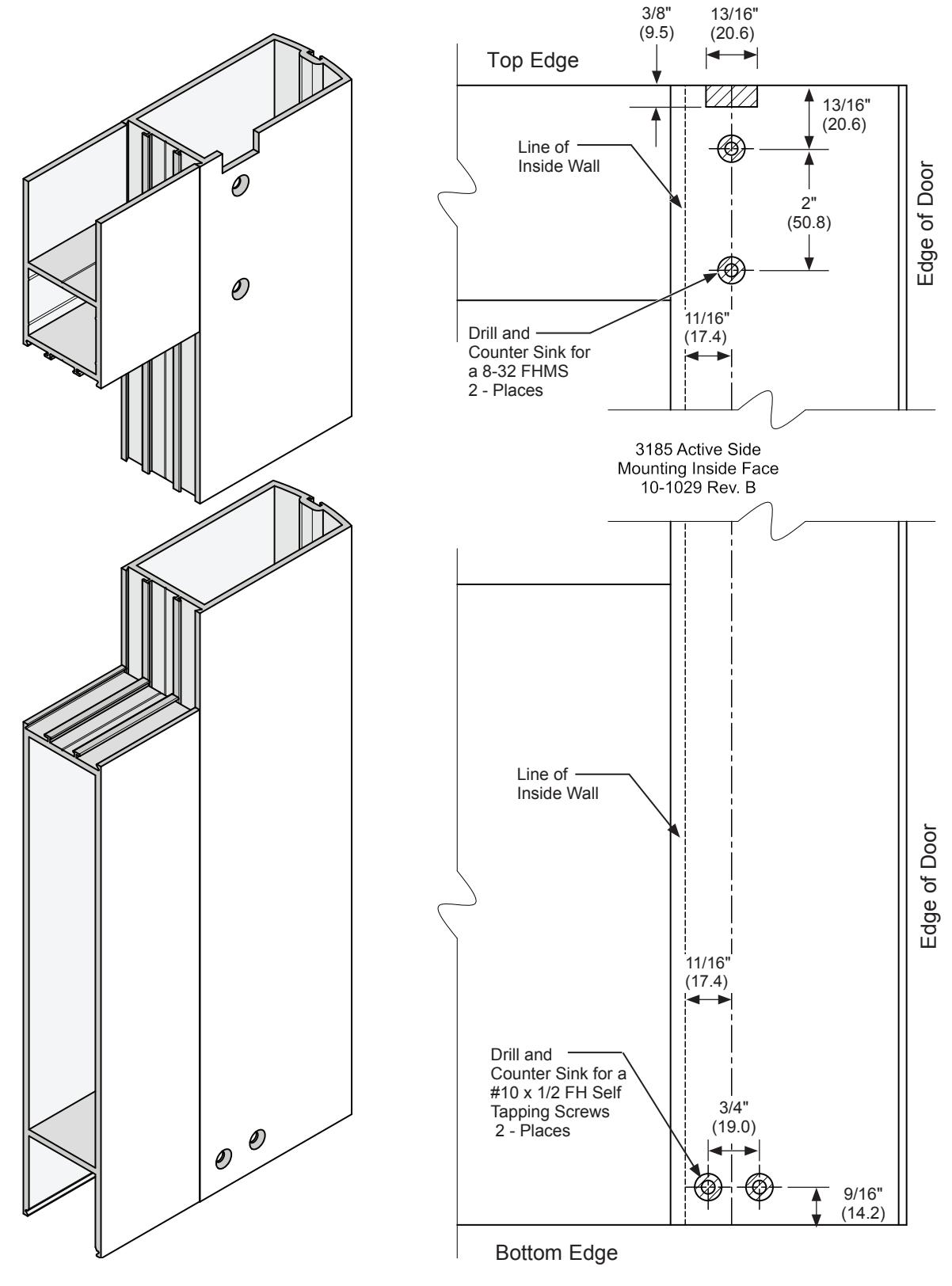
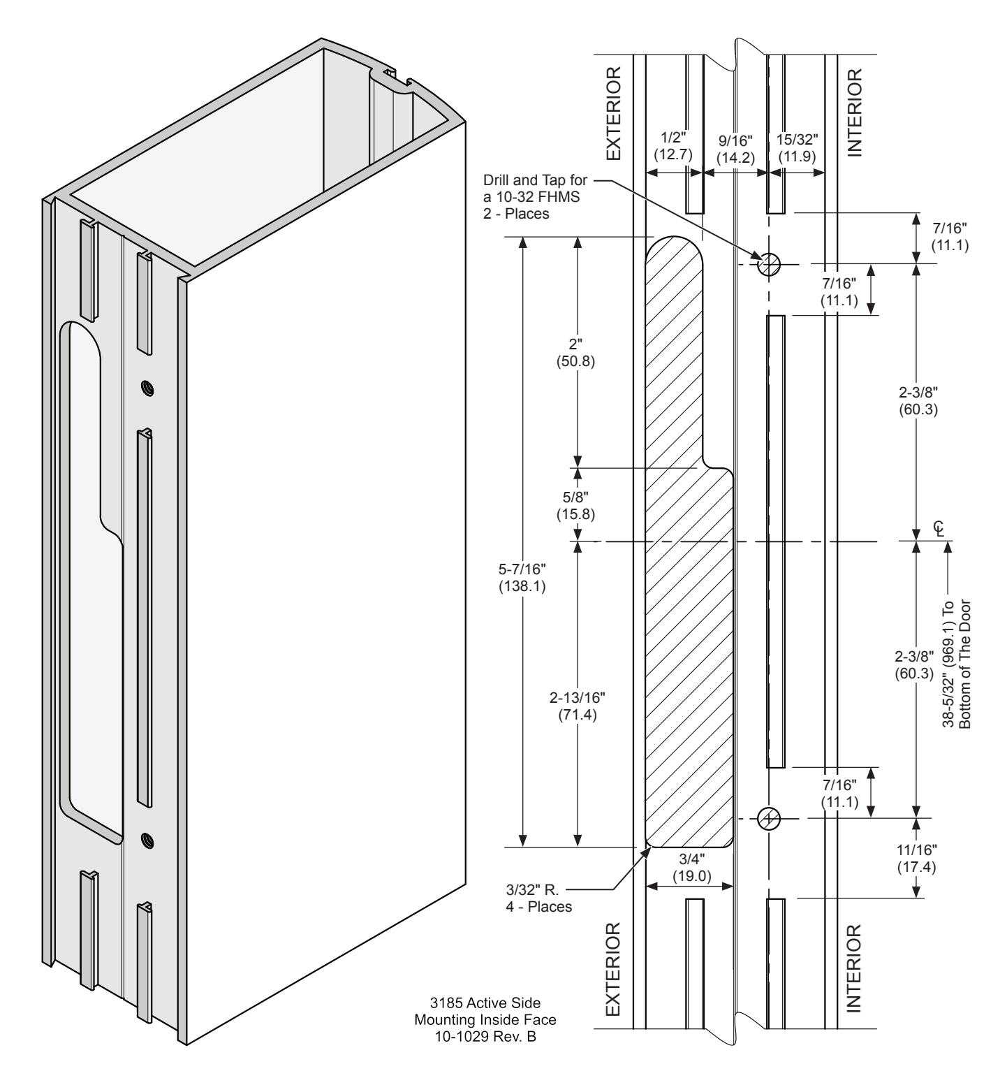
PREPARE THE DOOR PER ATTACHED LAYOUT DRAWING 10-1029
- 1. Place the door horizontally on the stands interior side up.
- 2. Mark the stile centerlines 1-1/8" (28.6) from the inside edge of the stile. ( Fig. 1 )
- 3. Mark the corresponding layouts on the stile using the vertical centerline at the specified height. ( Fig. 2 )
- 4. Attach corresponding templates. ( Fig. 2 )
NOT TO SCALE
crlaurence.com | usalum.com crlaurence.com | usalum.com05
DOOR PREPARATION – BOTTOM GUIDE AND PULLMAN LATCH
INTERIOR SIDE ON ACTIVE STILE
FIG. 3
DOOR PREPARATION – INFILL ACTUATOR CUT - OUT
SECTION SIDE ON ACTIVE STILE
FIG. 4
DOOR PREPARATION - OPTIONAL LOCK AND MOUNTING PAD
EXTERIOR SIDE ON ACTIVE STILE
FIG. 5
NOT TO SCALE
DOOR HARDWARE INSTALLATION (CONTINUED)
INSERT ROD AND CASE
- 1. Insert the panic device rod and case assembly into active stile. (Fig. 7)
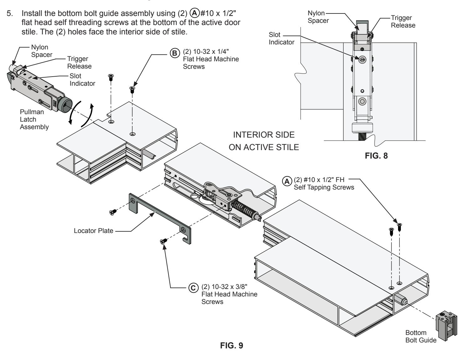
- 2. Align the rod case assembly with the locator plate and fasten with (2) 10-32 x 3/8" flat head machine screws. (Fig. 9) C
- 3. Adjust the bottom bolt, to extend 1/2" past the bottom stile.
- 4. Install the top latch assembly with the nylon spacer by rotating the latch assembly on to the rod turning it clock wise until the slot indicator aligns with the upper counter sunk hole on the door stile. (Fig. 8)
4. Remove the nylon spacer then depress the trigger release, the Pullman Latch will shift vertically approximately 1/2". The attachment holes will align with the countersunk holes on the door stile. Fasten the latch with (2) 10-32 x 1/4" FHMS B
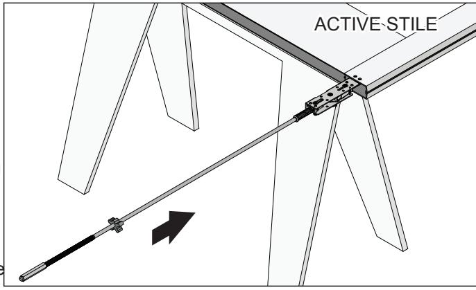
FIG. 7
NOT TO SCALE
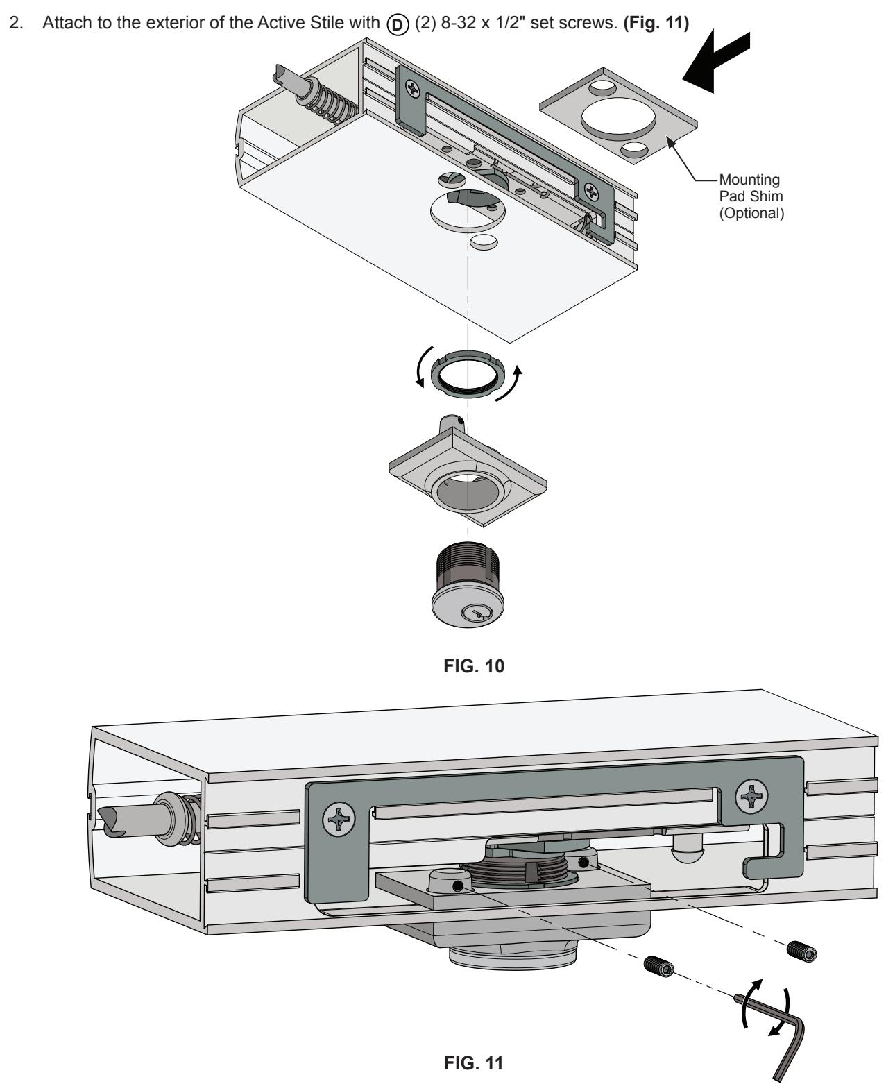
DOOR HARDWARE INSTALLATION (CONTINUED)
INSTALL THE MORTISE CYLINDER AND MOUNTING PAD
1. Insert the Mortise Cylinder into the mounting pad and secure with the Cylinder Lock Ring Included. Slide in the mounting pad shim if necessary. (Fig. 10)
NOT TO SCALE
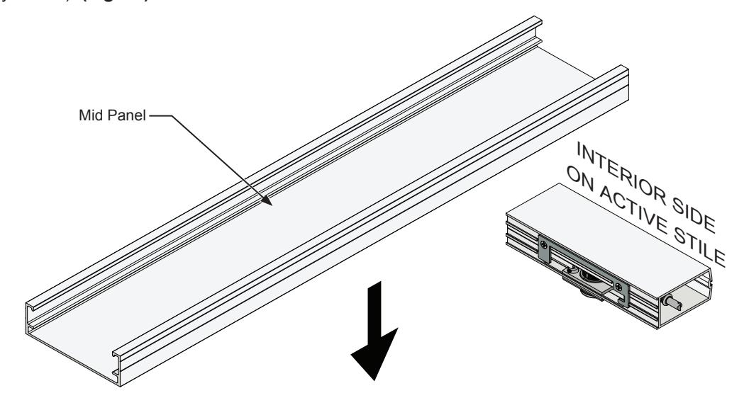
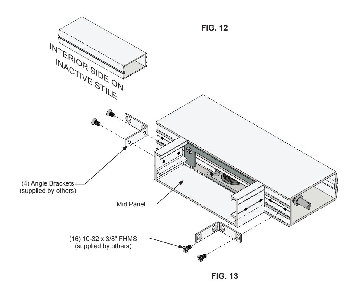
MID PANEL INSTALLATION
- 1. Install the Mid Panel. (Fig. 12)
- 2. Attach the Mid Panel to the door Stiles with (4) angle brackets (supplied by others) and (16) 10-32 x 3/8" Flat Head Machine Screws (supplied by others). (Fig. 13)
NOT TO SCALE
DOGGING INSTRUCTIONS
TO DOG: Insert 1/8" Hex Dogging key (Cat No. 302796) Press push bar, turn the key counter clockwise until it stops, pull the key out.
TO UNDOG: Insert Hex Dogging key, turn clockwise until it stops, push bar will release. Pull key out.
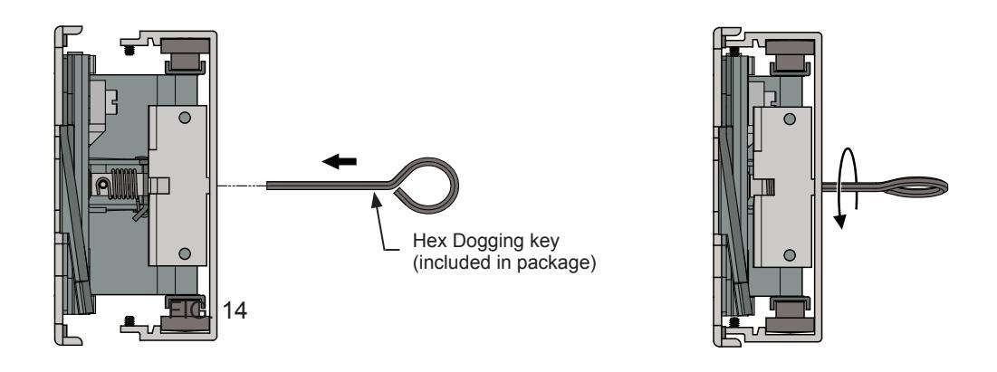
FIG. 15
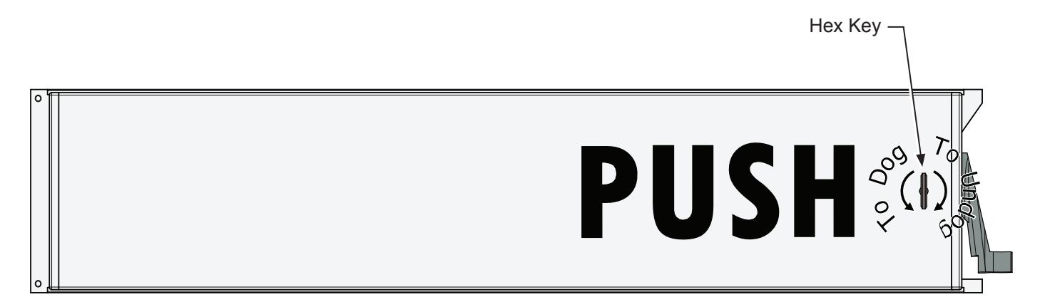
FIG. 16
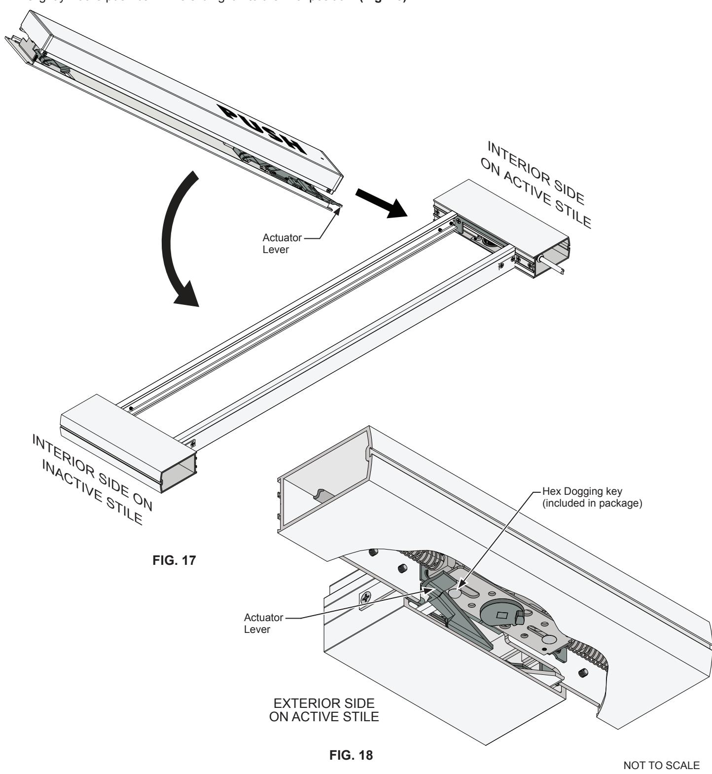
PUSH BAR INSTALLATION
- 1. Un-dog the push bar. Slide the push bar into the infill cut-out on the active door stile until the tab portion is fully secured against the active stile. (Fig. 17)
- 2. Make sure the actuator lever is positioned below the lift pin on the rod and case assembly. To achieve full engagement, slightly lift the push bar while sliding it into the final position. (Fig. 18)
PUSH BAR INSTALLATION (CONTINUED)
- 1. Install the locking bar by sliding it behind the ribbing of the mid-rail until it stops against the inactive tab. (Fig. 19)
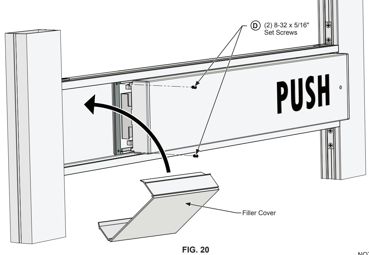
- 2. Firmly secure the locking bar with (2) 8-32 x 5/16" set screws. Install and snap in the filler cover. (Fig. 20) D
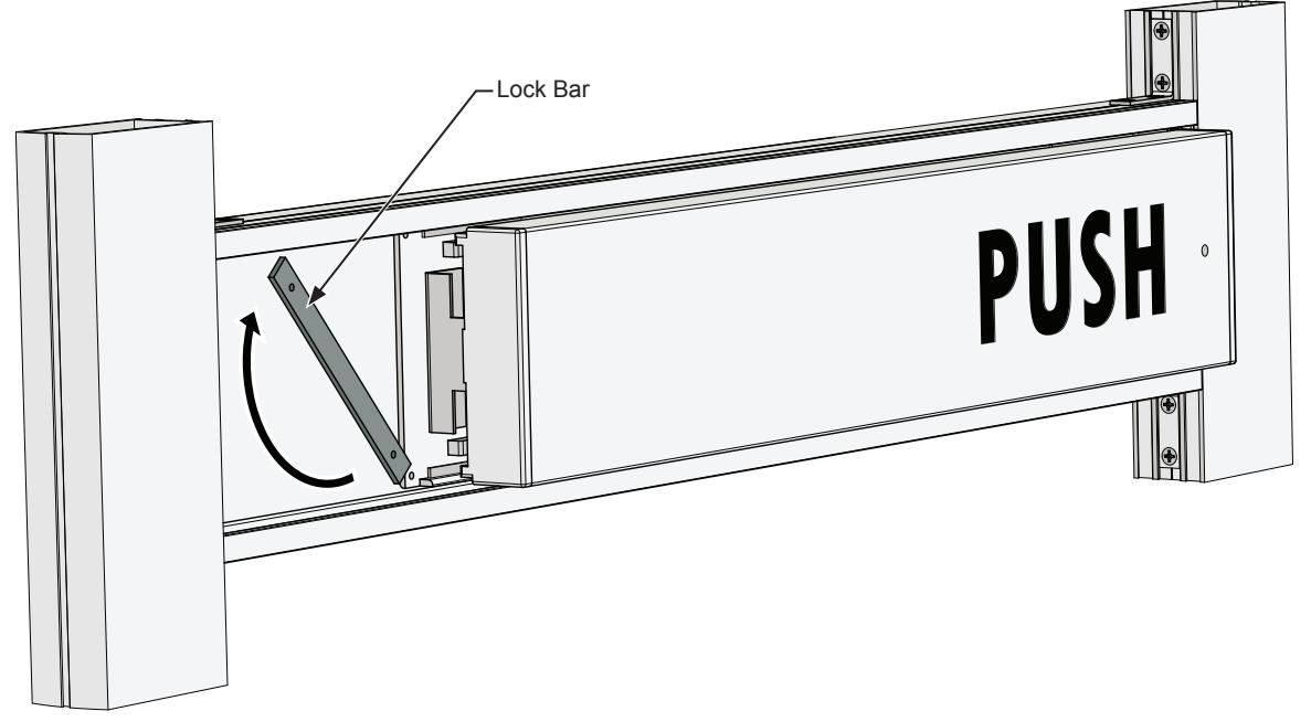
FIG. 19
NOT TO SCALE
FRAME PREPARATION
RE-ATTACH DOOR TO FRAME
- 1. Make sure that the panic exit device is in the dogged position. Both the upper and bottom latches must clear the frame. Re-attach the door to the frame.
- 2. With the door in place and in the closed position, mark the center line locations on the header and threshold of both the upper and bottom latches.
- 3. Finish the header and threshold preparation using the layout drawings on page 17.
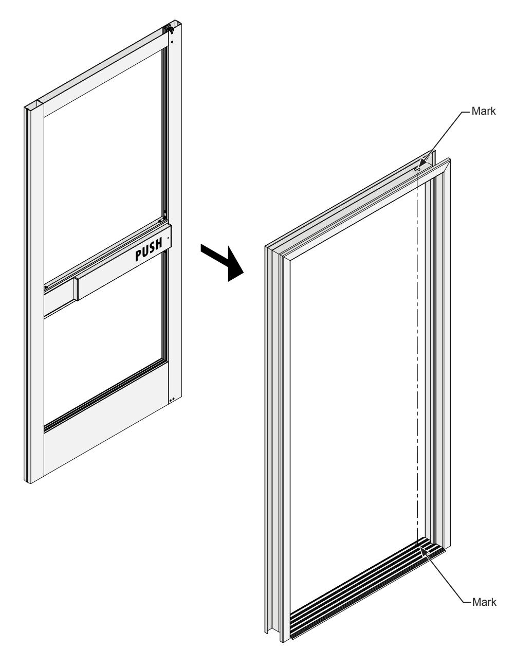
FIG. 21
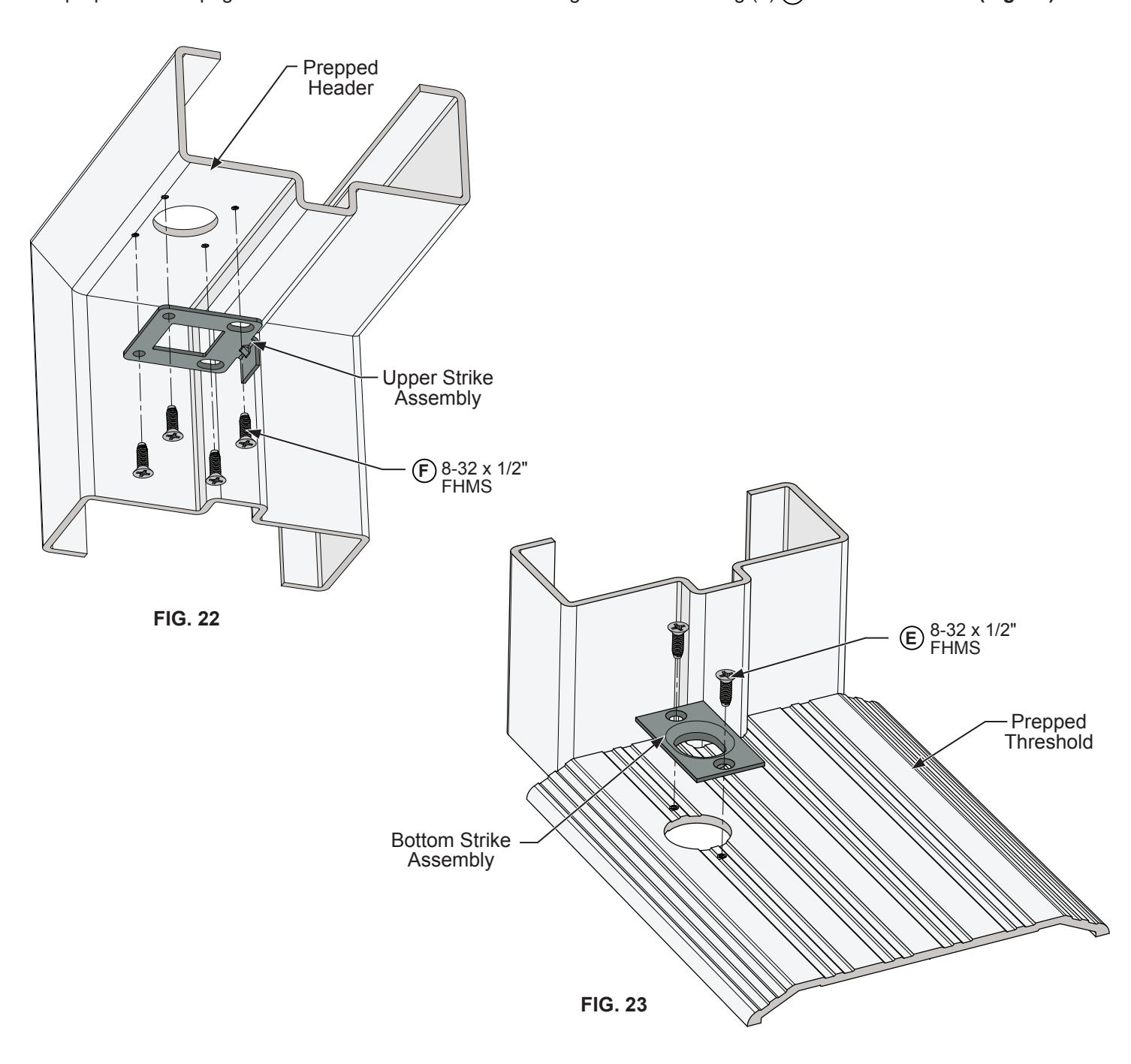
FRAME PREPARATION (CONTINUED)
ATTACH UPPER STRIKE
Drill a 1" diameter hole and drill and tap for (2) 8-32 x 1/2" FHMS on the mark made in step 2 of the frame preparation on page 16. Attach the upper strike to header using (2) 8-32 x 1/2" FHMS. (Fig. 22) F F
ATTACH BOTTOM STRIKE
Drill a 1" diameter hole and drill and tap for (2) 8-32 x 1/2" FHMS on the mark made in step 2 of the frame preparation on page 16. Attach the bottom strike centering on the mark using (2) 8-32 x 1/2" FHMS. (Fig. 23) E E
NOT TO SCALE
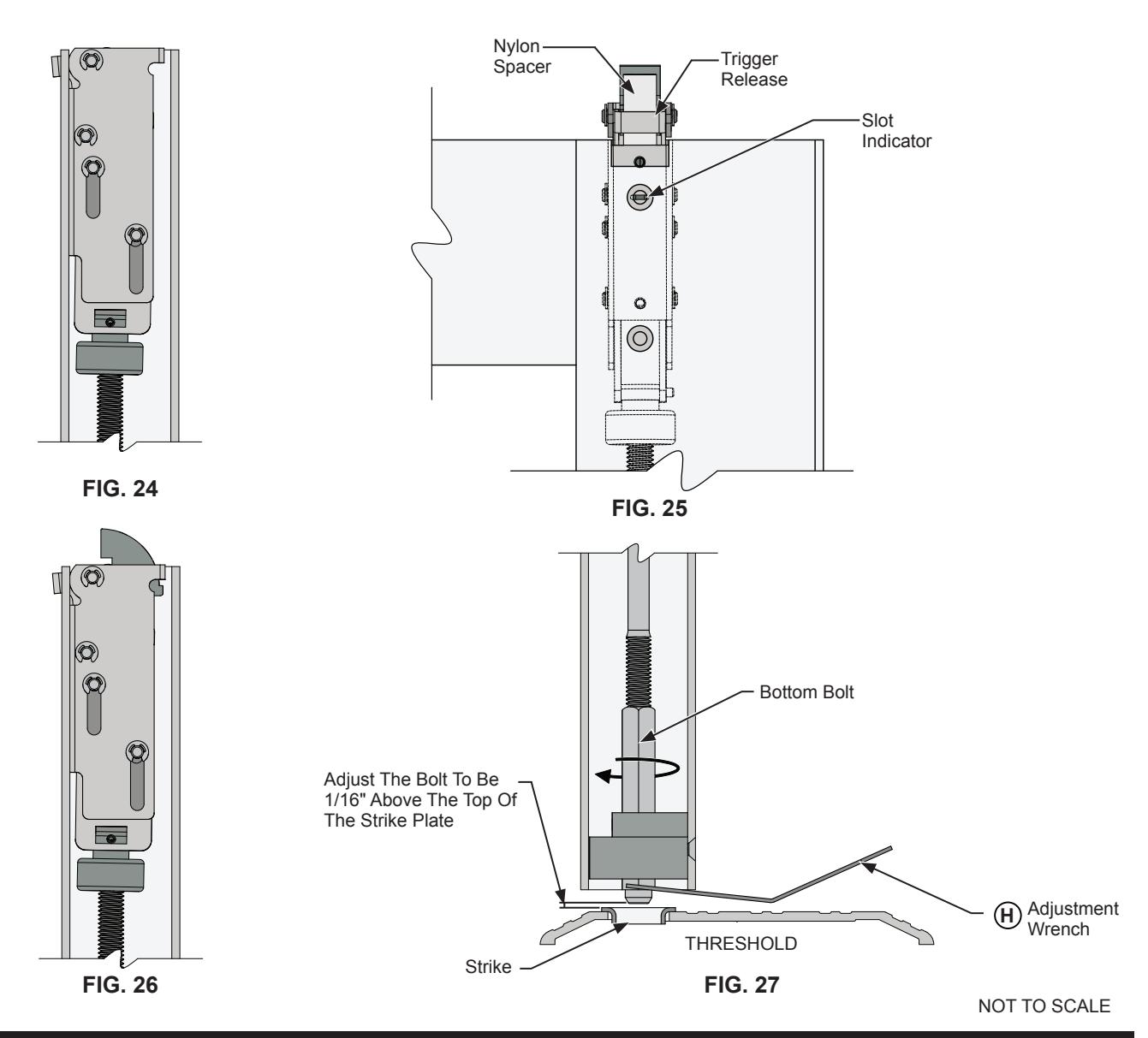
DOOR HARDWARE ADJUSTMENTS
UPPER LATCH:
- 1. The door must be in the open position and the push bar must be in the dogged position to complete the following adjustments.
- 2. Remove the (2) 10-32 x 1/4" flat head machine screws at the top of the active door stile. Rotate the upper latch one rotation clock wise or counter clock wise then pull the latch upwards to the open position. (Fig. 24) Insert the nylon spacer. Once the slot indicator aligns with the upper counter sunk hole on the door stile. (Fig. 25) Remove the nylon spacer and depress the trigger release. The latch will shift vertically 1/2". Re-attach and secure the latch case with the (2) 10-32 x 1/4" flat head machine screws. B B
BOTTOM BOLT:
- 1. The door must be in the closed position and the push bar must be in the un-dogged position to complete the following adjustments. (Fig. 26)
- 2. Depress the push bar, The bottom rod will retract and the latch will move to the unlocked position. (Fig. 24) With the latch in this position adjust the bottom bolt using the adjustment wrench included. (Fig. 27) H
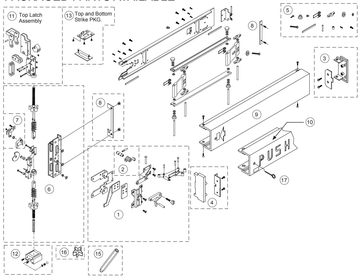
PACKAGED PARTS AVAILABLE
| Assem. No. | Part No. | Description | Assem. No. | Part No. | Description | |
|---|---|---|---|---|---|---|
| 1 | 30093 | LHRB-Actuator Head Assembly | 10 | 300041L | LHRB-Push-Pad-"Push" (Optional) | |
| Not Shown | 30094 | RHRB-Actuator Head Assembly | Not Shown | 300041R | RHRB-Push-Pad-"Push" (Optional) | |
| 2 | 30092 | Dogging Assembly | 11 | 302775 | 3185 Top Latch Assembly | |
| 3 | 30086 | Push-Pad Inactive End Cap Assembly | 12 | 30320 | Bottom Bolt Guide Assembly | |
| 4 | 30088 |
Push-Pad Active End Cap Assembly
13 301345 |
Strike Package-Top and Bottom | |||
| 5 | 30084 | Body Hardware Package | 15 | 30763P | Standard Bottom Bolt | |
| 6 | 302831J | LHRB-Rod and Case Assembly-7/0 | 16 | 301552PKG | Rod Silencers (12 Pkg.) | |
| Not Shown | 302827J | RHRB-Rod and Case Assembly-7/0 | 17 | 302796 | Dogging Hex Key Package | |
| 7 | 30090 | Rod and Case Hardware Package | Not Shown | 30PBAW | Bolt Adjustment Wrench | |
| 8 | 30095 | LHRB-Mounting Bracket Set | Not Shown | 301347 | Top Rod Extension-12" | |
| Not Shown | 30096 | RHRB-Mounting Bracket Set | Not Shown | 301348 | Top Rod Extension-24" | |
| 9 | 30023 | Push-Pad-Plain-Non-Handed | ||||