Jackson 300 Thin Slab Floor Mounted Door Closer Center Hung Installation Instructions – English
Open the original PDF document
View PDFINSTALLATION INSTRUCTIONS
CRL JACKSON 300 SERIES
THIN SLAB FLOOR MOUNTED DOOR CLOSER
CENTER-HUNG

Phone: (800) 421-6144 • Fax: (866) 921-0531 crlaurence.com • usalum.com • crl-arch.com
CRL JACKSON 300 SERIES THIN SLAB FLOOR MOUNTED DOOR CLOSER
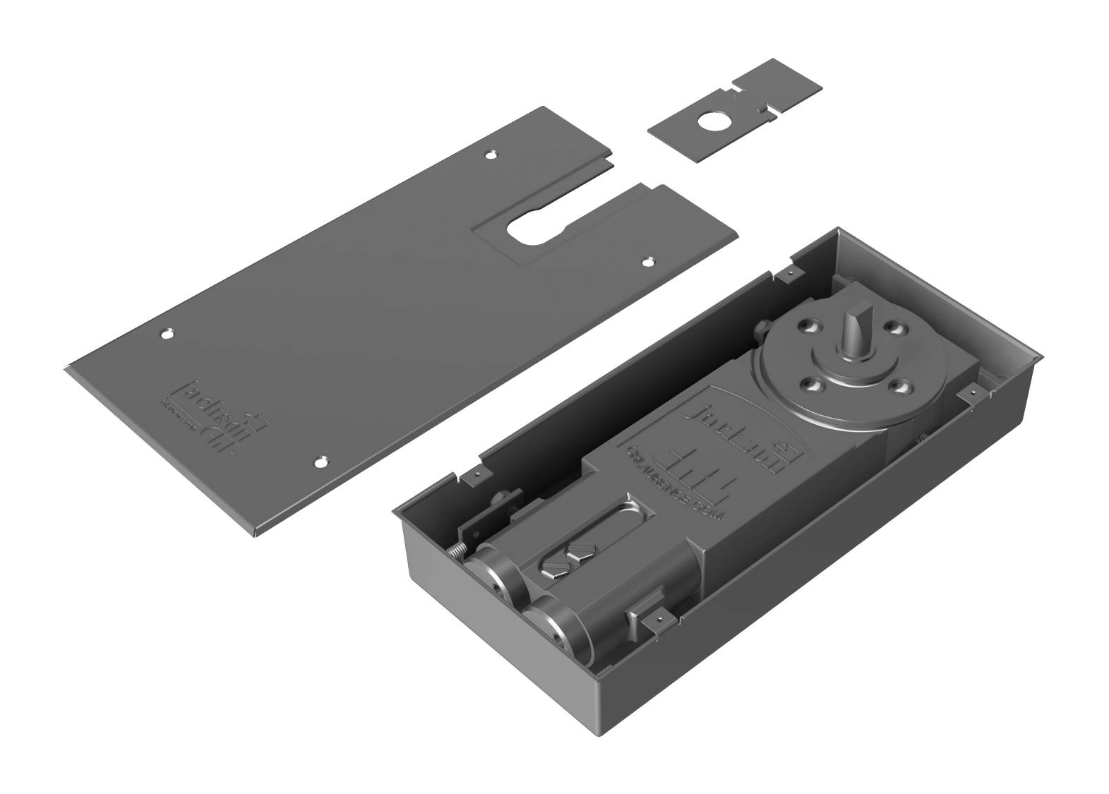
ORDER OF ASSEMBLY AND INSTALLATION
| ORDER OF ASSEMBLY AND INSTALLATION | 02 |
|---|---|
| INTRODUCTION | 03 |
| MOUNTING DIMENSIONS | 04 |
| CLOSER AND TOP PIVOT INSTALLATION | 05-06 |
| CLOSER ARM INSTALLATION | 07 |
| CLOSER ADJUSTMENTS | 08 |
INTRODUCTION
The CRL Jackson® 300 Series Thin Slab Floor Mounted Door Closer is designed to give long lasting, maintenance free performance. Its compact design and low profile makes it ideal for thin slab applications where floor depth is limited. Available in three fixed spring sizes, this closer is designed for use with aluminum, wood or hollow metal doors and frames. These double acting, non-handed closers are available in 90º or 105º hold-open or non hold open models.
Center-Hung accessories available include center hung arm, top center-hung pivot and cover plate.
WARNING: Failure to comply with the installation procedures may void the warranty.
The rapidly changing technology within the architectural aluminum products industry demands that C.R. Laurence/U.S. Aluminum reserve the right to revise, discontinue, or change any product line, specification, or electronic media without prior written notice.
NOTE: Dimensions in parentheses ( ) are millimeters unless otherwise noted.
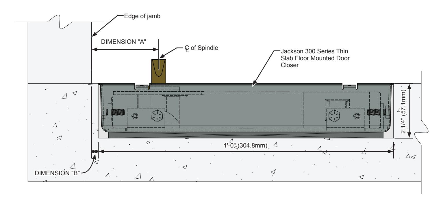
MOUNTING DIMENSIONS
| CLOSER LOCATION INSIDE HEADER | ||||||
|---|---|---|---|---|---|---|
| MODEL | DOOR TYPE | HOLD OPEN | DIMENSION "A" | DIMENSION "B" | ||
|
JACKSON
300 |
CENTER
HUNG |
90° |
2 3/4"
(69.8mm) |
7/16"
(11mm) |
||
| 105° | ||||||
CLOSER INSTALLATION
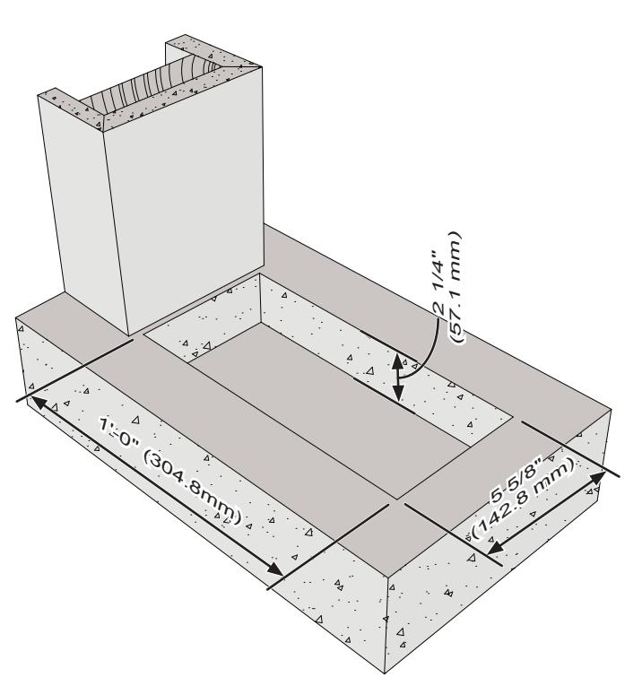
1. Cut-out a 1'-0" (304.8mm) long x 5 5/8" (142.8mm) wide x 2 1/4" (57.1mm) deep hole.
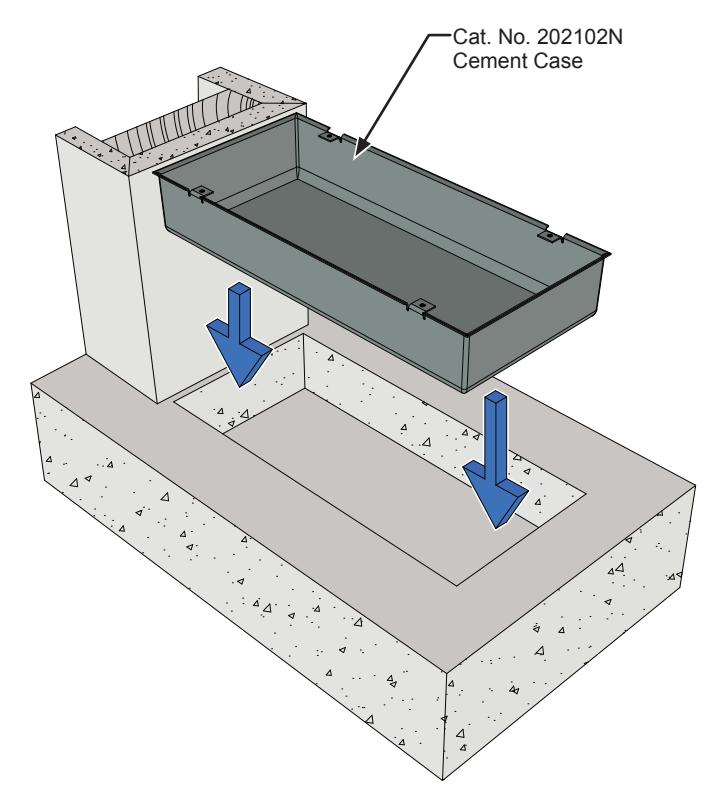
2. Place and secure the Cement Case into the hole using Rockite expanding cement.
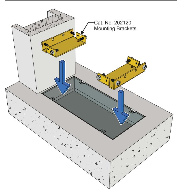
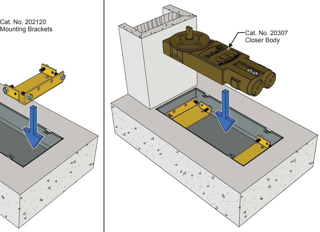
3. Insert the Adjustable Mounting Brackets. 4. Place the closer in the case and adjust the screws on the adjustable brackets to firmly secure the closer in place.
CLOSER INSTALLATION (CONTINUED)
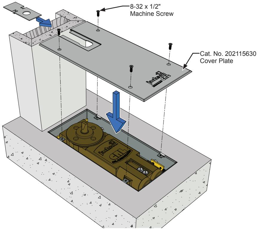
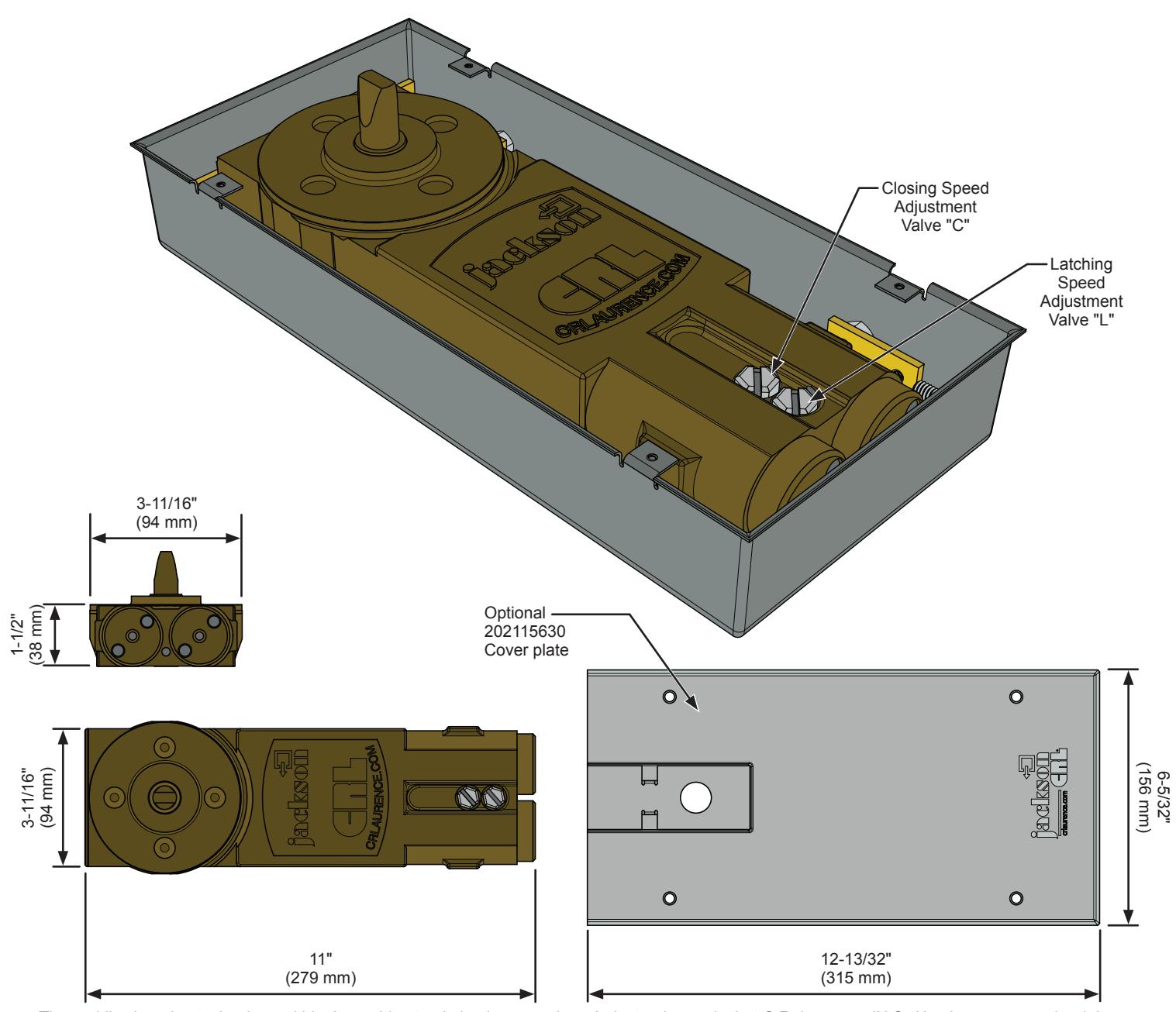
5. Fasten down the cover plate onto the cement case with (4) 8-32 x 1/2" machine screws.
WALKING BEAM PIVOT INSTALLATION
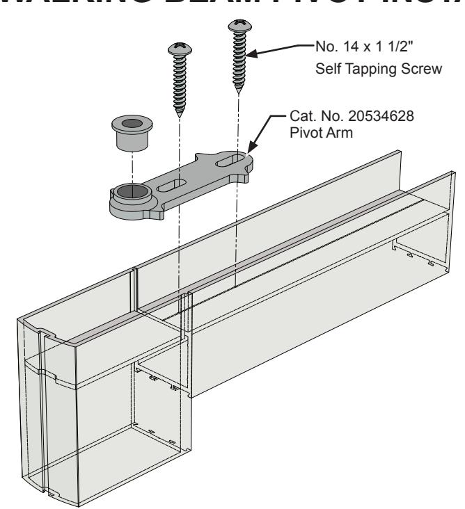
6. Secure the walking beam pivot arm to the top door rail with (2) No. 14 x 1 1/2" self tapping screws.
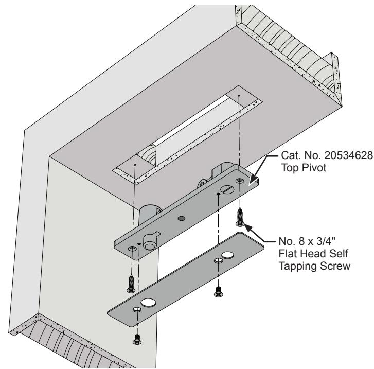
7. Secure the walking beam pivot to the header with (2) No. 8 x 3/4" flat head self tapping screws.
CLOSER ARM INSTALLATION-CAT NO. 20800628
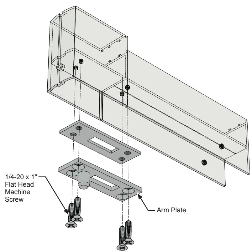
8. Secure the arm plate to the bottom door rail with (4) 1/4-20 x 1" flat head machine screws.
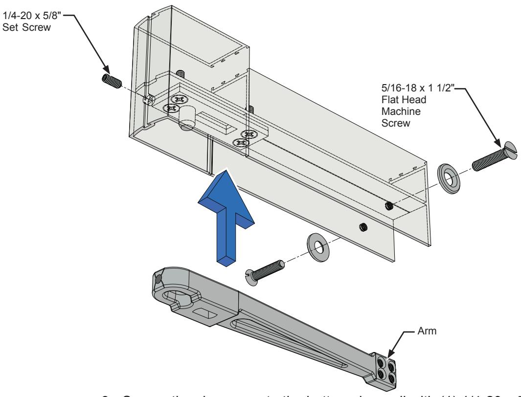
9. Secure the closer arm to the bottom door rail with (1) 1/4-20 x 5/8" set screw and (2) 5/16-18 x 1 1/2" flat head machine screws.
CLOSER ADJUSTMENT
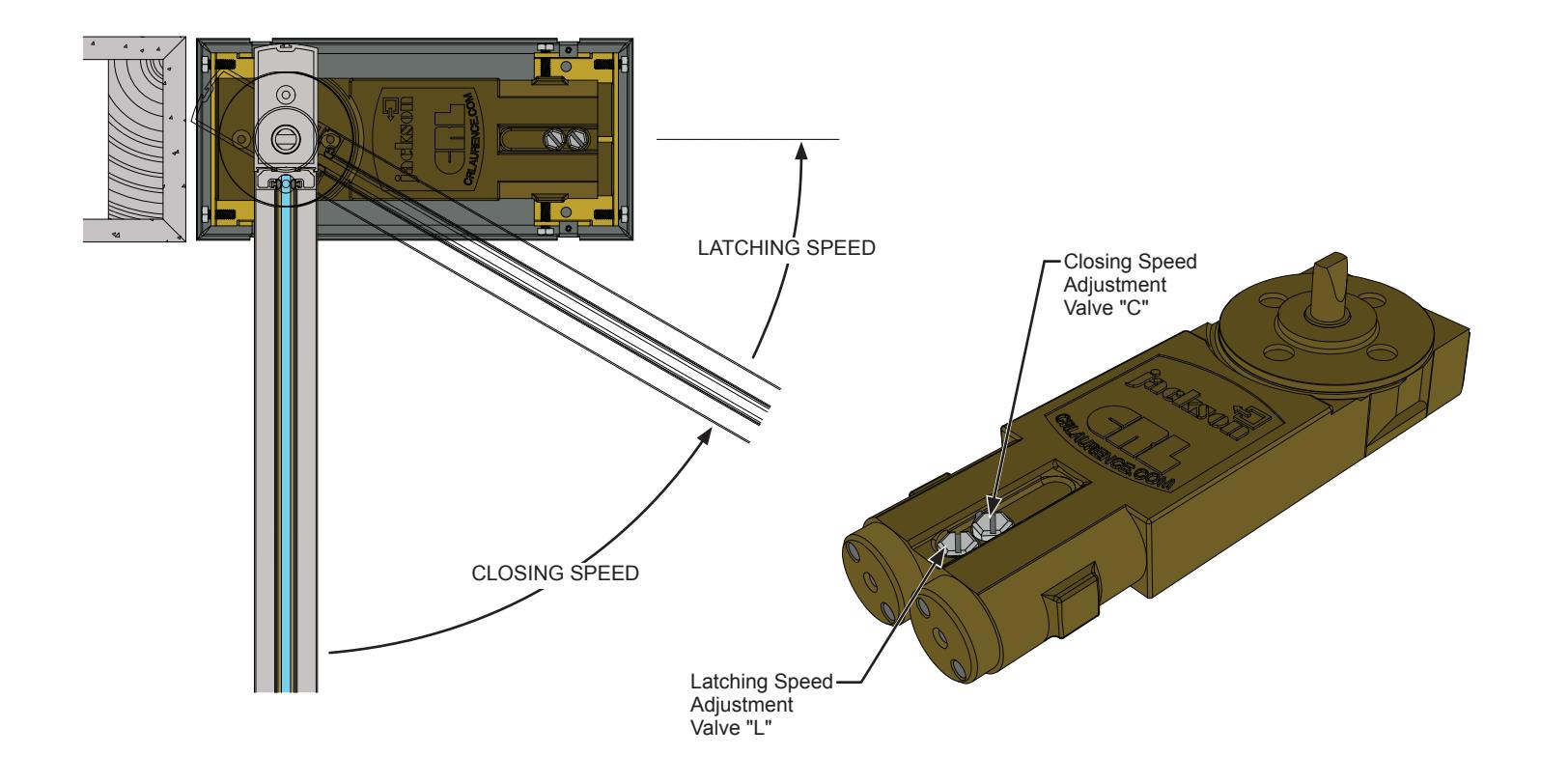
IMPORTANT: PLEASE READ BEFORE PROCEEDING. Observe all safety warnings. Always wear proper eye protection and appropriate safety equipment. WARNING: Always place a safety block between the door and the jamb to prevent the door from closing while making adjustments. WARNING: The closer contains springs compressed under high load and has no user serviceable internal components. Do not attempt to remove the covers or otherwise open the closer in any manner.
This closer has been fully tested and adjusted at the factory. The closing and latching speeds have been pre-set to achieve a 6 to 8 second closing cycle. After installation, cycle the door 10 or more times from the maximum open position to the full closed position prior to making final adjustments.
- 1. To increase either the closing or latching speeds, turn the appropriate adjustment valve counter-clockwise. To decrease either the closing or latching speeds, turn the appropriate adjustment valve clockwise.
- 2. Set the latching speed (Valve L) first, then set the closing speed (Valve C). Check and readjust if necessary.
IMPORTANT: Do not turn the adjustment valves counter-clockwise any more than necessary to achieve the proper adjustment. Excessive counter-clockwise adjustment of the valves may result in the release of fluid, rendering the closer inoperative. MAXIMUM counter-clockwise opening of the adjustment valves is 3 revolutions from full closed.
IMPORTANT: The standard internal backstop is not to be used as the primary door stop. An auxiliary floor or overhead door stop is always recommended to prevent structural interference and possible door and closer damage.