Jackson 2095E Electric Latch Retraction Panic Rim Exit Device Installation Instructions
Open the original PDF document
View PDFINSTALLATION INSTRUCTIONS
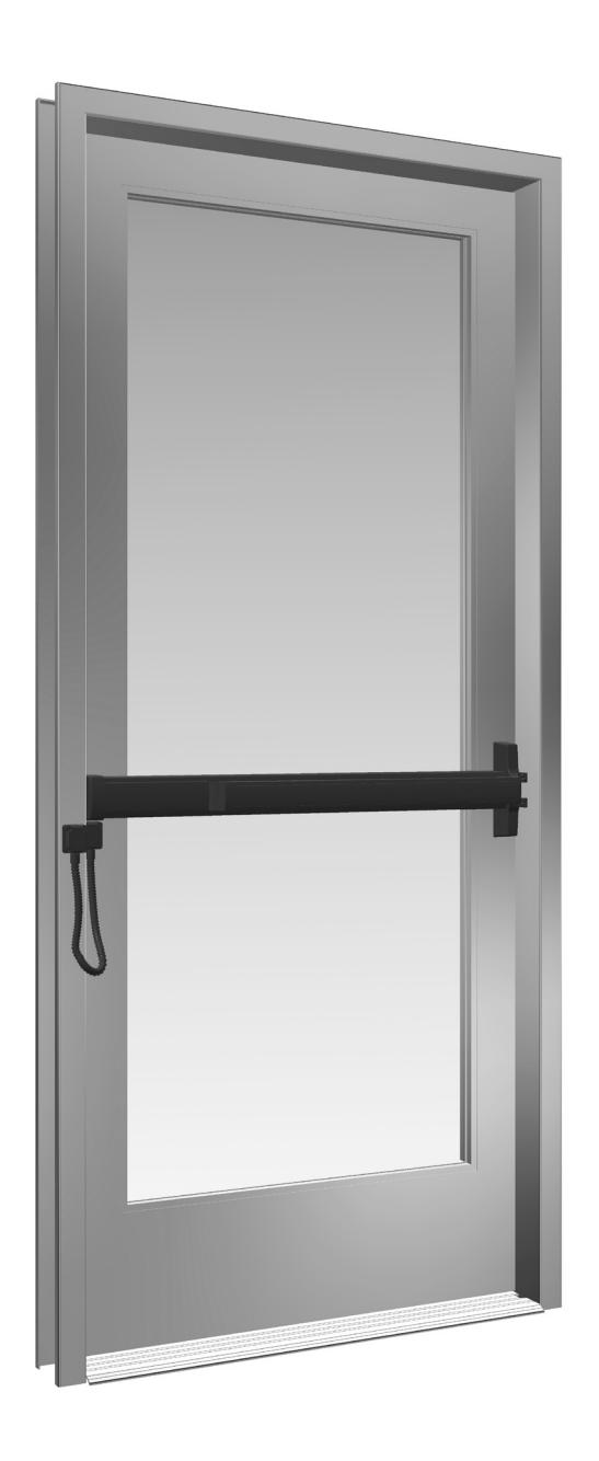
CRL JACKSON 2095E ELECTRIC LATCH RETRACTION PANIC RIM EXIT DEVICE

Phone: (800) 421-6144 • Fax: (866) 921-0531 crlaurence.com • usalum.com • crl-arch.com
ORDER OF ASSEMBLY AND INSTALLATION
| PARTS IDENTIFICATION 03 - 04 | |
|---|---|
| DOOR PREPARATION05 | |
| LAYOUT SELECTION 06 - 08 | |
| DOOR HARDWARE INSTALLATION 09 - 11 | |
| INSTALLATION OF RIM KEYED CYLINDER09 | |
| INSTALLATION OF EXTERIOR TRIM (OPTIONAL)10 | |
| INSTALLATION OF 2095E ELECTRIC RIM LATCH11 | |
| FRAME PREPARATION AND STRIKE INSTALLATION 12 - 13 | |
| ATTACH THE STRIKE13 | |
| CONNECTING THE ELECTRICAL/ELECTRICAL SCHEMATICS 14 - 16 | |
| PREPARE NON-ACTIVE DOOR JAMB SIDE17 | |
| CONNECTING ELECTRICAL COMPONENTS 18 - 19 | |
| CONNECTING THE WIRES 18 | |
| ARMORED DOOR LOOP INSTALLATION 19 | |
| PACKAGE PARTS AVAILABLE 20 |
TOOLS REQUIRED
Drill Bits: 1/8", 9/32", 5/16", 7/32", 5/8", 11/16", 1-3/8" Taps: 1/4-20, 10-32, 8-32 Tape Measure Framing Square 3/4" Masking Tape Center Punch Flat Metal File
Saw Horses Cordless Drill Round Metal File Jigsaw with Metal Cutting Blade
Phillips Head Screwdriver Straight Edge
NOTE: Any modifications, other than those specified in this document, could result in this product's failure to meet UL safety ratings and void the manufacturer's warranties.
The rapidly changing technology within the architectural aluminum products industry demands that C.R. Laurence/U.S. Aluminum reserve the right to revise, discontinue, or change any product line, specification, or electronic media without prior written notice.
NOTE: Dimensions in parentheses ( ) are millimeters unless otherwise noted.
PARTS IDENTIFICATION
| FASTENERS PROVIDED USED WITH | |||||
|---|---|---|---|---|---|
|
CALL
OUT |
QTY. | FASTENER |
FASTENER
DESCRIPTION |
PART |
PART NUMBER
AND DESCRIPTION |
| A | 2 |
1/4"-20 x 1/4"
Shoulder Stud Screws |
302622 Active
Head Assembly 302627 Active Head Cover Package |
||
| A | 1 |
1/4"-20 x 1/4"
Shoulder Stud Screw |
301266
Base End Cap Package |
||
| B | 2 |
1/4"-20 x 5/16"
Set Screw |
302622 Active
Head Assembly 302627 Active Head Cover Package |
||
| B | 1 |
1/4"-20 x 5/16"
Set Screw |
301266
Base End Cap Package |
||
| © | 2 |
#10-32 x 5/8" Oval Head
Machine Screw |
302436 "C" Type
Surface Mounted Strike |
||
| (D) | 2 |
#1/4"-20 x 1-3/4"
Breakaway Screws |
DL911 Rim
Keyed Cylinder |
||
| E | 2 | #10-32 x 2-1/8" FHMS |
9500LV01 or 9500LV02
Optional Exterior Trim with Lever Assembly |
||
| F | 8 | ADMINISTRATION |
#8 x 1-1/4" Flat Head
Sheet Metal Screw |
Optional MLDL101
Armored Door Loop Kit |
|
PARTS IDENTIFICATION
| PARTS LIST | ||||
|---|---|---|---|---|
|
CALL
OUT |
PART | PART NO. | DESCRIPTION | |
| G | DL911 | Optional Rim Cylinder | ||
| H | 302436 |
"C" Type Surface
Mounted Strike |
||
| I |
1 2 3
6 5 4 7 8 9 # 0 * |
MLD83N |
Programmable
Digital Keypad |
|
| J | 302521 |
Wood Door
Mounting Kit |
||
| K | MLDL101 | Armored Door Loop | ||
| L |
302616
301420 |
Power Supply
See Pages 14-16 for correct Power Supply |
||
| M | 301406PSC |
24VDC Power Supply
Converter Module |
||
| N | 302989 | Signal Switch Kit | ||
DOOR PREPARATION
REMOVE DOOR AND PREPARE PER TEMPLATES
- 1. Place the door horizontally on the stands interior side up.
- 2. Mark the stile centerlines 1-1/8" (28.6) from the inside edge of the stile. ( Fig. 1)
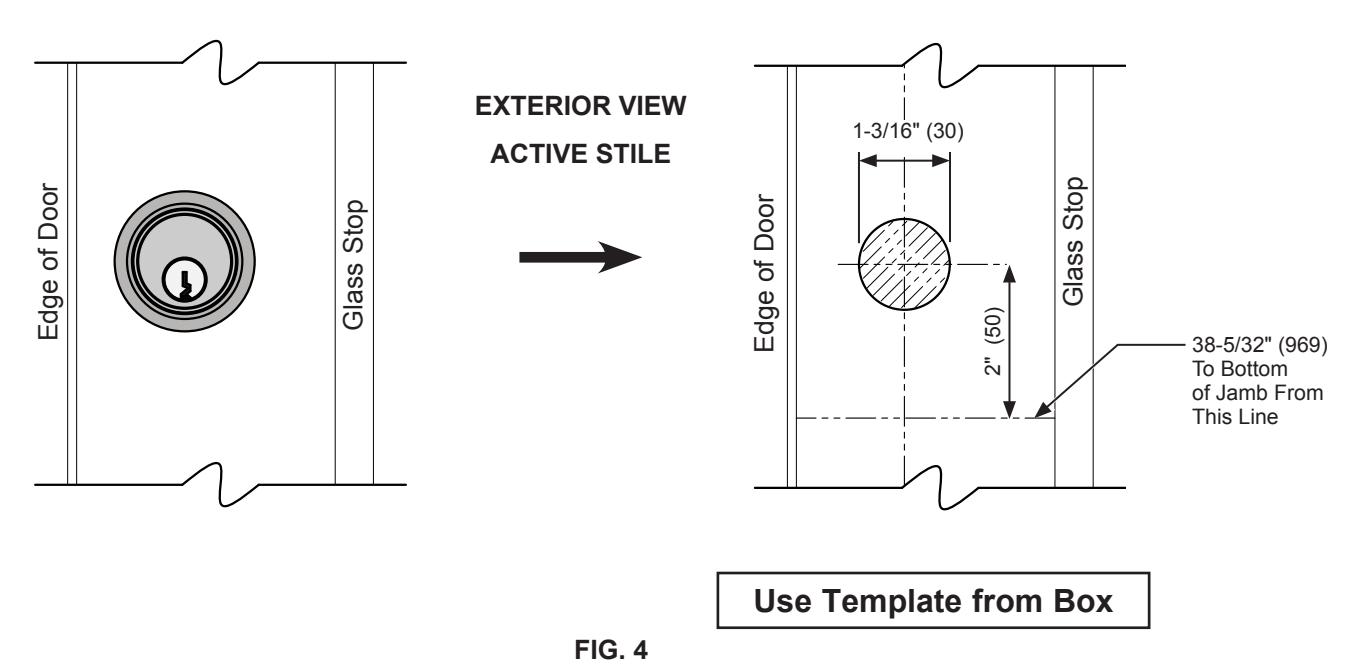
- 3. Mark the corresponding layouts on to the stile using the vertical centerlines at the specified height. ( Fig. 2)
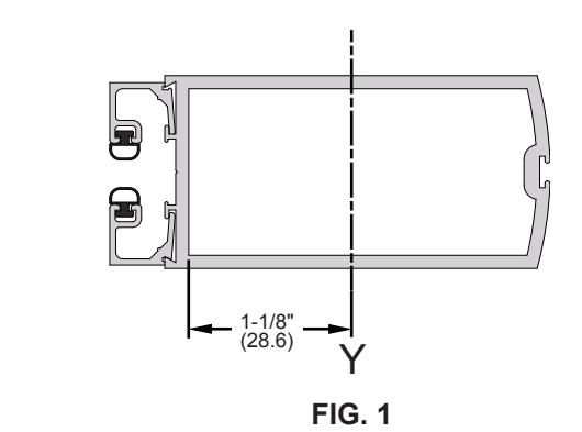
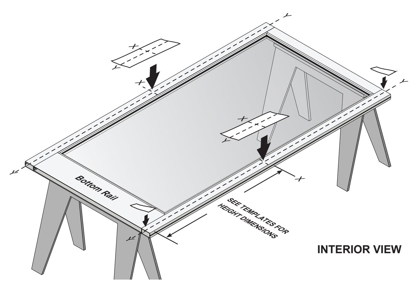
FIG. 2
DOOR PREPARATION – LAYOUT SELECTION
2095E EXIT DEVICE INSTALLATION - ACTIVE STILE
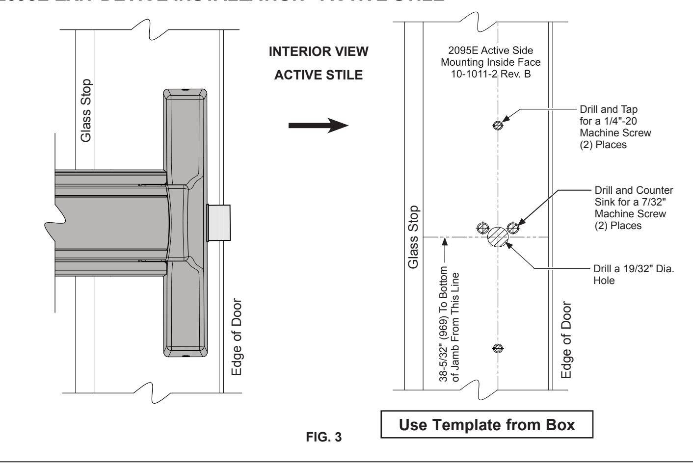
NOT TO SCALE
DOOR PREPARATION - LAYOUT SELECTION
2095E EXIT DEVICE INSTALLATION - INACTIVE STILE
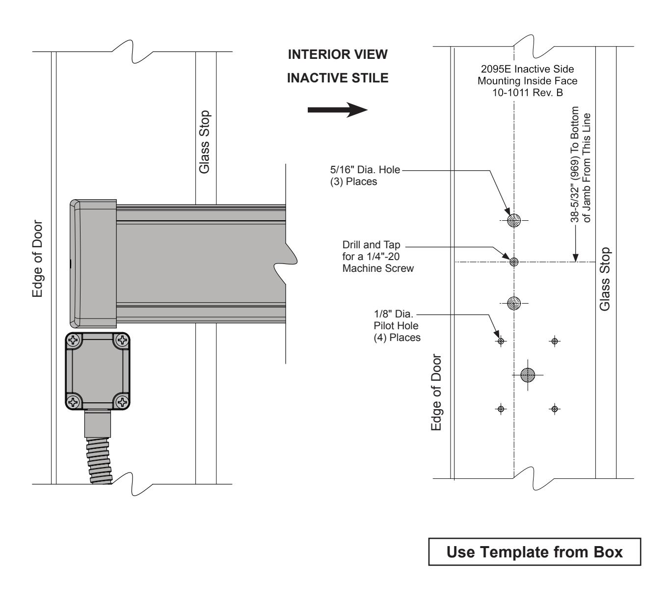
FIG. 5
NOT TO SCALE
GRL US ALUMINUM
DOOR PREPARATION – LAYOUT SELECTION
2095E EXIT DEVICE INSTALLATION WITH EXTERIOR LEVER TRIM.
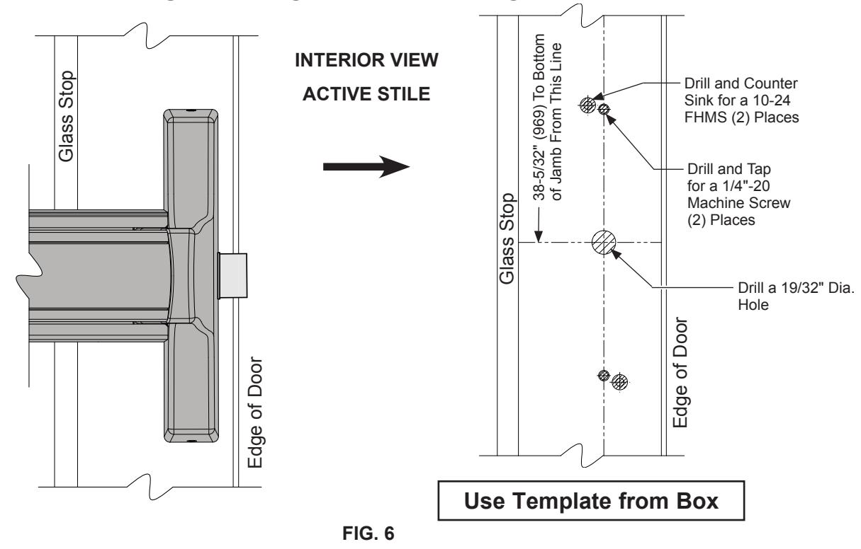
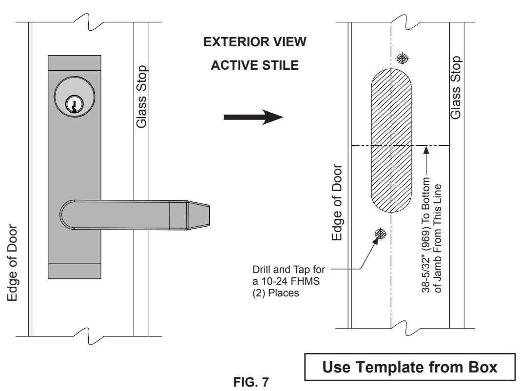
NOT TO SCALE
DOOR HARDWARE INSTALLATION
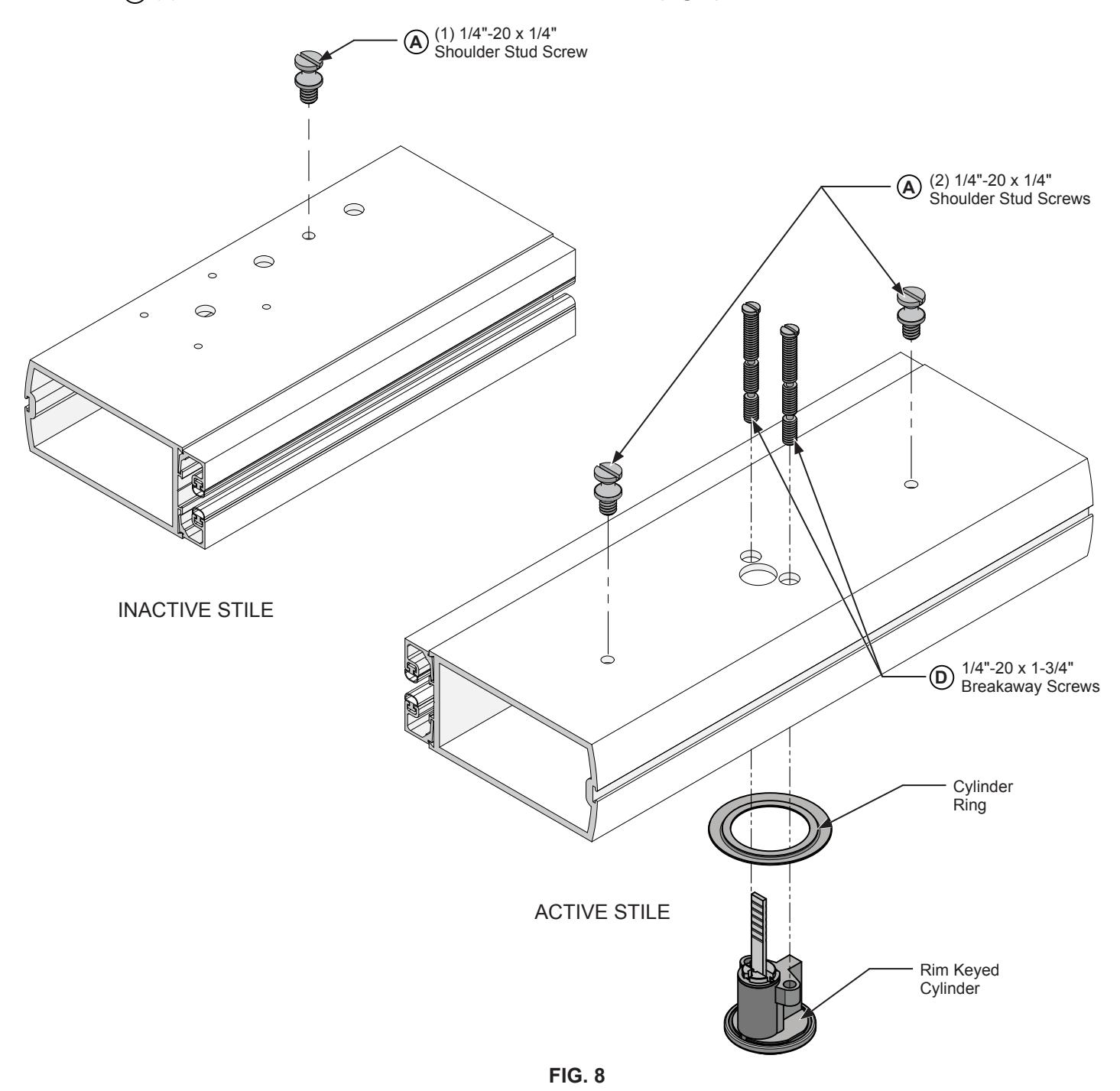
INSTALLATION OF RIM KEYED CYLINDER
- 1. Insert the rim keyed cylinder assembly into the active stile and fasten with (2) 1/4"-20 x 1-3/4" breakaway screws (Fig. 8) . D
- 2. Attach the (2) 1/4"-20 x 1/4" shoulder stud screws to the active stile. (Fig. 8) A
- 3. Attach (1) 1/4"-20 x 1/4" shoulder stud screw on the inactive stile. (Fig. 8) A
DOOR HARDWARE INSTALLATION (CONTINUED)
INSTALLATION OF OPTIONAL EXTERIOR LEVER TRIM
NOTE: Exterior trim must be installed before attaching exit device.
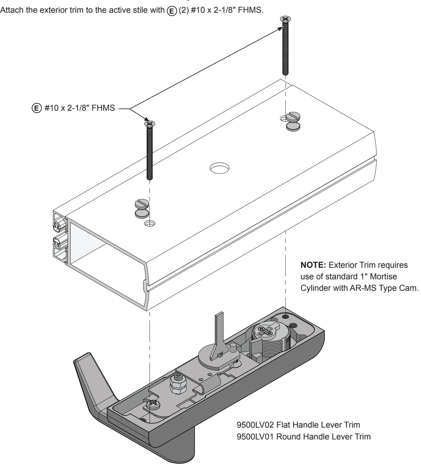
FIG. 9
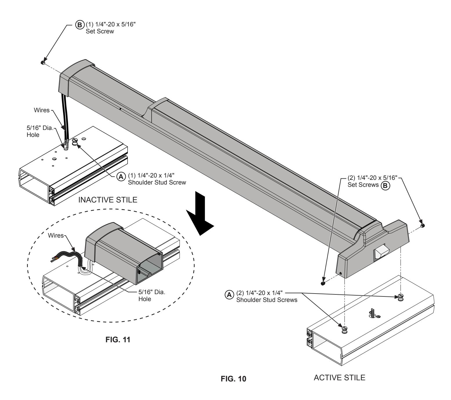
DOOR HARDWARE INSTALLATION (CONTINUED)
INSTALL 2095E ELECTRIC RIM LATCH
- 1. Insert the wires through the 5/16" Dia. hole on the inactive stile.
- 2. Install the exit device on the door stiles as you feed the wires through the upper 5/16" hole. Tighten the (1) 1/4" x 5/16" set screw and (2) 1/4" x 5/16" set screw on each side of the door stiles. (Fig. 10) B B
- 3. Pull the wires back through the lower 5/16" Dia. hole located below the exit device. (Fig. 11)
NOT TO SCALE
FRAME PREPARATION
RE-ATTACH DOOR TO FRAME
- 1. Make sure that the panic exit device is in the dogged position.
- 2. With the door in the closed position, mark the center line location of the Panic Device on the Strike Jamb.
- 3. Position the Strike over the center line and mark the screw hole locations. (Fig. 12)
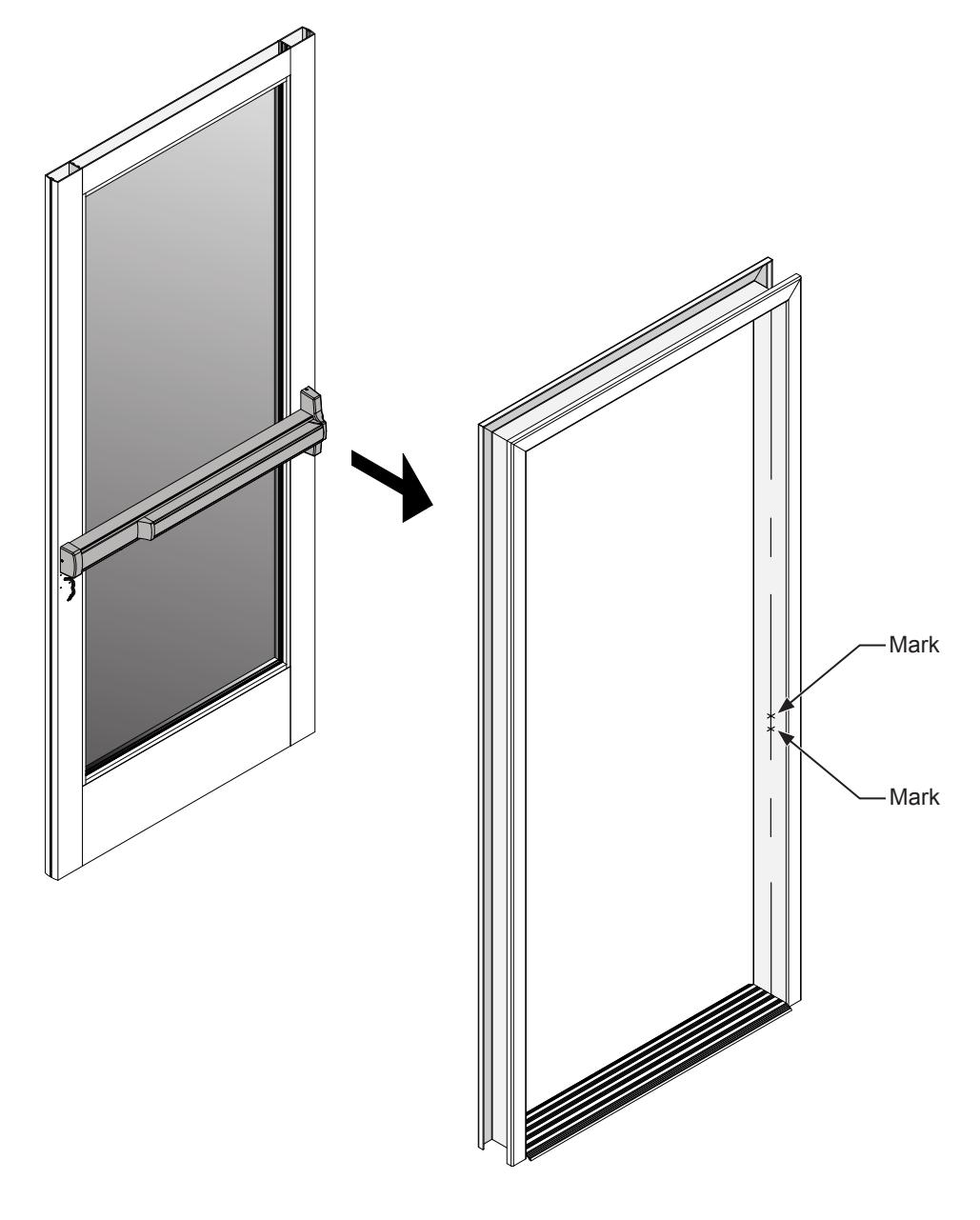
FIG. 12
FRAME PREPARATION (CONTINUED)
ATTACH THE STRIKE
Drill and tap for (2) 10-32 x 5/8" OHMS on the marks made in step 3 of the frame preparation on page 12. Attach the strike to the door jamb using (2) 10-32 x 5/8" OHMS. (Fig. 13) C C
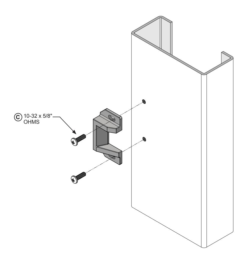
FIG. 13
CONNECTING THE ELECTRICAL
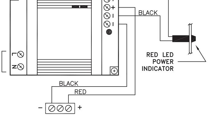
POWER SUPPLY NO. 302616/1406 ELECTRICAL SCHEMATIC
NOTE: Used with all Jackson 20E Series Electrified Solenoid Latch Retraction Panic Devices Manufactured prior to August 15, 2016.
For use with Motorized Latch Retraction manufactured after August 15, 2016, see page 15.
For Power Supply No. 301420 used with Motorized Latch Retraction, See page 16.
When the exit device works properly, connect the wires to the power supply as shown in Figure 17, once the wires are properly attached to the power supply you need to feed the proper wires through the 5/16" Dia. hole prepped on the non - active door jamb as shown on Figure 17 on Page 17.
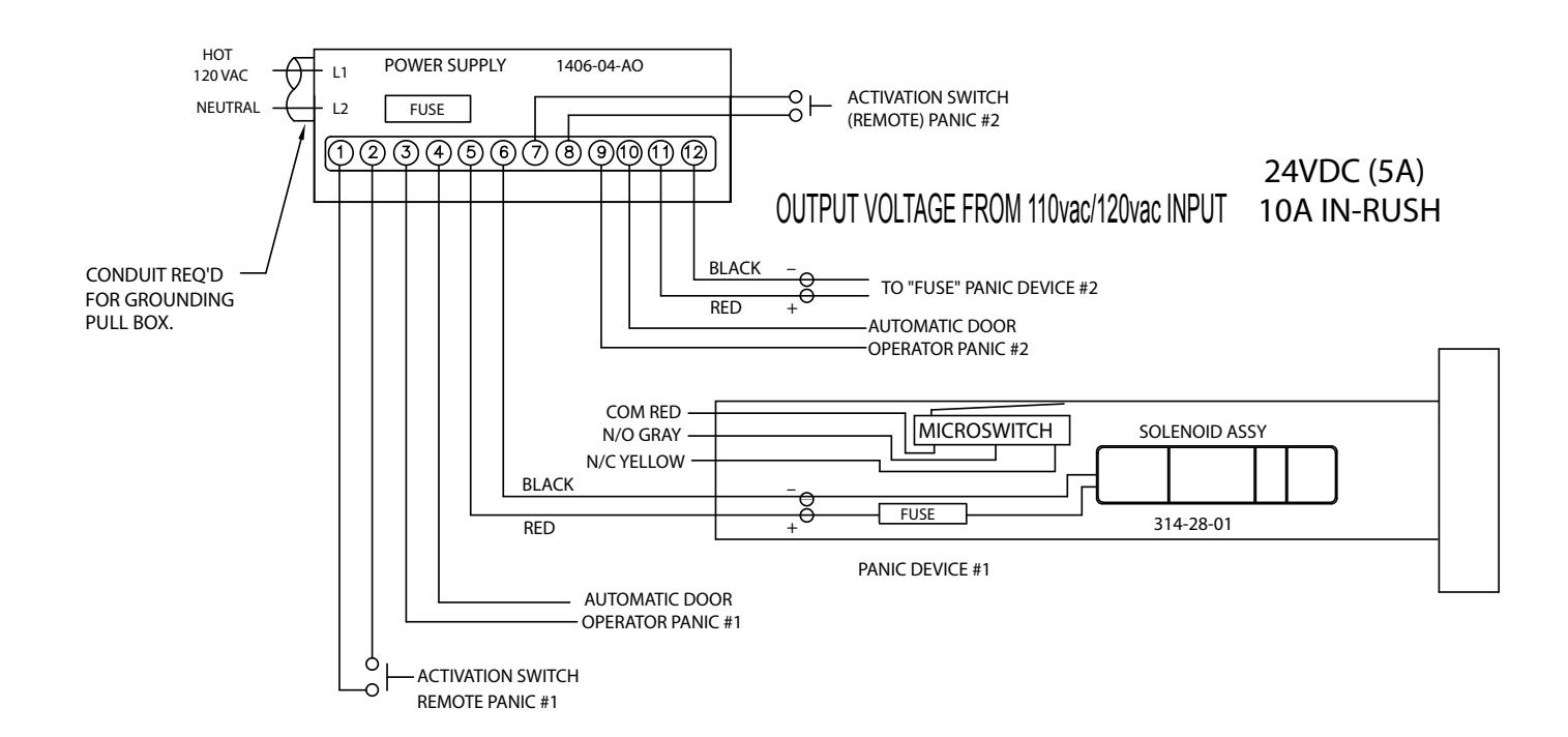
NOTES
- 1.) WHEN CONTACTS OF TIME CLOCK OR OVERRIDE SWITCH CLOSE. EXIT DEVICE LATCH BOLTS WILL CLOSE.
- 2.) DENOTES A FIELD WIRE CONNECTION.
- 3.) RECOMMENDED WIRE Ga FROM POWER SUPPLY TO PANIC:
16 Ga UP TO 40'
14 Ga UP TO 60'
12 Ga UP TO 100'
FIG. 14
CONNECTING THE ELECTRICAL (CONTINUED)
POWER SUPPLY NO. 302616/1406 ELECTRICAL SCHEMATIC
The 1406/1426-PSM-24VDC Power Supply Module converts device output voltage from Jackson 302616, ACSI Series 1406 supplies to a filtered, regulated 24VDC output for use with Jackson Series 20E Motor Drive Electric Latch Retraction Exit Devices. Up to two devices can be connected to the module's regulated output.
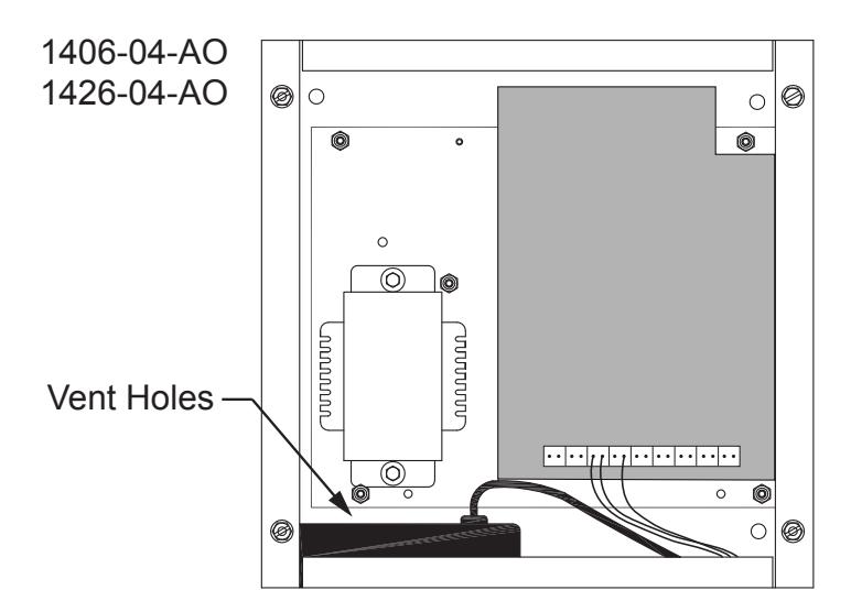
Installing the Module
The power supply module can simply be placed inside the enclosure on the bottom side at the locations shown in Figures 15. Vent holes must face upward, as indicated in Figure 15, to allow for maximum heat dissipation.
NOTE: Used with Jackson 20E Series Electrified Motorized Latch Retraction Panic Devices Manufactured after August 15, 2016, only when powered by Power Supply model No. 302616/1406
WIRE DIAGRAM
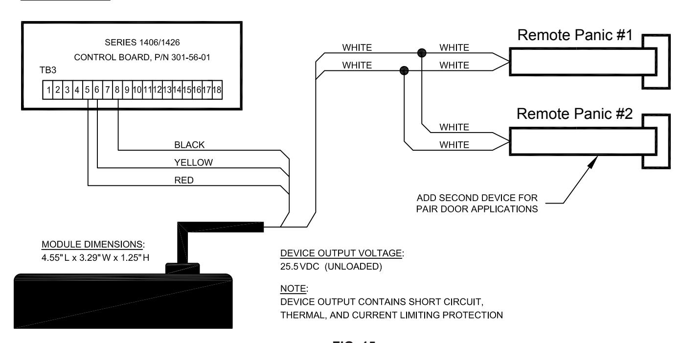
NOT TO SCALE FIG. 15
CONNECTING THE ELECTRICAL (CONTINUED)
POWER SUPPLY NO. 301420 ELECTRICAL SCHEMATIC
NOTE: Used with Jackson 20E Series Electrified Motorized Latch Retraction Panic Devices Manufactured after August 15, 2016. For Solenoid Latch Retraction Manufactured before August 15, 2016, See Page 14.

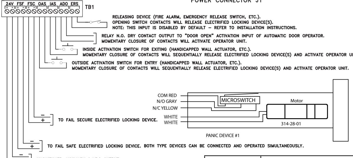
NOTES:
- 1.) The sum of all outputs cannot exceed 2 AMPS.
- 2.) When contacts of time clock or overide switch close.
- 3.) Denotes a Field Wire Connection.
- 4.) Recommended Wire Ga. from Power Supply to Panic:
FIG. 16 WIRE GAUGE MAX. LENGTH 2-COND. CABLE 22 70 FEET 20 110 FEET 18 180 FEET 15 280 FEET 14 450 FEET 12 720 FEET
PREPARE THE NON-ACTIVE DOOR JAMB SIDE
Drill a 5/16" Dia. hole and Drill (4) 1/8" Dia. pilot holes. (Fig. 17)
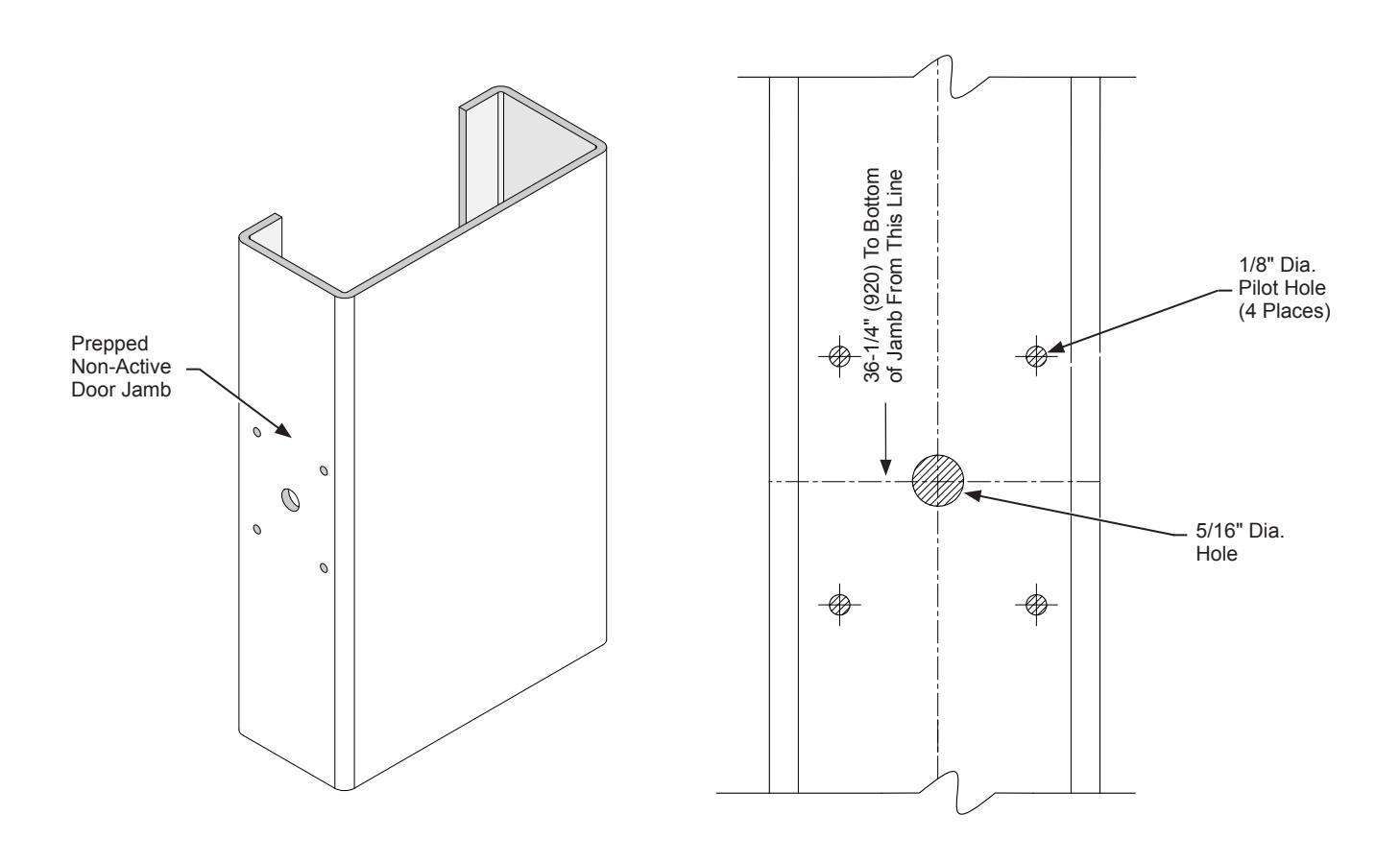
FIG. 17
CONNECTING ELECTRICAL COMPONENTS
CONNECTING THE WIRES
After preparing non-active door jamb. (Fig.17) Route the wires through the the hole on the door jamb. (Fig. 18) Next feed the wires through the Armored Door Loop, and secure the Armored Door Loop to the door jamb using (4) #8 x 1-1/4" FHSMS. (Fig. 19) F
Once you have secured the Armored Door Loop, connect the wires from the Armored Door Loop to the exit device wires using Twist-On Wire connectors. (Fig.19)
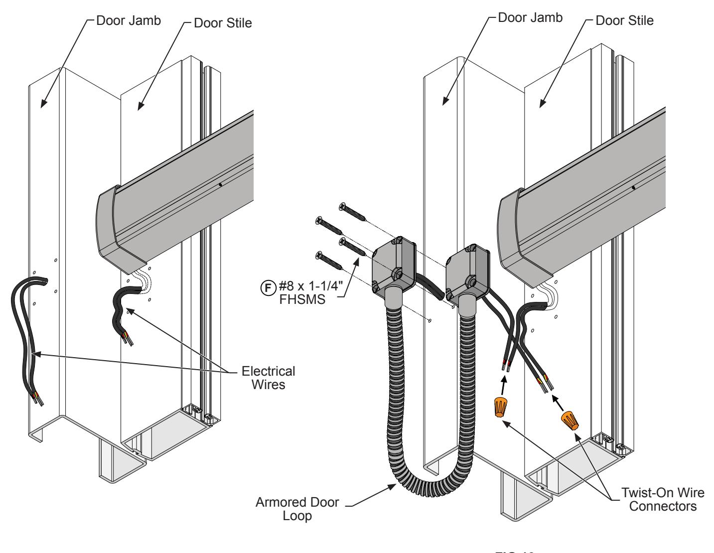
FIG.19 FIG. 18
CONNECTING ELECTRICAL COMPONENTS (CONTINUED)
ARMORED DOOR LOOP INSTALLATION
After the wires are connected, slip the remaining slacking wires and twist-on connectors back into the door stile and into the pocket of the door loop. (Fig 20) Secure the door loop to the door stile using (4) #8 x 1-1/4" FHSMS. F (Fig. 21)
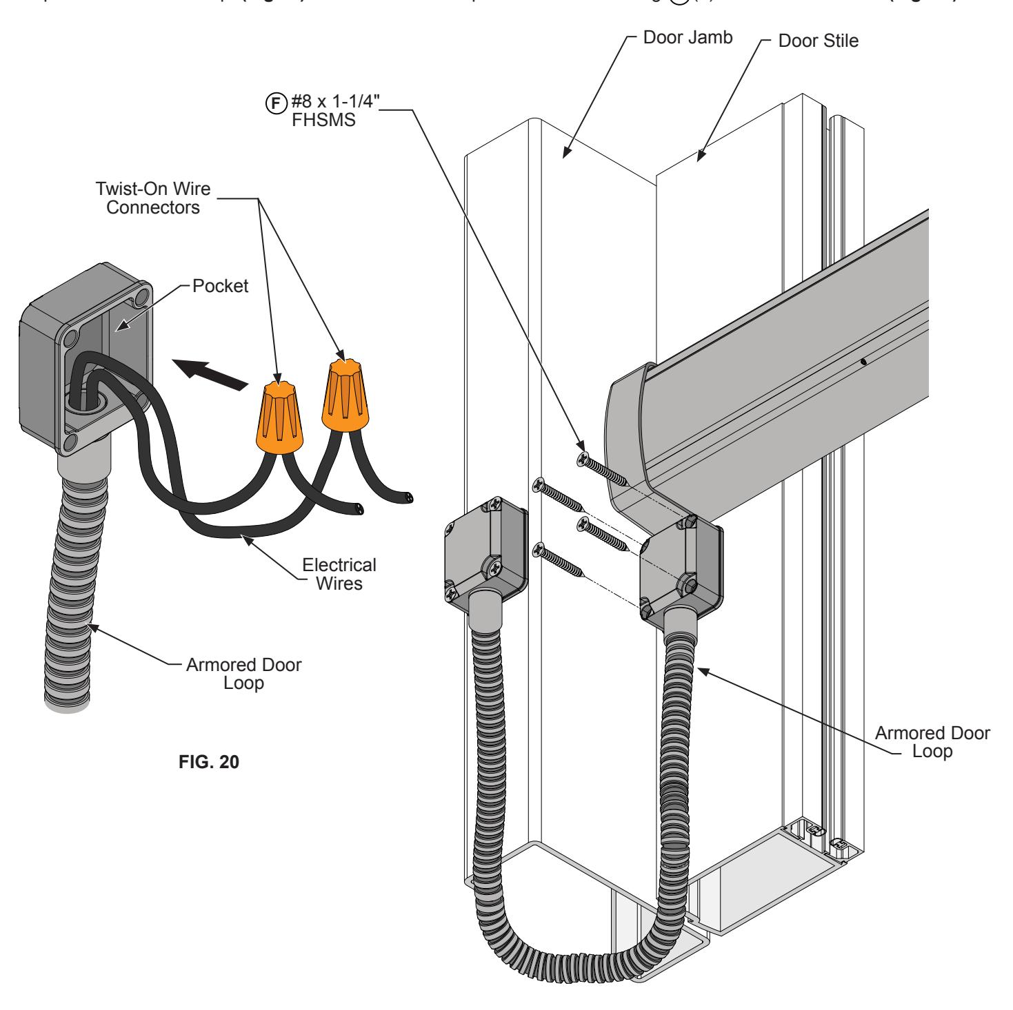
FIG. 21
NOT TO SCALE
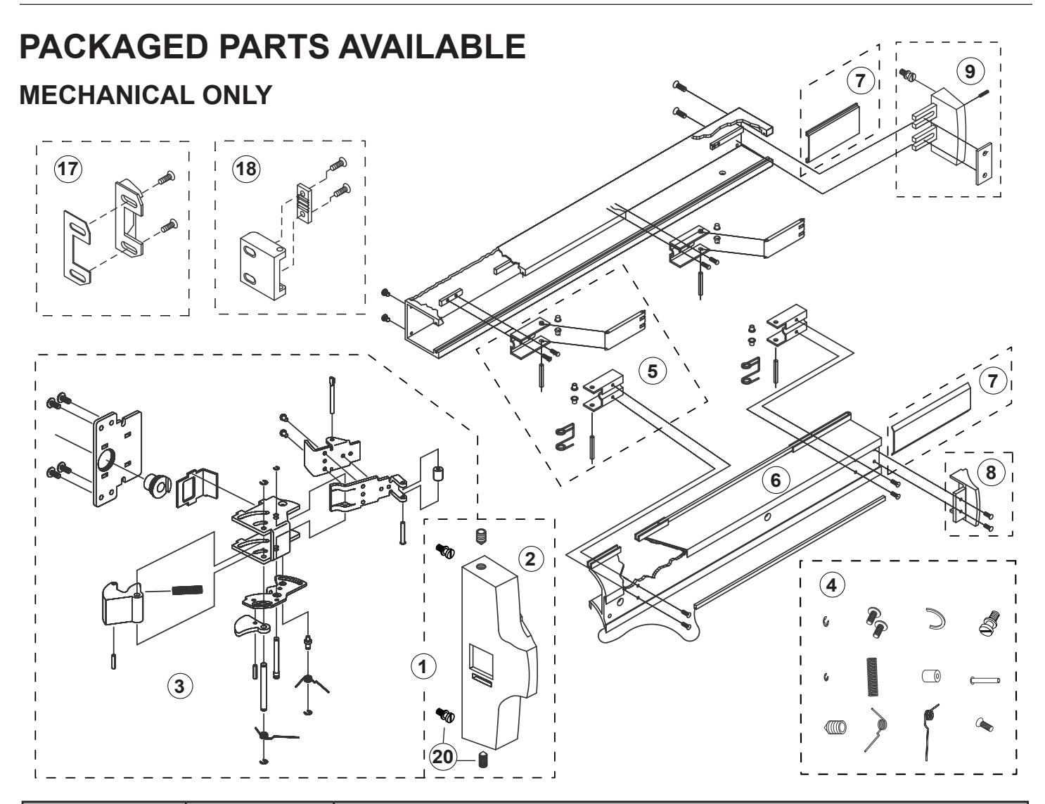
| Assembly No. | Part No. | Description | |
|---|---|---|---|
| 1 | 302622 | Active Head Assembly-Complete | |
| 2 | 302627 | Active Head Cover Package | |
| 3 | 302635 | Active Head Base Plate Assembly | |
| 4 | 302610 | Head Assembly Hardware Package | |
| 5 | 301064 | Control Arm Hardware Package | |
| 6 | 302480PKG | Push-Pad Package | |
| 7 | 301063 | Base Cover Plate Package | |
| 8 | 301265 | Push-Pad End Cap Package | |
| 9 | 301266 | Base End Cap Package | |
| 17 | 302436628 | "C" Type-Surface Mounted Strike | |
| 18 | 302501 | "S" Type-Surface Mounted Strike | |
| 20 | 30SBPKG | Mounting Shoulder Bolt and Set Screw Package (12 Pkg.) | |