Jackson 2095 Rim Panic Device Installation Instructions
Open the original PDF document
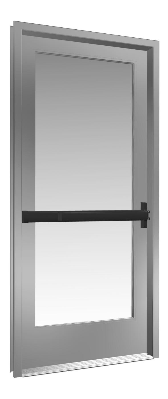
View PDFINSTALLATION INSTRUCTIONS
CRL JACKSON 2095 RIM PANIC EXIT DEVICE

Phone: (800) 421-6144 • Fax: (866) 921-0531 crlaurence.com • usalum.com • crl-arch.com
CRL JACKSON 2095 RIM PANIC EXIT DEVICE
ORDER OF ASSEMBLY AND INSTALLATION
| Parts Identification03 - 04 | |
|---|---|
| Door Preparation 05 | |
| Layout Selection06 - 08 | |
| Door Hardware Installation09 - 12 | |
| Installation of Rim Keyed Cylinder 09 | |
| Installation of Exterior Trim (Optional) 10 | |
| Installation of 2095 Rim Panic Exit Device 11 | |
| Operations Check and Dogging Instructions 12 | |
| Frame Preparation and Strike Installation13 - 14 | |
| Package Parts Available 15 |
TOOLS REQUIRED
Drill Bits: 1/8", 9/32", 5/16", 7/32", Framing Square
5/8", 11/16", 1-3/8" 3/4" Masking Tape
Taps: 1/4-20, 10-32, 8-32 Tape Measure Saw Horses Center Punch Flat Metal File Round Metal File
Cordless Drill Jigsaw with Metal Cutting Blade
Phillips Head Screwdriver Straight Edge
NOTE: Any modifications, other than those specified in this document, could result in this product's failure to meet UL safety ratings and void the manufacturer's warranties.
The rapidly changing technology within the architectural aluminum products industry demands that C.R. Laurence/U.S. Aluminum reserve the right to revise, discontinue, or change any product line, specification, or electronic media without prior written notice.
NOTE: Dimensions in parentheses ( ) are millimeters unless otherwise noted.
PARTS IDENTIFICATION
| FASTENERS PROVIDED USED WITH | ||||||
|---|---|---|---|---|---|---|
|
CALL
OUT |
QTY. | FASTENER |
FASTENER
DESCRIPTION |
PART |
PART NUMBER
AND DESCRIPTION |
|
| A | 2 |
1/4"-20 x 1/4"
Shoulder Stud Screws |
302622 Active
Head Assembly 302627 Active Head Cover Package |
|||
| A | 1 |
1/4"-20 x 1/4"
Shoulder Stud Screw |
301266
Base End Cap Package |
|||
| B | 2 |
1/4"-20 x 5/16"
Set Screw |
302622 Active
Head Assembly 302627 Active Head Cover Package |
|||
| B | 1 |
1/4"-20 x 5/16"
Set Screw |
301266
Base End Cap Package |
|||
| © | 2 |
#10-32 x 5/8" Oval Head
Machine Screw |
302436 "C" Type
Surface Mounted Strike |
|||
| (D) | 2 |
#10-24 x 5/8" or 1-1/4" Oval
Head Machine Screw |
302501 "S" Type
Surface Mounted Strike |
|||
| E | 2 |
1/4"-20 x 1-3/4"
Breakaway Screws |
DL911 Rim Keyed Cylinder | |||
| F | 2 | #10-32 x 2-1/8" FHMS |
9500LV01 or 9500LV02
Optional Exterior Trim with Lever Assembly |
|||
PARTS IDENTIFICATION
| PARTS LIST | ||||
|---|---|---|---|---|
|
CALL
OUT |
PART | PART NO. | DESCRIPTION | |
| G | DL911 | Optional Rim Cylinder | ||
| H | 302436 |
"C" Type Surface
Mounted Strike |
||
| I | 302501 |
"S" Type Surface
Mounted Strike |
||
| J | 302521 |
Wood Door
Mounting Kit |
||
| K | 302671 |
Cylinder Dogging
Hardware Kit |
||
DOOR PREPARATION
REMOVE DOOR AND PREPARE PER TEMPLATES
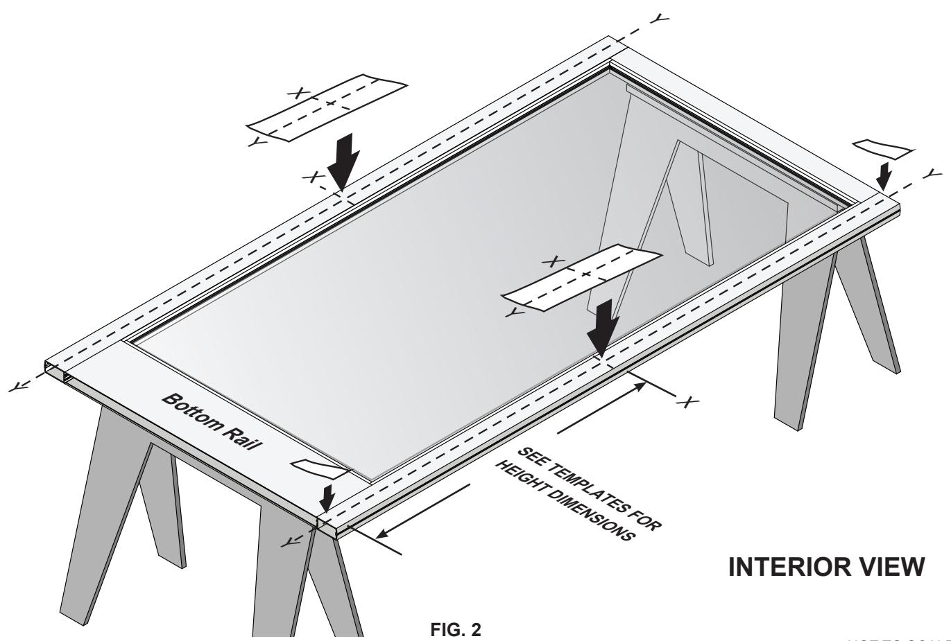
- 1. Place the door horizontally on the stands interior side up.
- 2. Mark the stile centerlines 1-1/8" (28.6) from the inside edge of the stile. (Fig. 1)
- 3. Mark the corresponding layouts on to the stile using the vertical centerlines at the specified height. (Fig. 2)
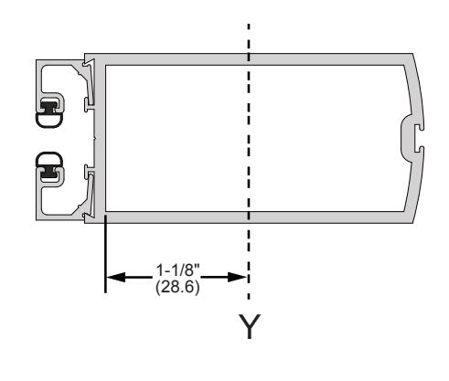
FIG. 1
NOT TO SCALE
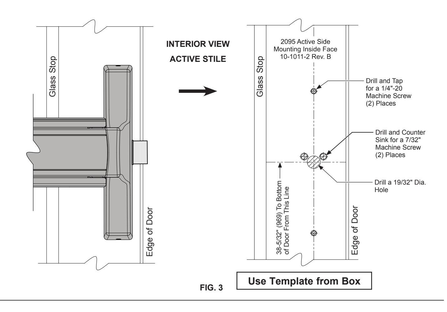
DOOR PREPARATION – LAYOUT SELECTION
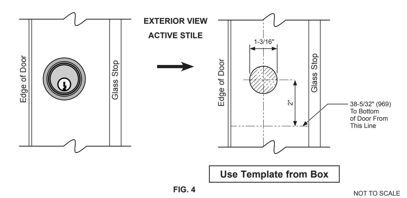
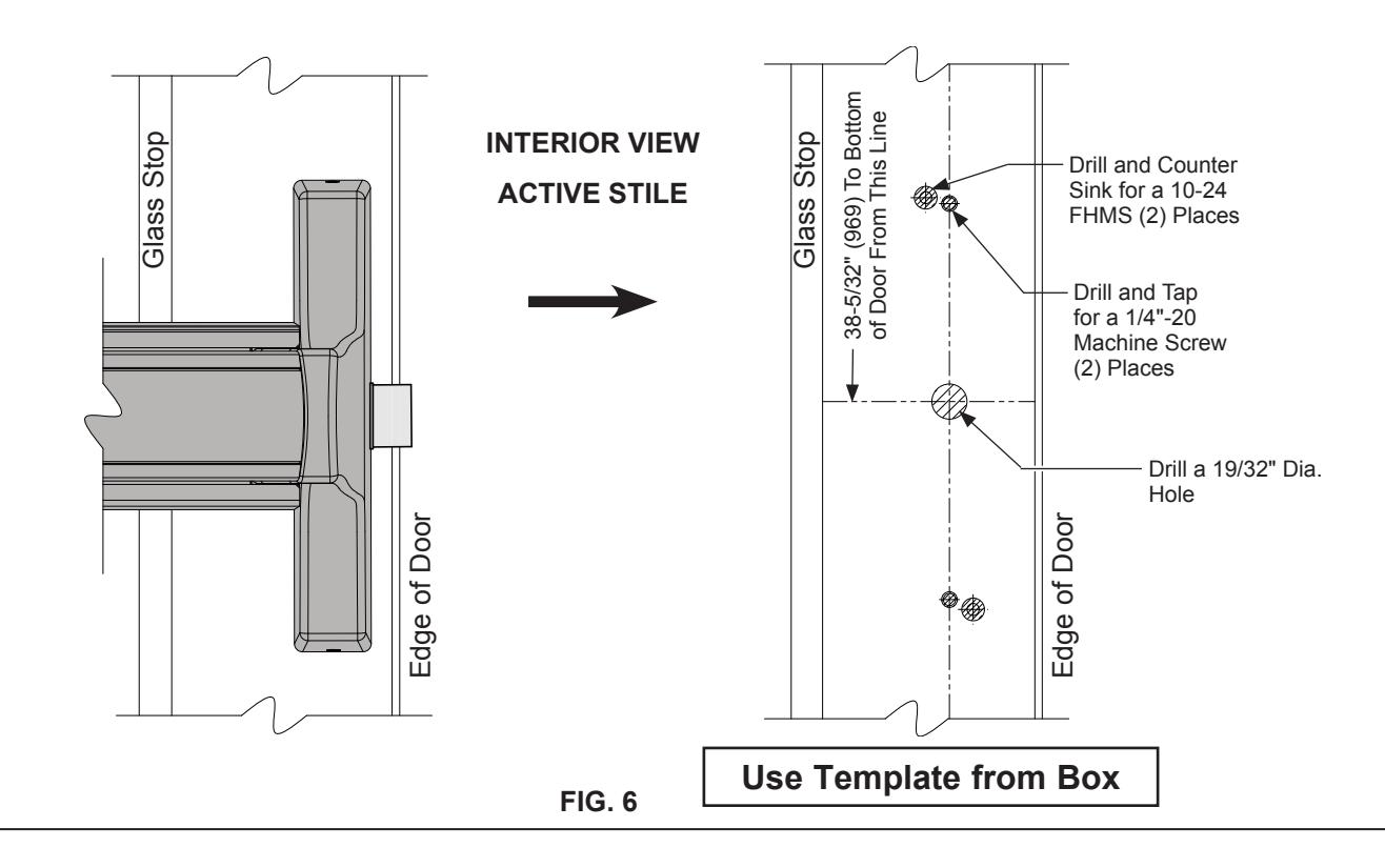
2095 PANIC EXIT DEVICE INSTALLATION - ACTIVE STILE
DOOR PREPARATION – LAYOUT SELECTION
2095 PANIC EXIT DEVICE INSTALLATION - INACTIVE STILE
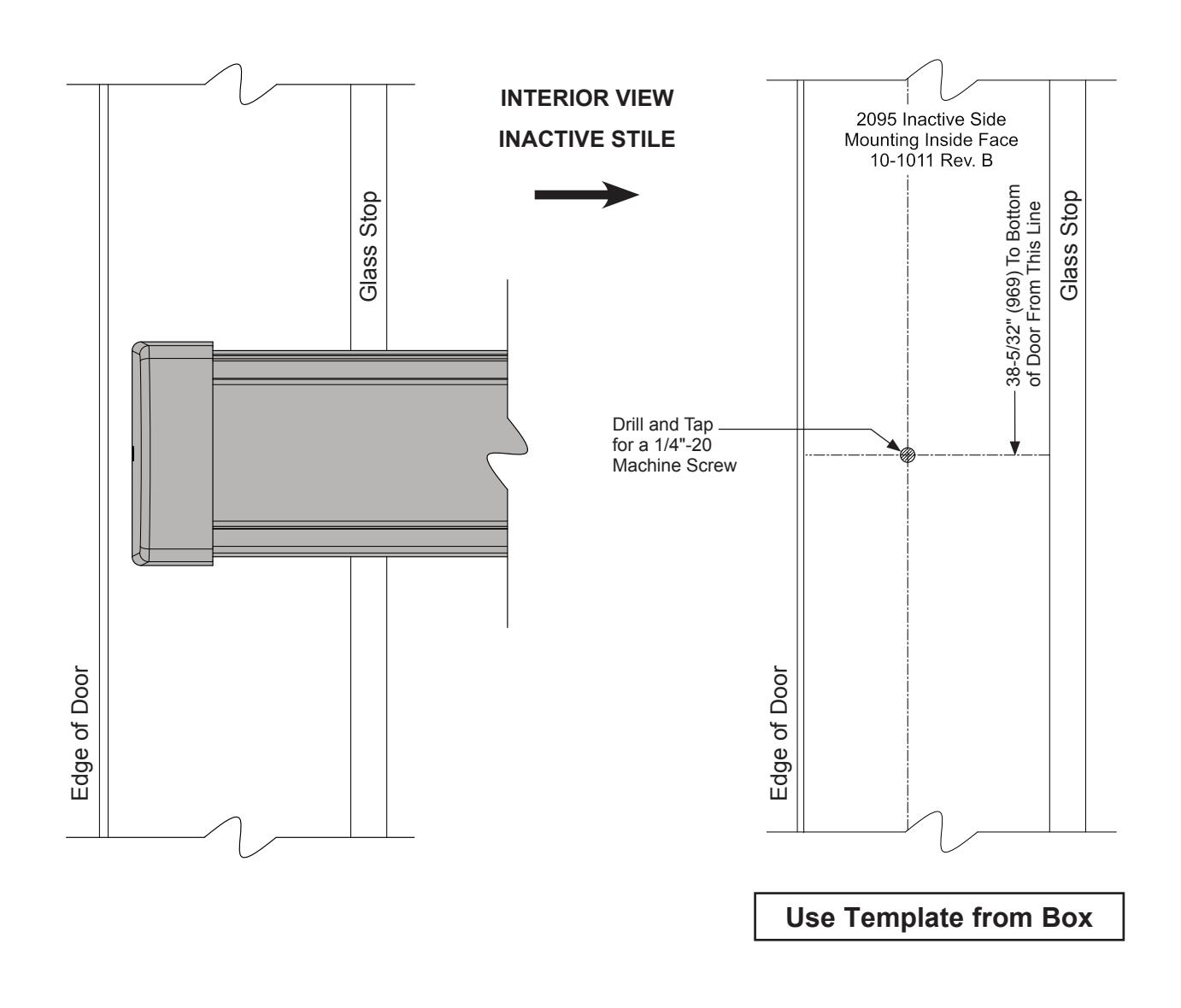
FIG. 5
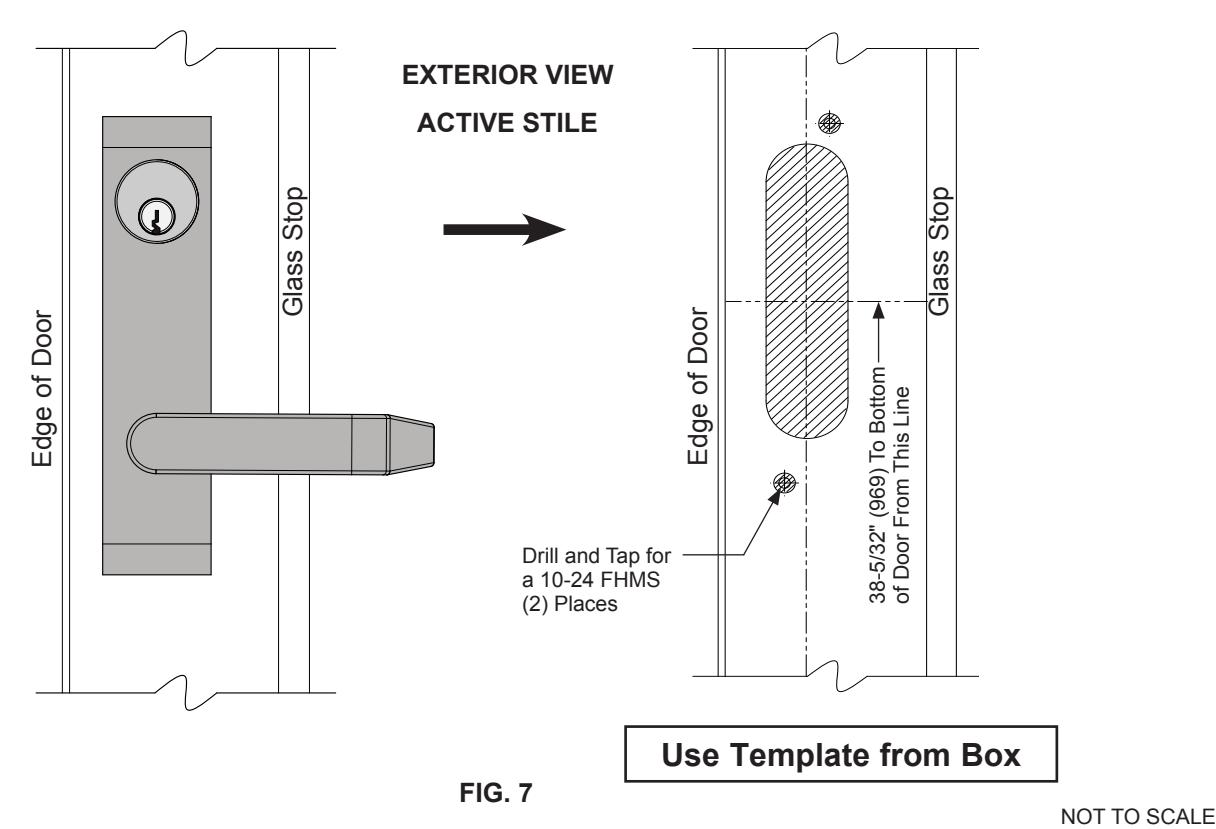
DOOR PREPARATION – LAYOUT SELECTION
2095 PANIC EXIT DEVICE WITH EXTERIOR LEVER TRIM
DOOR HARDWARE INSTALLATION
INSTALLATION OF RIM KEYED CYLINDER
- 1. Insert the rim keyed cylinder assembly into the active stile and fasten with (2) 1/4"-20 x 1-1/4" breakaway screws (Fig. 8) . E
- 2. Attach the (2) 1/4"-20 x 1/4" shoulder stud screws to the active stile. (Fig. 8) A
- 3. Attach (1) 1/4"-20 x 1/4" shoulder stud screw on the Inactive Stile. (Fig. 8) A
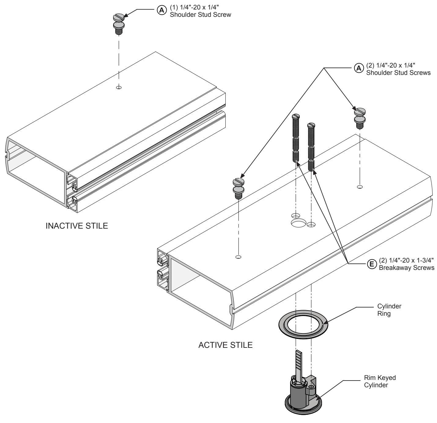
NOT TO SCALE FIG. 8
DOOR HARDWARE INSTALLATION (CONTINUED)
INSTALLATION OF EXTERIOR LEVER TRIM (OPTIONAL)
NOTE: Exterior trim must be installed before attaching exit device.
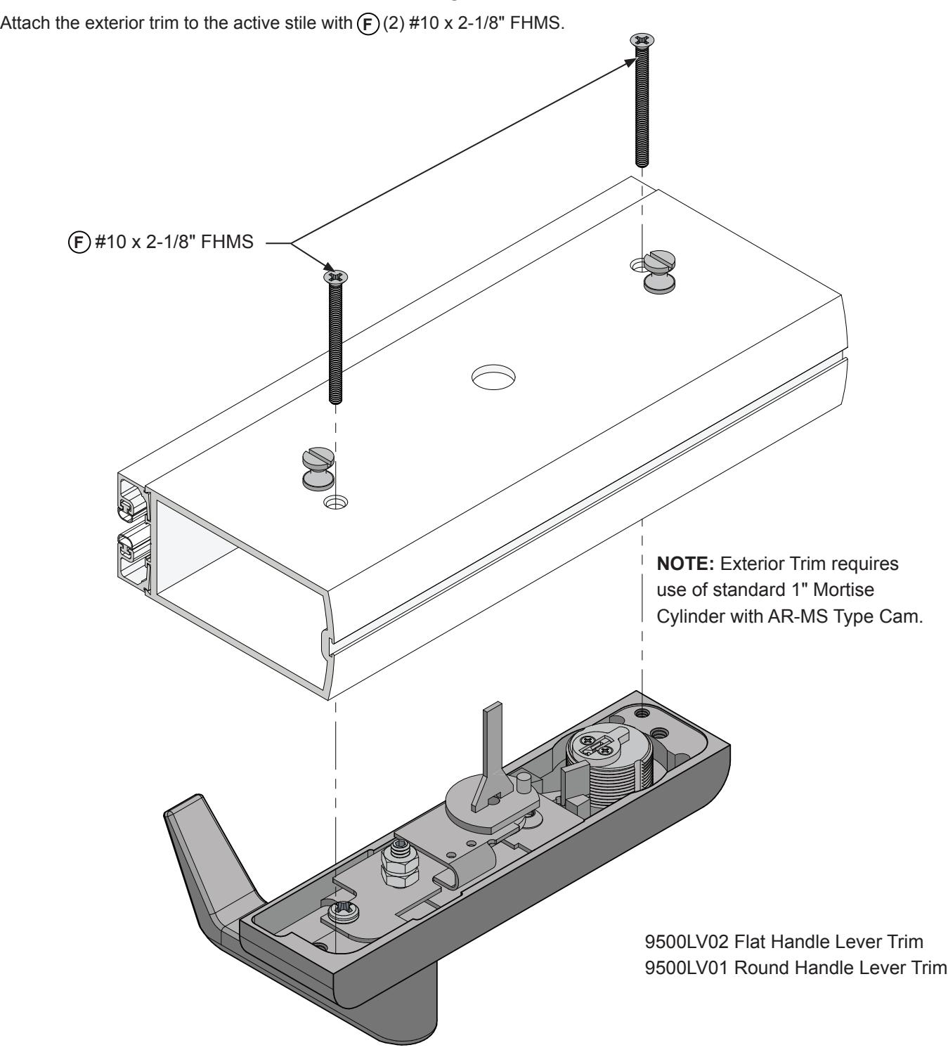
FIG. 9
DOOR HARDWARE INSTALLATION (CONTINUED)
INSTALLATION OF 2095 RIM PANIC EXIT DEVICE
- 1. Install the exit device on the door stiles.
- 2. Tighten the (B) (2) set screws and (B) (1) set screw on each side of the door stiles. (Fig. 10)
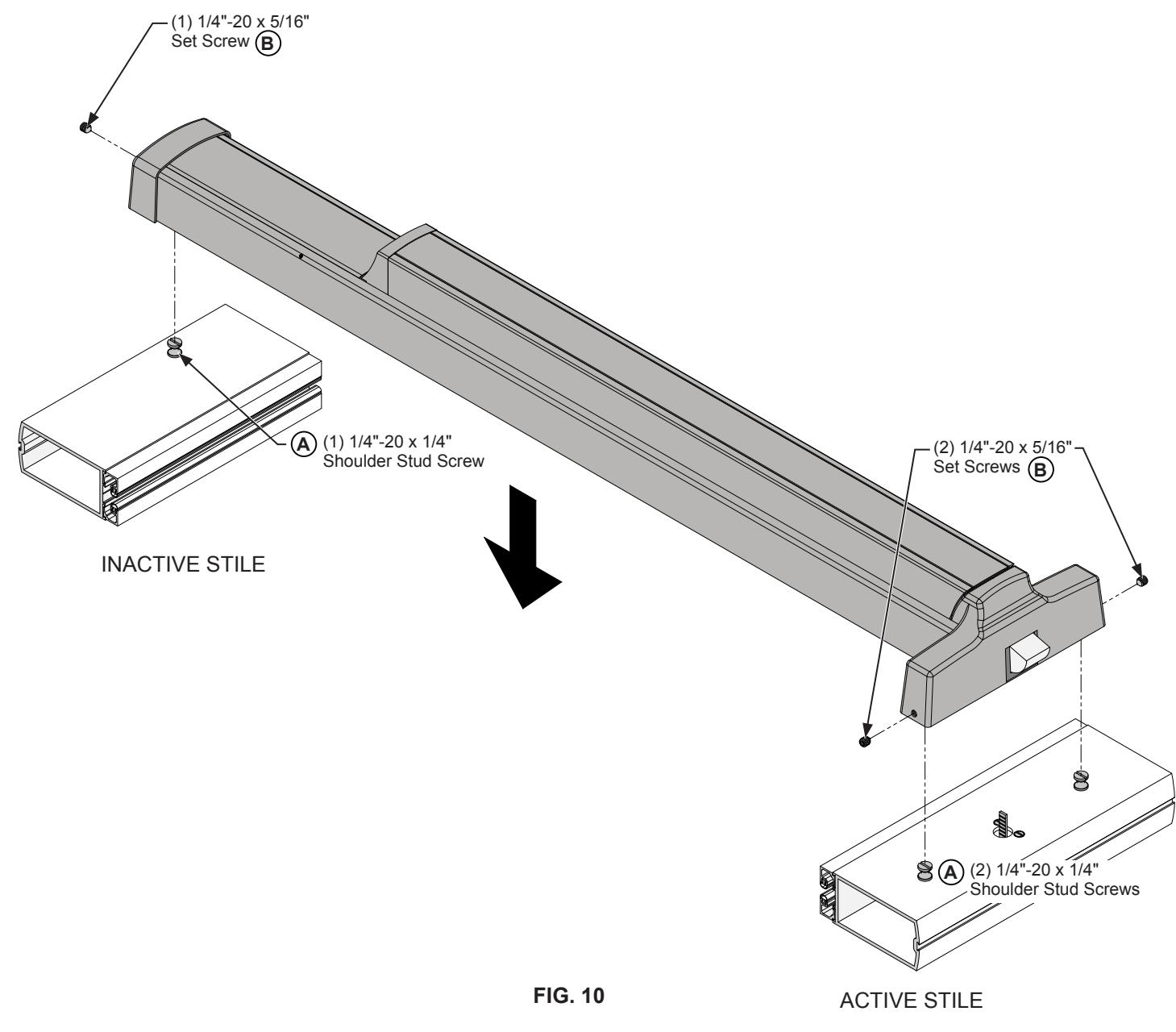
NOT TO SCALE
DOOR HARDWARE INSTALLATION (CONTINUED)
OPERATIONS CHECK AND DOGGING INSTRUCTIONS
OPERATIONS CHECK:
Depress the push bar to assure free movement of the latch.
DOGGING INSTRUCTIONS:
TO DOG Fully depress and hold the Touch Bar, push the Dogging Pin In and Release the Touch Bar. (Fig. 11)
TO UNDOG Push Dogging Pin In, Touch Bar will release.
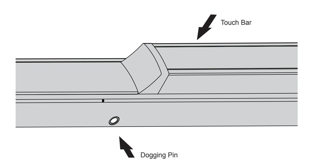
FIG. 11
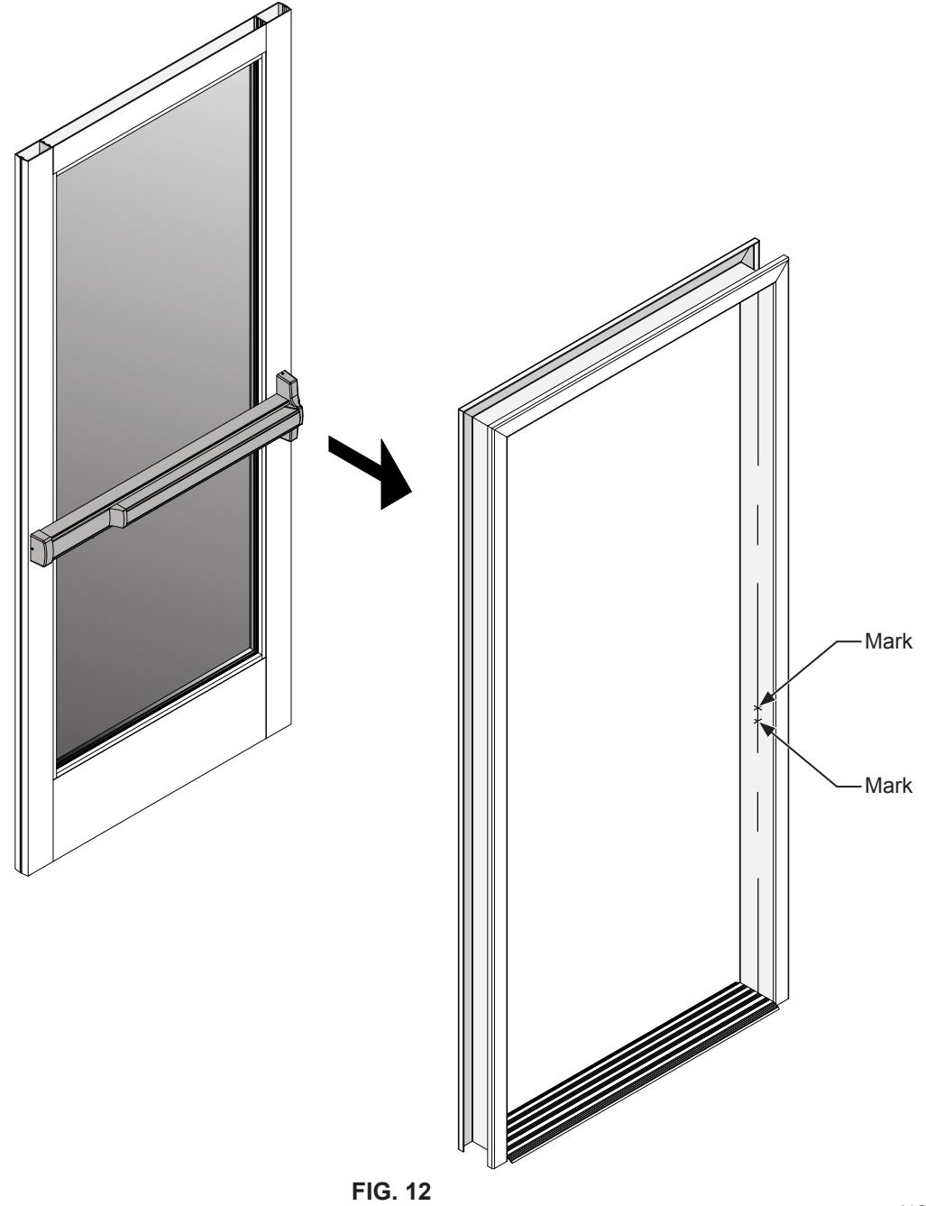
FRAME PREPARATION
RE-ATTACH DOOR TO FRAME
- 1. Make sure that the panic exit device is in the dogged position. See page 12 for dogging instructions.
- 2. With the door in place and in the closed position, mark the center line locations on the door frame. (Fig. 12)
- 3. Finish the frame preparation using the layout drawing on page 14.
NOT TO SCALE
FRAME PREPARATION (CONTINUED)
ATTACH THE STRIKE
Drill and tap for (2) 10-32 x 5/8" Oval HD MS on the mark made in step 2 of the frame preparation on page 13. Attach the strike to the door jamb using (2) 10-32 x 5/8" Oval HD MS. C (Fig. 13) C
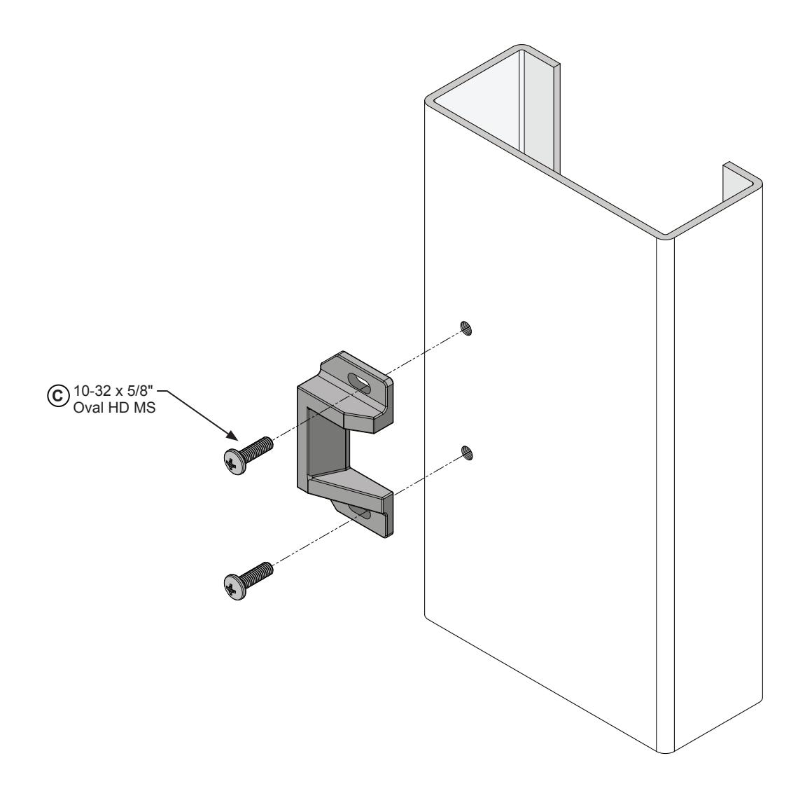
FIG. 13
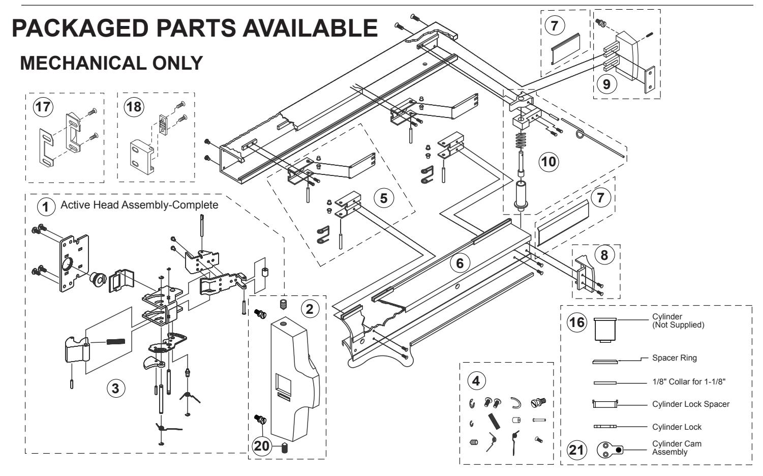
| Assembly No. | Part No. | Description | |
|---|---|---|---|
| 1 | 302622 | Active Head Assembly-Complete | |
| 2 | 302627 | Active Head Cover Package | |
| 3 | 302635 | Active Head Base Plate Assembly | |
| 4 | 302610 | Head Assembly Hardware Package | |
| 5 | 301064 | Control Arm Hardware Package | |
| 6 | 302480PKG | Push-Pad Package | |
| 7 | 301063 | Base Cover Plate Package | |
| 8 | 301265 | Push-Pad End Cap Package | |
| 9 | 301266 | Base End Cap Package | |
| 10 | 302467 | LHRB-Dogging Assembly | |
| Not Shown | 302462 | RHRB-Dogging Assembly | |
| 16 | 302671 | Cylinder Dogging Hardware Package | |
| 17 | 302436628 | "C" Type-Surface Mounted Strike | |
| 18 | 302501 | "S" Type-Surface Mounted Strike | |
| 20 | 30SBPKG | Mounting Shoulder Bolt and Set Screw Package (12 Pkg.) | |
| 21 | 302572 | Cylinder Dogging Cam | |