Jackson 2086 CVR Panic Device Installation Instructions
Open the original PDF document
View PDFINSTALLATION INSTRUCTIONS
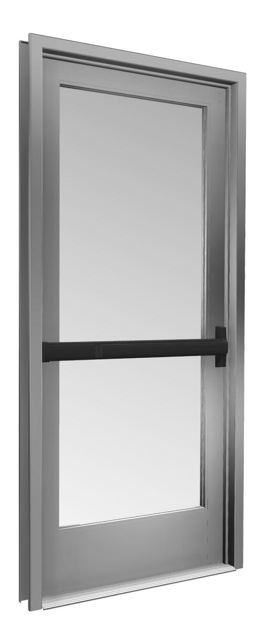
CRL JACKSON 2086 CONCEALED VERTICAL ROD PANIC EXIT DEVICE

Phone: (800) 421-6144 • Fax: (866) 921-0531 crlaurence.com • usalum.com • crl-arch.com
ORDER OF ASSEMBLY AND INSTALLATION
| PARTS IDENTIFICATION | 03 - 04 |
|---|---|
| DOOR PREPARATION | 05 |
| LAYOUT SELECTION | 06 - 09 |
| HARDWARE INSTALLATION | 10 - 14 |
| INSERT ROD AND CASE | |
| INSTALL MORTISE CYLINDER LOCK AND MOUNTING PAD (OPTIONAL) | 11 |
| INSTALL EXTERIOR LOCKING LEVER TRIM (OPTIONAL) | 12 |
| INSTALL 2086 EXIT DEVICE | 13 |
| OPERATIONS CHECK AND DOGGING INSTRUCTIONS | 14 |
| FRAME PREPARATION AND STRIKE INSTALLATION | 15 - 16 |
| DOOR HARDWARE ADJUSTMENTS - UPPER AND BOTTOM BOLT | |
| PACKAGE PARTS AVAILABLE | 18 |
TOOLS REQUIRED
Drill Bits: 1/8", 9/32", 5/16", 7/32", 5/8", 11/16", 1-3/8" Taps: 1/4-20, 10-32, 8-32 Tape Measure Saw Horses Cordless Drill Framing Square Masking Tape Center Punch Flat Metal File Round Metal File Jigsaw with Metal Cutting Blade
Phillips Head Screw Driver Straight Edge
NOTE: Any modifications, other than those specified in this document, could result in this product's failure to meet UL safety ratings and void the manufacturer's warranties.
The rapidly changing technology within the architectural aluminum products industry demands that U.S. Aluminum reserve the right to revise, discontinue or change any product line, specification or electronic media without prior written notice.
NOTE: Dimensions in parentheses ( ) are millimeters unless otherwise noted.
CRL US ALUMINUM
PARTS IDENTIFICATION
| FASTENERS PROVIDED USED WITH | USED WITH | ||||
|---|---|---|---|---|---|
| CALL | QTY. | FASTENER |
FASTENER
DESCRIPTION |
PART |
PART NUMBER
AND DESCRIPTION |
| A | 2 |
1/4"-20 x 1/4"
Shoulder Stud Screws |
302617 and 302619
Active Head Assembly |
||
| A | 1 |
1/4"-20 x 1/4"
Shoulder Stud Screw |
301266 Base End
Cap Package |
||
| B | 2 |
1/4"-20 x 5/16"
Set Screw |
302617 and 302619
Active Head Assembly |
||
| B | 1 |
1/4"-20 x 5/16"
Set Screw |
• |
301266
Base End Cap Package |
|
| © | 4 |
#10 x 1/2" FH
Self Tapping Screw |
30934 Top Bolt Guide
30320 Bottom Bolt Guide Assembly |
||
| D | 2 |
#10-32 x 3/4" FH
Machine Screw |
30824
Trip Bracket Package |
||
| E | 1 |
1/4"-20 x 1"
Adjustment SScrew |
30824
Trip Bracket Package |
||
| F | 4 |
#10-32 x 3/8" FH
Machine Screw |
301084 Top and Bottom
Strike Package |
||
| G | 2 |
#8-32 x 2" FH
Machine Screw |
30821J
Optional Mortise Cylinder Mounting Pad |
||
| H | 2 |
#10-32 x 2-1/8"
FHMS |
8500LV01 and 8500LV02
Optional Exterior Trim with Lever Assembly |
||
PARTS IDENTIFICATION
| PARTS LIST | |||||
|---|---|---|---|---|---|
|
CALL
OUT |
PART | PART NO. | DESCRIPTION | ||
| I | DL2170 |
Optional 1" Single
Mortise Cylinder |
|||
| J | 30799 |
Actuator Link included in 2086
Active Head Assembly Hardware Package 302607 |
|||
| K | 30915J | Rod and Case Assembly - 7/0 | |||
| L | 30PBAW |
Bolt Guide
Adjustment Wrench |
|||
| M |
301347
301348 |
Optional 12" and 24"
Top Rod Extender |
|||
| N | 301552PKG | Rod Silencers (12 Pkg.) | |||
DOOR PREPARATION
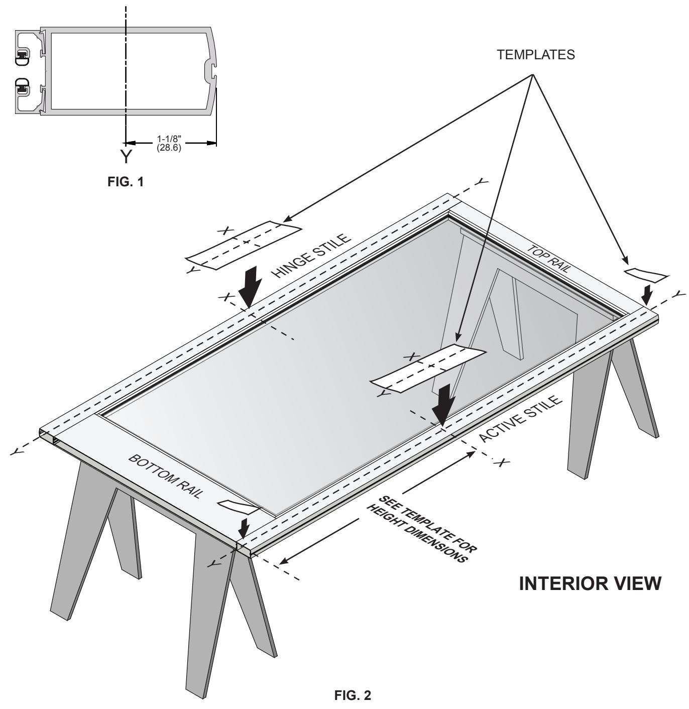
REMOVE DOOR AND PREPARE PER TEMPLATE
- 1. Place the door horizontally on the stands interior side up.
- 2. Mark the stile centerlines 1-1/8" (28.6) from the inside edge. ( Fig. 1)
- 3. Mark the corresponding layouts on to the stile using the vertical centerlines at the specified height. ( Fig. 2)
NOT TO SCALE
05
DOOR PREPARATION - LAYOUT SELECTION
2086 EXIT DEVICE INSTALLATION - ACTIVE STILE
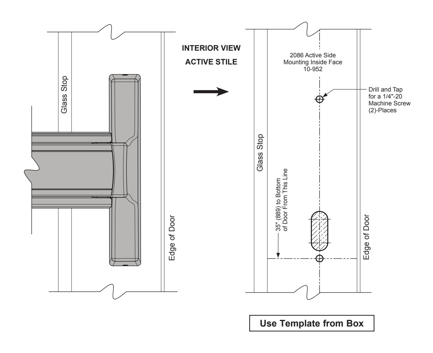
FIG. 3
NOT TO SCALE
DOOR PREPARATION – LAYOUT SELECTION
2086 EXIT DEVICE INSTALLATION - INACTIVE STILE
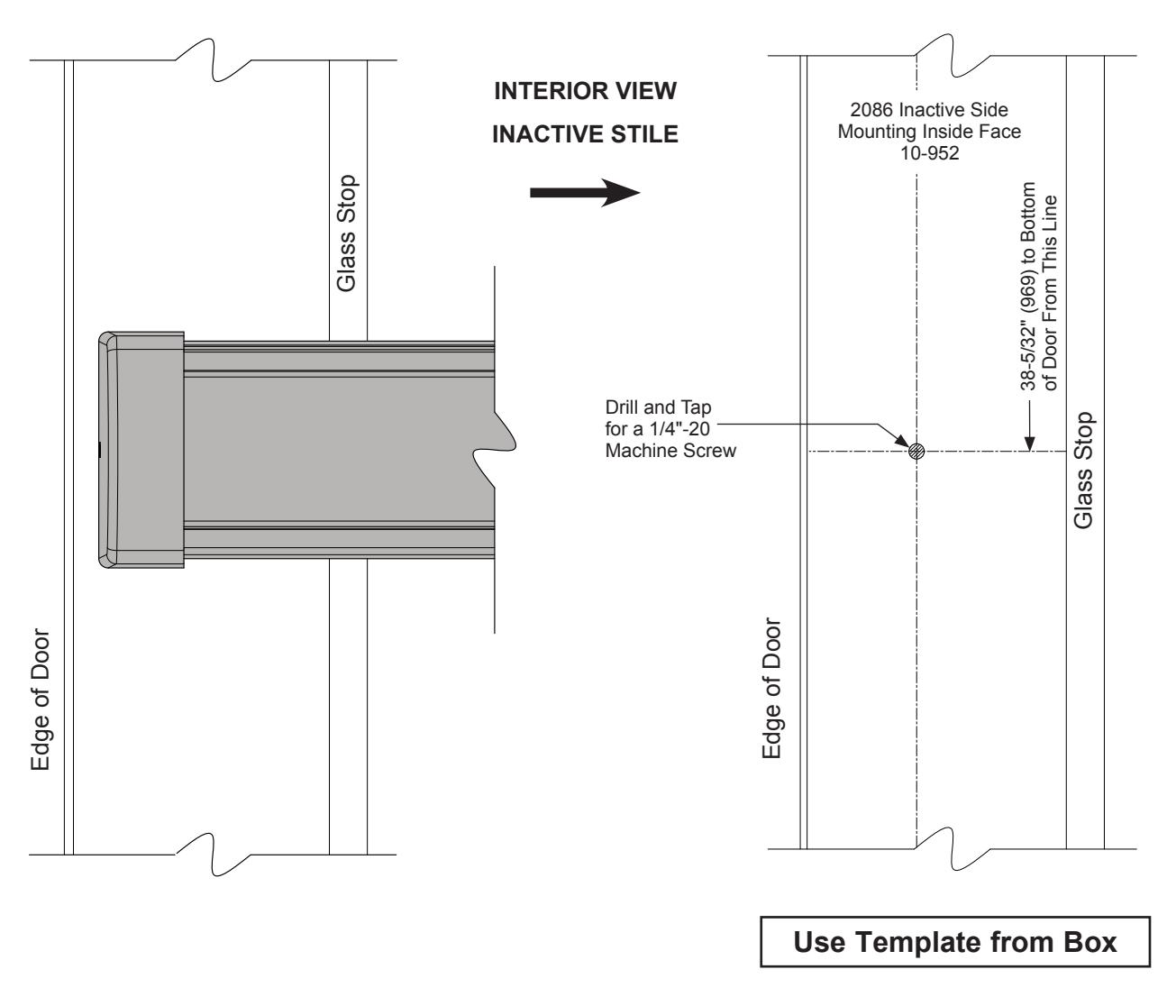
FIG. 4
NOT TO SCALE
07
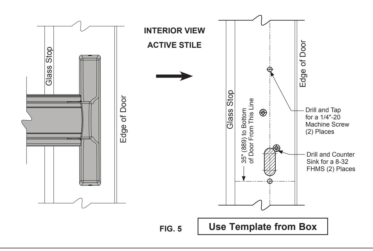
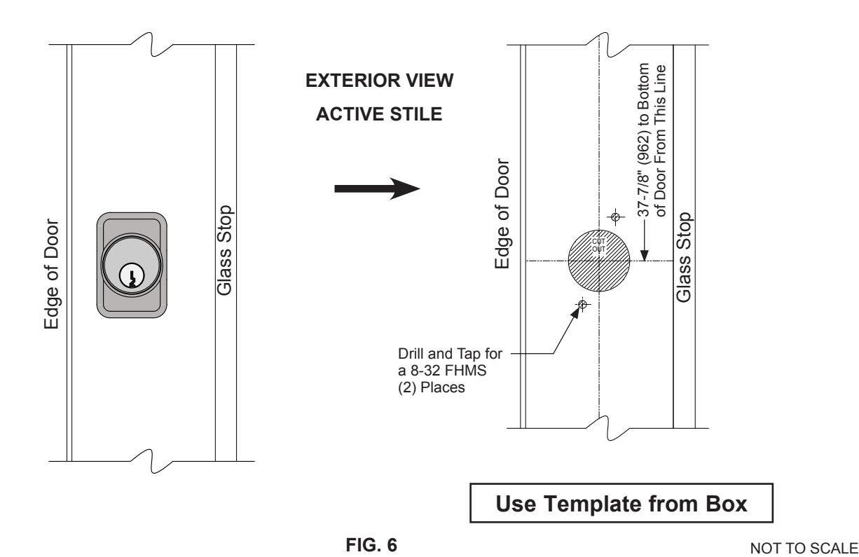
DOOR PREPARATION – LAYOUT SELECTION
2086 EXIT DEVICE INSTALLATION WITH LOCK CYLINDER AND MOUNTING PAD
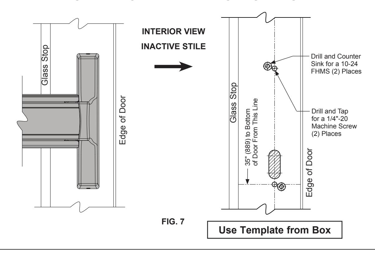
DOOR PREPARATION – LAYOUT SELECTION
2086 EXIT DEVICE INSTALLATION WITH EXTERIOR LOCKING LEVER TRIM
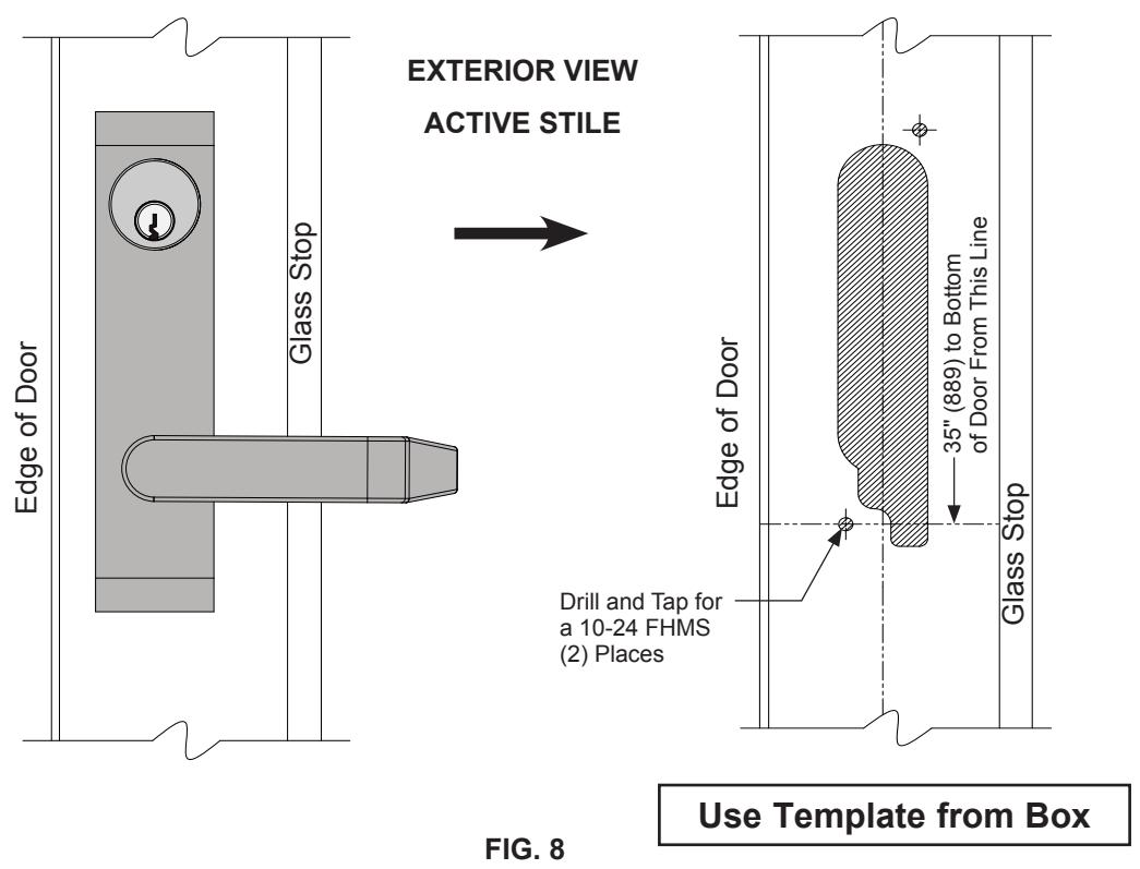
NOT TO SCALE
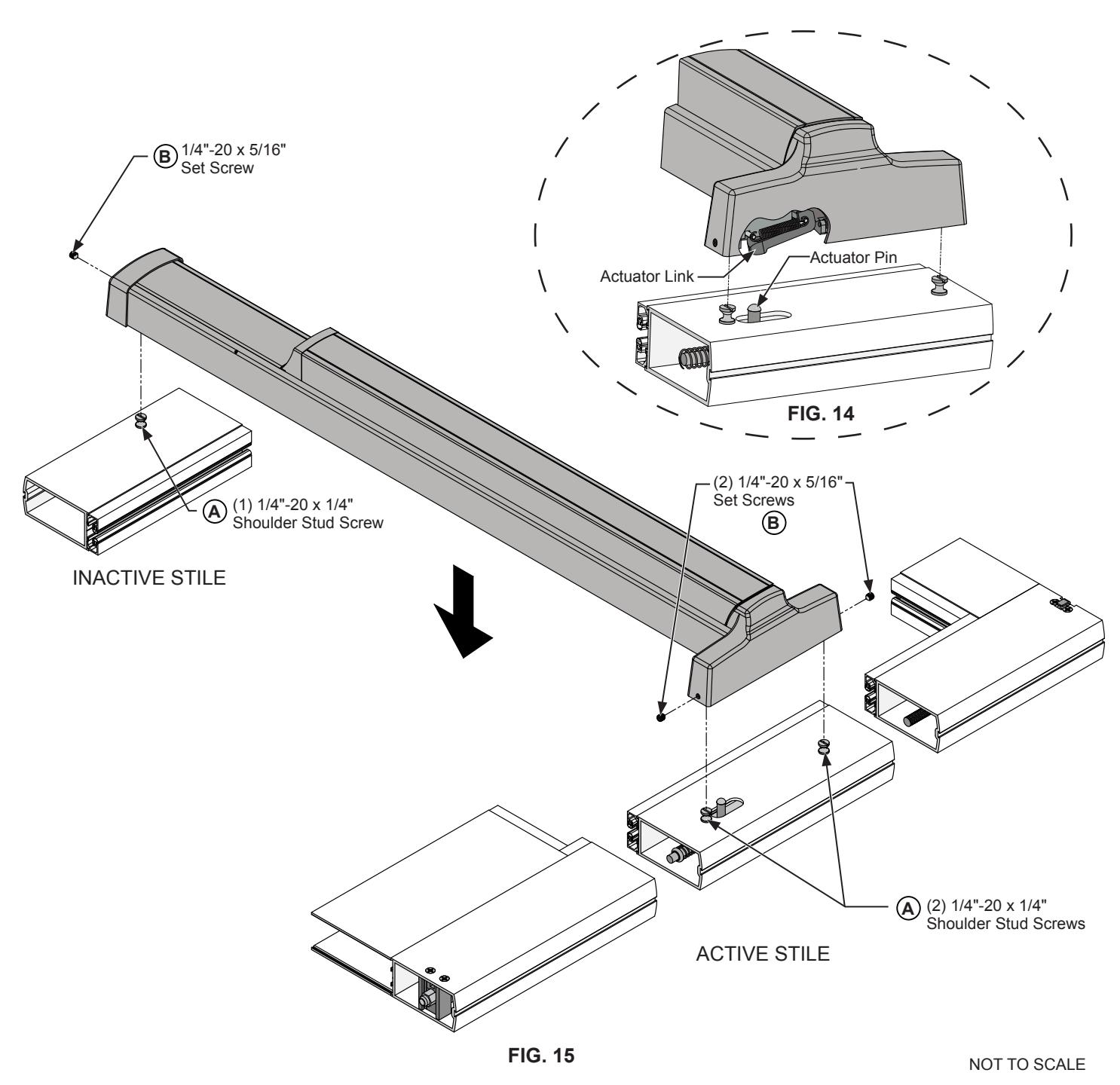
DOOR HARDWARE INSTALLATION (CONTINUED) INSERT ROD AND CASE
- Insert the panic device rod and case assembly into active stile (Fig. 9).
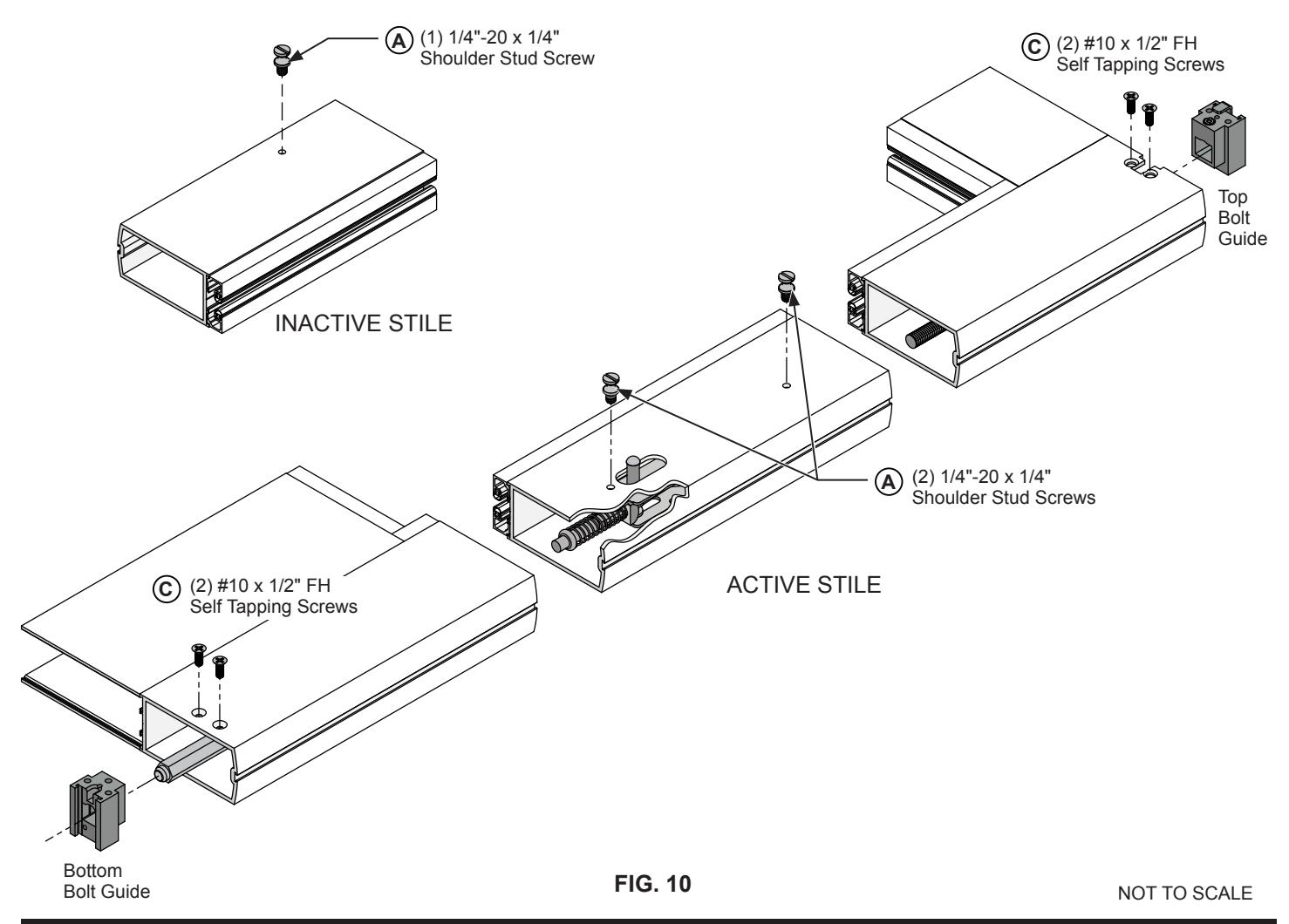
- 2. Align actuator pin through the slotted cut-out on interior face of stile, fastening with (A) (2) 1/4"-20 x 1/4" shoulder stud screws. (Fig. 10)
- Adjust the bottom and top bolts, to extend 1/2" past the top and bottom stiles.
- 4. Install the top bolt guide assembly using © (2) #10 x 1/2" FH self threading screws at the top of the active door stile. The (2) holes face the interior side.
- 5. Install the bottom bolt guide assembly using © (2) #10 x 1/2" FH self threading screws at the bottom of the active door stile. The (2) holes face the interior side of stile.
- 6. Attach (A) (1) 1/4"-20 x 1/4" shoulder stud screw on the Inactive Stile. (Fig. 10)
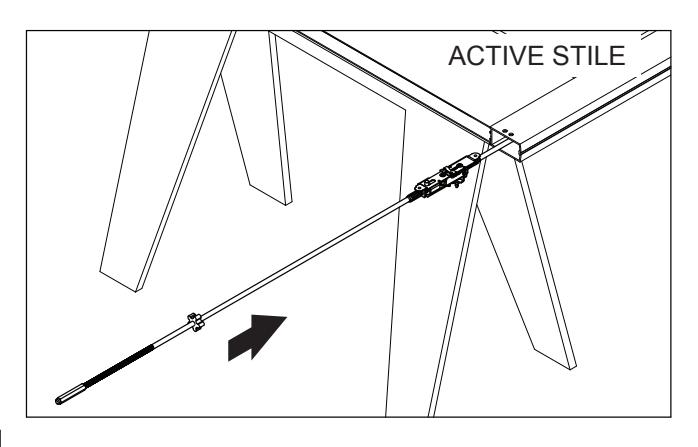
FIG. 9
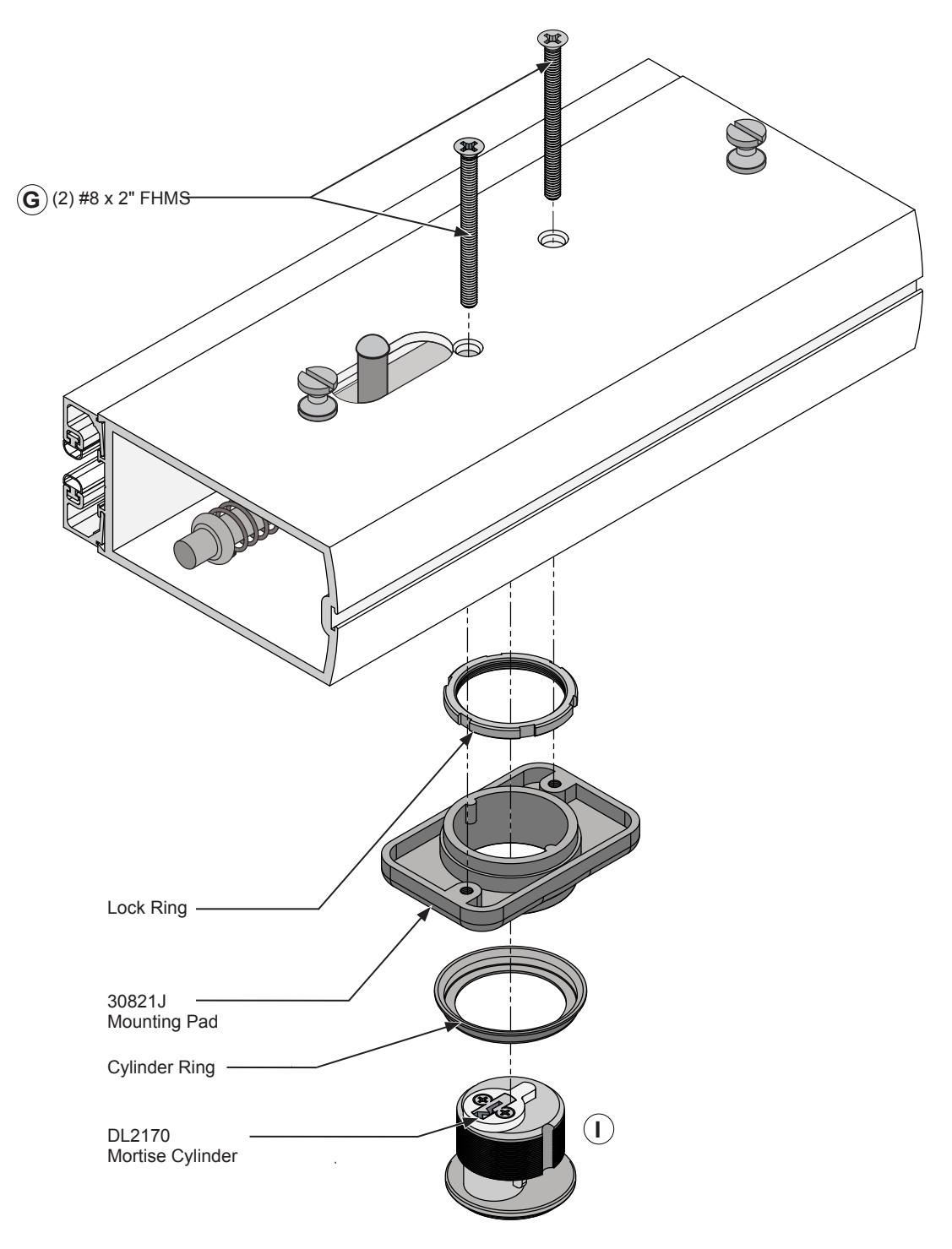
INSTALL OPTIONAL MORTISE CYLINDER LOCK AND MOUNTING PAD DOOR HARDWARE INSTALLATION (CONTINUED)
NOTE: Lock and Mounting Pad must be installed before attaching exit device.
1. Attach the Mortise Cylinder Lock to the Mounting Pad and secure it with the Lock Ring, using (2) #8 x 2" Flat head screws provided. F
NOT TO SCALE FIG. 12
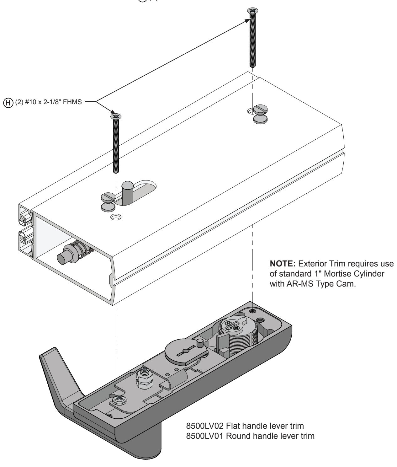
INSTALL OPTIONAL LOCKING LEVER EXTERIOR TRIM DOOR HARDWARE INSTALLATION (CONTINUED)
NOTE: Exterior trim must be installed before attaching exit device.
1. Attach the exterior trim to the active stile with (2) #10 x 2-1/8" FHMS H
NOT TO SCALE FIG. 13
DOOR HARDWARE INSTALLATION (CONTINUED)
INSTALL 2086 EXIT DEVICE
- 1. Install the exit device on the door stiles assuring the actuator link engages the actuator pin. (Fig. 14)
- 2. Tighten (3) set screws on each side of the door stiles. B (Fig. 15)
DOOR HARDWARE INSTALLATION (CONTINUED)
OPERATIONS CHECK AND DOGGING INSTRUCTIONS OPERATIONS CHECK:
- 1. Depress the push bar to assure free movement of the rod and case assembly. Both upper and bottom bolts should activate to the open position. The upper bolt should drop into the open position (Fig. 22).
- 2. The bottom bolt should fully retract. If the bolts fail to operate as described, review the actuator link and actuator pin and make sure the actuator link engages the actuator pin (Fig. 14).
DOGGING INSTRUCTIONS:
TO DOG Fully depress and hold the Touch Bar, push the Dogging Pin in and release the Touch Bar (Fig. 16).
TO UNDOG Push Dogging Pin in, Touch Bar will release.
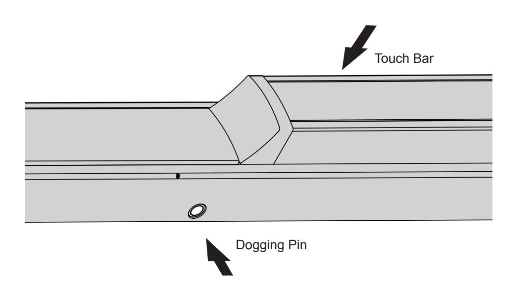
FIG. 16
NOT TO SCALE
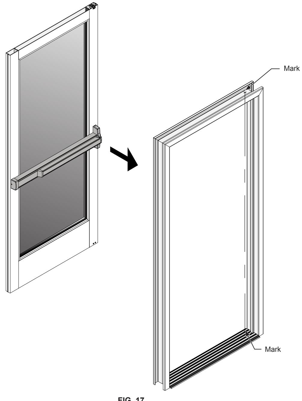
FRAME PREPARATION
RE-ATTACH DOOR TO FRAME
- 1. Make sure that the panic exit device is in the dogged position. Both the upper and bottom latches must clear the frame. Re-attach the door to the frame (Fig. 17).
- 2. With the door in place and in the closed position, mark the center line locations on the header and threshold of both the upper and bottom latches.
- 3. Finish the header and threshold preparation using the layout drawings on page 17.
NOT TO SCALE FIG. 17
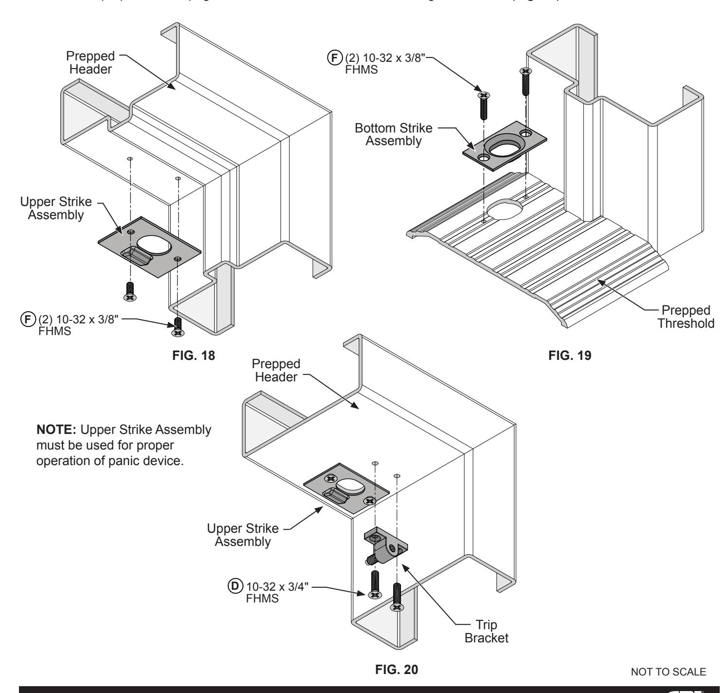
FRAME PREPARATION (CONTINUED)
ATTACH UPPER STRIKE
1. Drill and tap for F (2) 10-32 x 3/8" FHMS on the mark made in step 2 of the frame preparation on page 16. Attach the upper strike to header using F (2) 10-32 x 3/8" FHMS (Fig. 18). If the header does not have a door stop attach the trip bracket provided to the header using D (2) 10-32 x 3/4" FHMS (Fig. 20).
ATTACH BOTTOM STRIKE
1. Cut out a 1" long x 13/16 wide hole and Drill and tap for F (2) 10-32 x 3/8" FHMS on the mark made in step 2 of the frame preparation on page 16. Attach the bottom strike centering on the mark (Fig. 19).
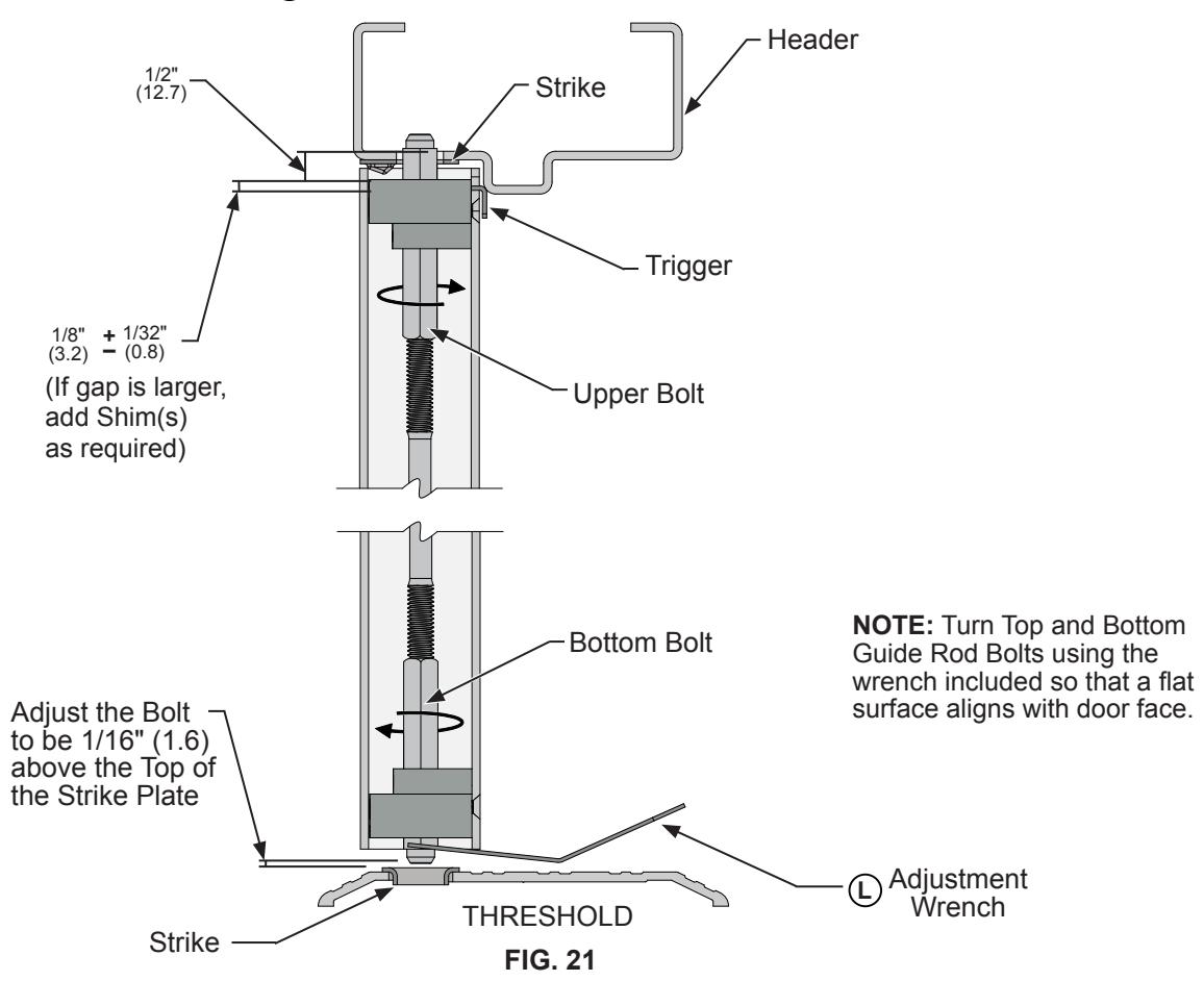
DOOR HARDWARE ADJUSTMENTS
UPPER BOLT:
- 1. The door must be in the closed position and the push bar must be in the un-dogged position to complete the following adjustments.
- 2. Depress the push bar, The bottom and upper rods will retract. With the rods in this position adjust the bottom bolt using the adjustment wrench (L) included. Adjust the upper bolt 1/16" to 1/8" (1.6 to 3.2) gap from the header. When the panic is in the released position the upper rod will extend 1/2" (12.7) into the header as shown in (Fig. 21).
BOTTOM BOLT:
- 1. The door must be in the closed position and the push bar must be in the un-dogged position to complete the following adjustments.
- Depress the push bar, The bottom and upper rods will retract. With the rods in this position adjust the bottom bolt using the adjustment wrench (L) included as shown in (Fig. 21).
MANUAL CHECK:
Release the dogging mechanism. The rods will then extend into the locked position.
OPERATIONS CHECK:
Depress the push bar. The bottom bolt should retract to the bottom edge of the door stile. The upper bolt will return to the open position.

** Important: If the upper bolt returns to the open position with the push bar being partially depressed, or if the upper bolt does not go to the open position when the push bar is fully depressed repeat the dogging procedure and the adjustment steps on page 18. The upper and lower bolts might need to be adjusted again (Fig. 21).
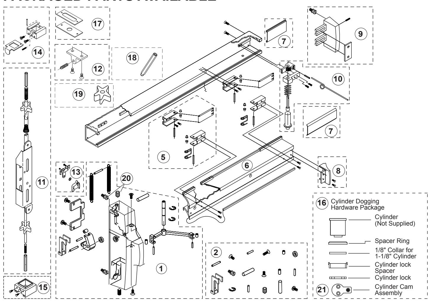
PACKAGED PARTS AVAILABLE
|
Assem.
No. |
Part No. | Description |
Assem.
No. |
Part No. | Description |
|---|---|---|---|---|---|
| 1 | 302617 | LHRB - Active Head Assembly | 13 | 30916 | Rod and Case Hardware Package |
| Not shown | 302619 | RHRB - Active Head Assembly | 14 | 30934 | Top Bolt Guide Assembly |
| 2 | 302607 | Head Assembly Hardware Package | 15 | 30320 | Bottom Bolt Guide Assembly |
| 5 | 301064 | Control Arm Hardware Package | 16 | 302671 | Cylinder Dogging Package |
| 6 | 302480PKG | Push-Pad Package | 17 | 301084 | Strike Package - Top and Bottom |
| 7 | 301063 | Base Cover Plate Package | 18 | 30763P | Top and Bottom Bolts (1 Ea.) |
| 8 | 301265 | Push-Pad End Cap Package | 19 | 301552PKG | Rod Silencers (12 Pkg.) |
| 9 | 301266 | Base End Cap Package | 20 | 30SBPKG | Mounting Shoulder Bolt and Set Screw Pkg. (12 Ea.) |
| 10 | 302467 | LHRB - Dogging Assembly | 21 | 302572 | Cylinder Dogging Cam |
| Not shown | 302462 | RHRB - Dogging Assembly | Not shown | 30PBAW | Bolt Guide Adjustment Wrench |
| 11 | 30915J | Standard Rod and Case Assembly - 7/0 | Not shown | 301347 | Top Rod Extension - 12" |
| 12 | 30824 | Trip Bracket Package | Not shown | 301348 | Top Rod Extension - 24" |