Jackson 1295 Rim Panic Device Installation Instructions
Open the original PDF document
View PDFINSTALLATION INSTRUCTIONS
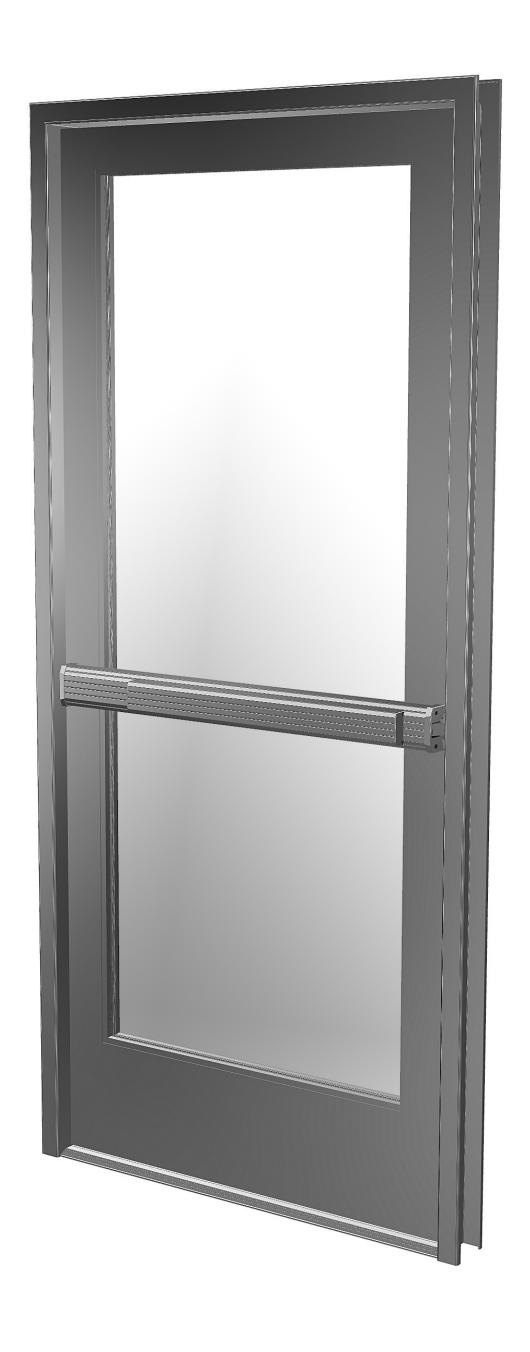
CRL JACKSON 1295 RIM PANIC EXIT DEVICE

Phone: (800) 421-6144 • Fax: (866) 921-0531 crlaurence.com • usalum.com • crl-arch.com
ORDER OF ASSEMBLY AND INSTALLATION
|
Tools Required
|
02 |
|---|---|
|
Parts Identification
03 - 04 |
|
|
Door Preparation
05 - 08 |
|
| Remove Door | 05 |
|
1295 Rim Panic Exit Device Installation
|
06 |
| 1295 Rim Panic Exit Device Installation with Optional Rim Lock Cylinder | 07 |
|
1295 Rim Panic Exit Device Installation with Optional Exterior Trim and Rim Cylinder
|
08 |
| Door Hardware Installation | 09 - 13 |
| Installation of Optional Rim Cylinder | 09 |
| Installation of External Trim (Optional) | 10 |
|
Installation of 1295 Rim Panic Exit Device
|
11 |
|
Installation of End Caps and Cover Plates
|
12 |
|
Frame Preparation
|
13 |
| Dogging Pin Options | 14 |
|
Packaged Parts Available
|
15 |
Tools Required
Drill bits: 5/8", 11/64", 13/64", 1-13/32"
Tap: 1/4" x 20 Tape measure Saw horses Drill
Phillips #2 screwdriver Standard screwdriver
Framing square/straight edge
1/2" Masking tape Center punch Flat File Round File
Jigsaw with metal cutting blade
NOTE: Any modifications, other than those specified in this document, could result in this product's failure to meet UL safety ratings and void the manufacturer's warranties.
The rapidly changing technology within the architectural aluminum products industry demands that U.S. Aluminum reserve the right to revise, discontinue or change any product line, specification or electronic media without prior written notice.
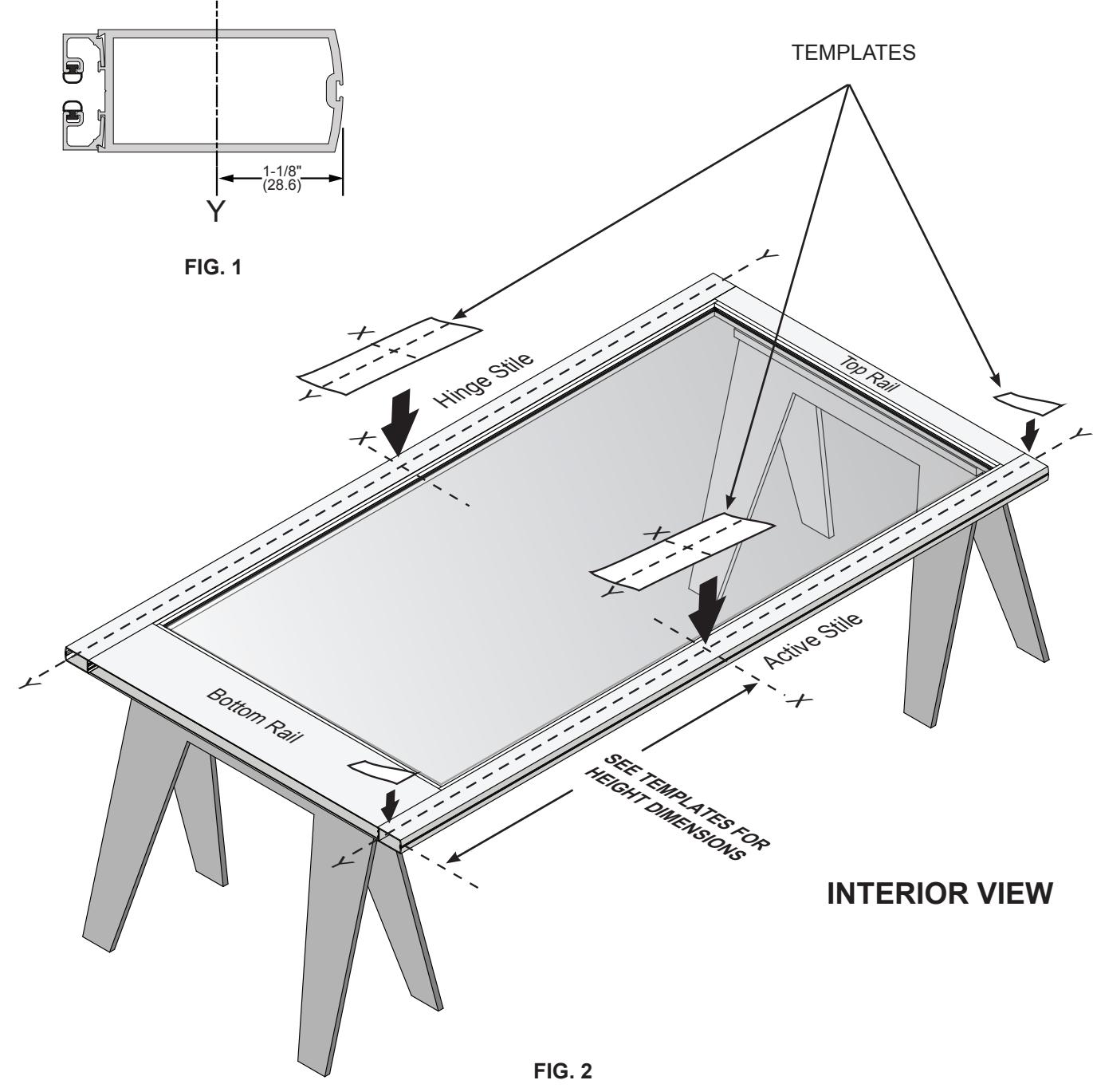
NOTE: Dimensions in parentheses ( ) are millimeters unless otherwise noted.
PARTS IDENTIFICATION
| FASTENERS PROVIDED | ||||||
|---|---|---|---|---|---|---|
|
CALL
OUT |
QTY. | FASTENER |
FASTENER
DESCRIPTION |
PART |
USED WITH
PART NUMBER |
|
| A | 4 |
3/16" Pan Head
Screw |
302670
Dogging Assembly |
|||
| B | 1 |
1/4"-20 x 1/2"
Pan Head SMS |
Base End Plate
(Included in 302654 Base Cover Plate Pkg.) |
|||
| © | 4 | 8-32 x 1/4" FHMS |
302654
Base Cover Plate Pkg. |
|||
| D | 2 |
10-24 x 5/8"
Oval Head Screw |
302436 "C" Type
Surface Mounted Strike |
|||
| E | 2 | 1-7/8" (47.6 mm) |
DL911
Rim Key Cylinder |
|||
| F | 2 | 10-32 x 2-1/8" FHMS |
9500LV02
Flat Handle Lever Trim 9500LV01 Round Handle Lever Trim |
|||
NOTE: Any modifications to this product, other than those specified in this document may void the warranty as this product will no longer meet the UL safety rating requirements this product was tested and intended for.
PARTS IDENTIFICATION
| PARTS LIST | ||||||
|---|---|---|---|---|---|---|
|
CALL
OUT |
QTY. | PART | PART NO. | DESCRIPTION | ||
| G | 1 |
302674 and
30267448 |
Cover Plate | |||
| H | 1 | DL911 |
Optional Rim
Key Cylinder |
|||
| I | 1 | 302436 |
"C" Type Surface
Mounted Strike |
|||
| J | 1 | 302501 |
"S" Type Surface
Mounted Strike |
|||
| K | 1 |
9500LV02/
9500LV01 |
9500LV02
Flat Handle Lever Trim (Shown) 9500LV01 Round Handle Lever Trim (Similar) |
|||
DOOR PREPARATION
REMOVE DOOR
- 1. Place door horizontally on stands, interior side up.
- 2. Mark stile centerlines Y-lines, 1-1/8" (28.6) from outside edge for all stile widths. (Fig. 1)
- 3. Mark stile X-lines per template instructions. (Fig. 2)
- 4. Attach corresponding templates. (Fig. 2)
DOOR PREPARATION – LAYOUT SELECTION
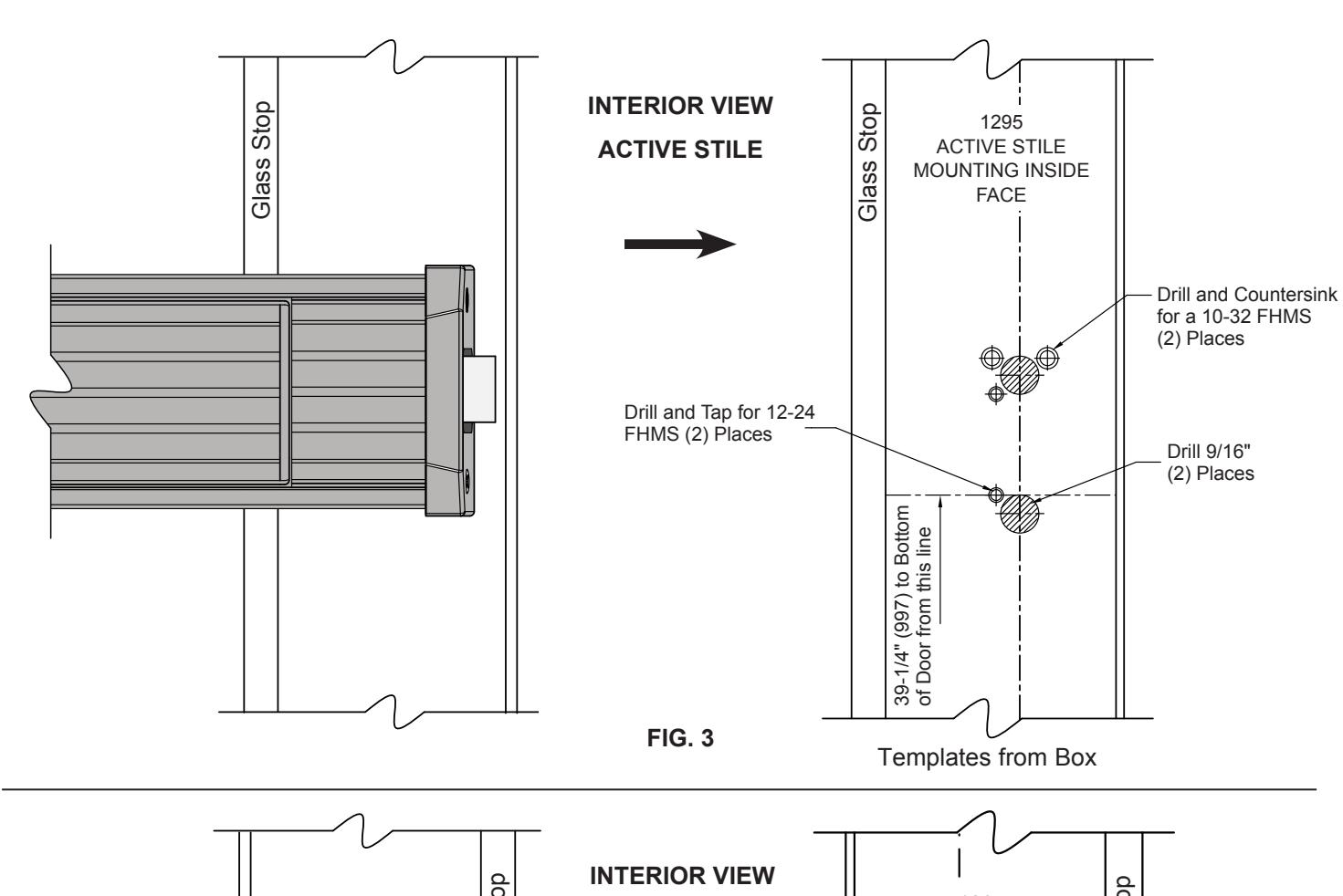
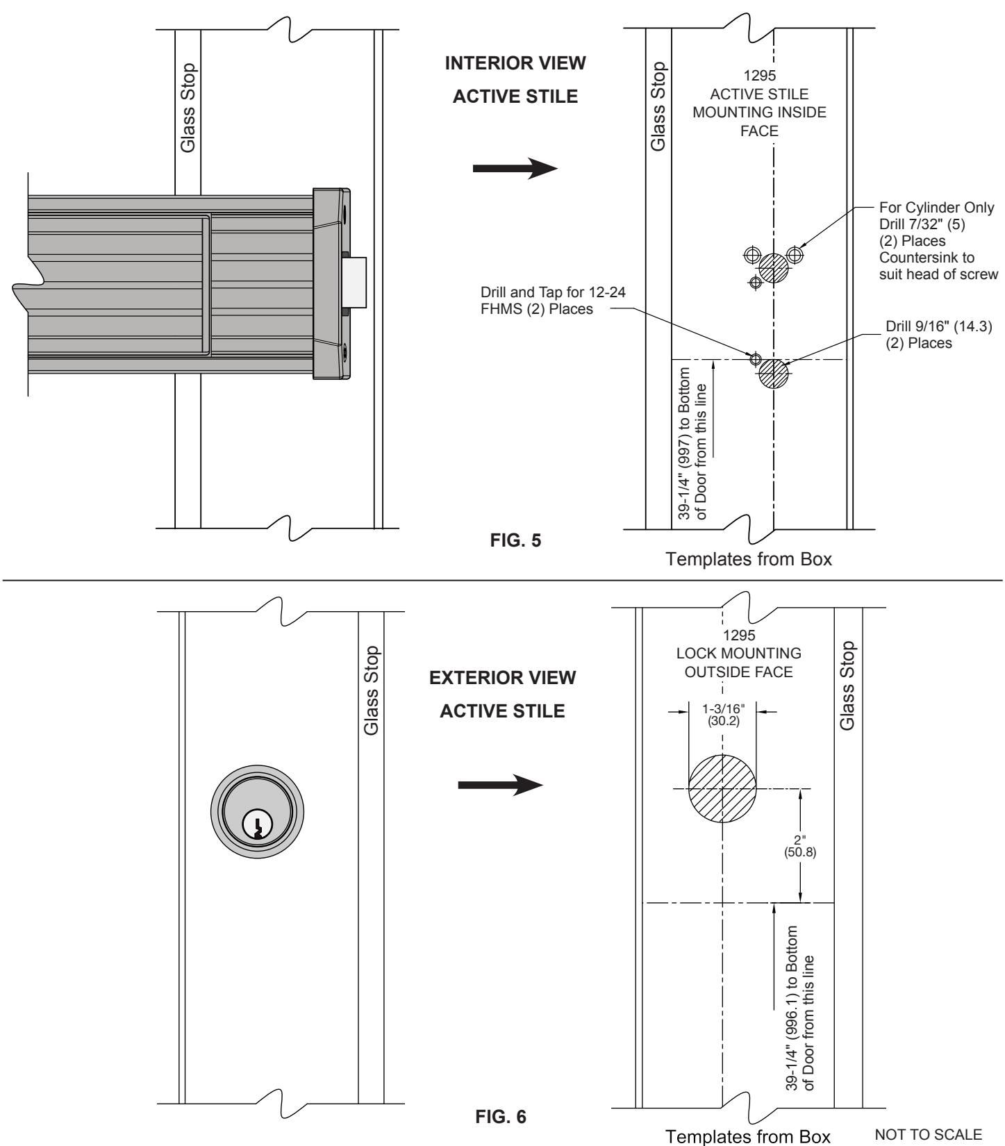
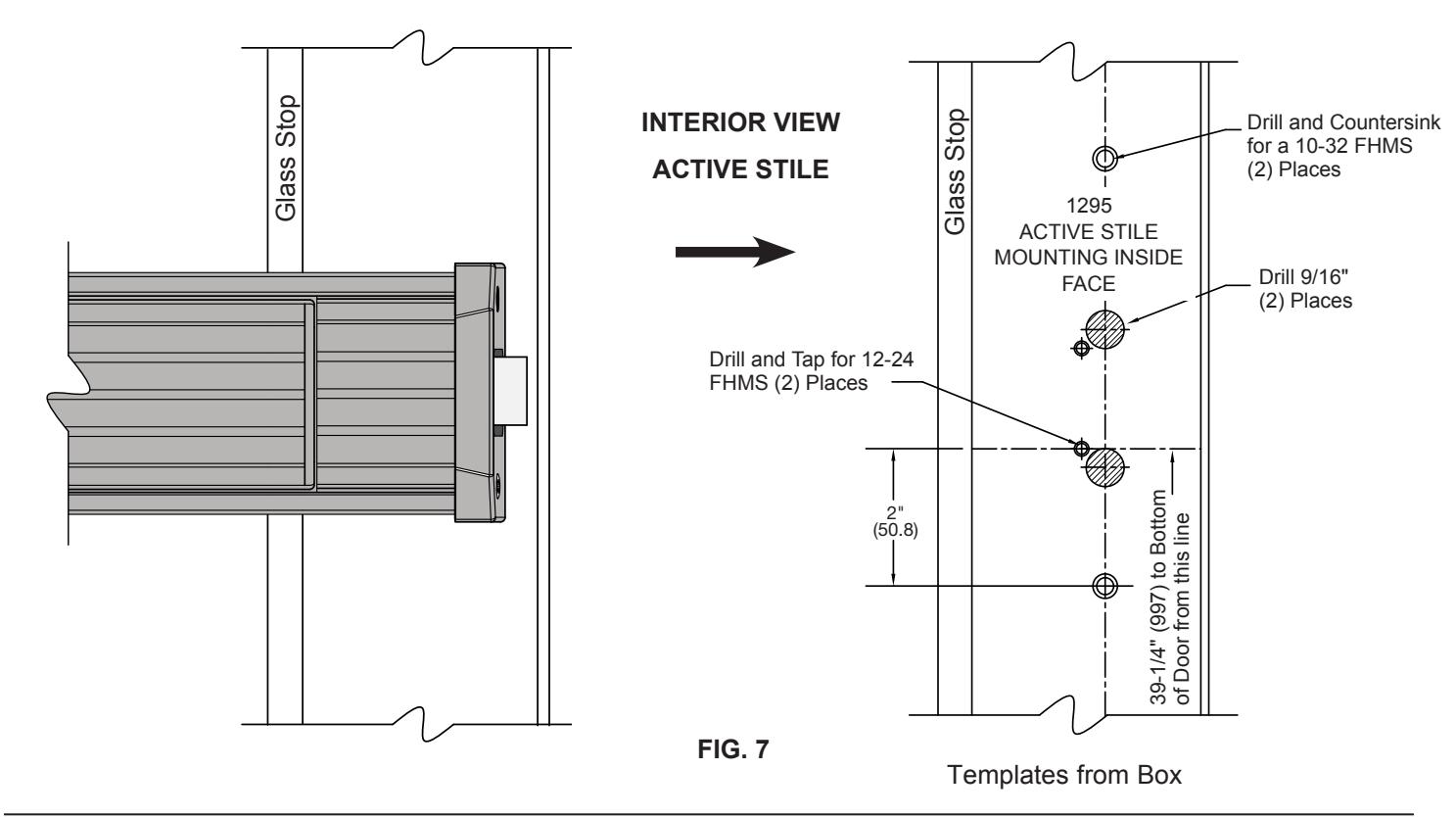
1295 RIM PANIC EXIT DEVICE INSTALLATION
DOOR PREPARATION – LAYOUT SELECTION
1295 RIM PANIC EXIT DEVICE INSTALLATION WITH OPTIONAL RIM LOCK CYLINDER
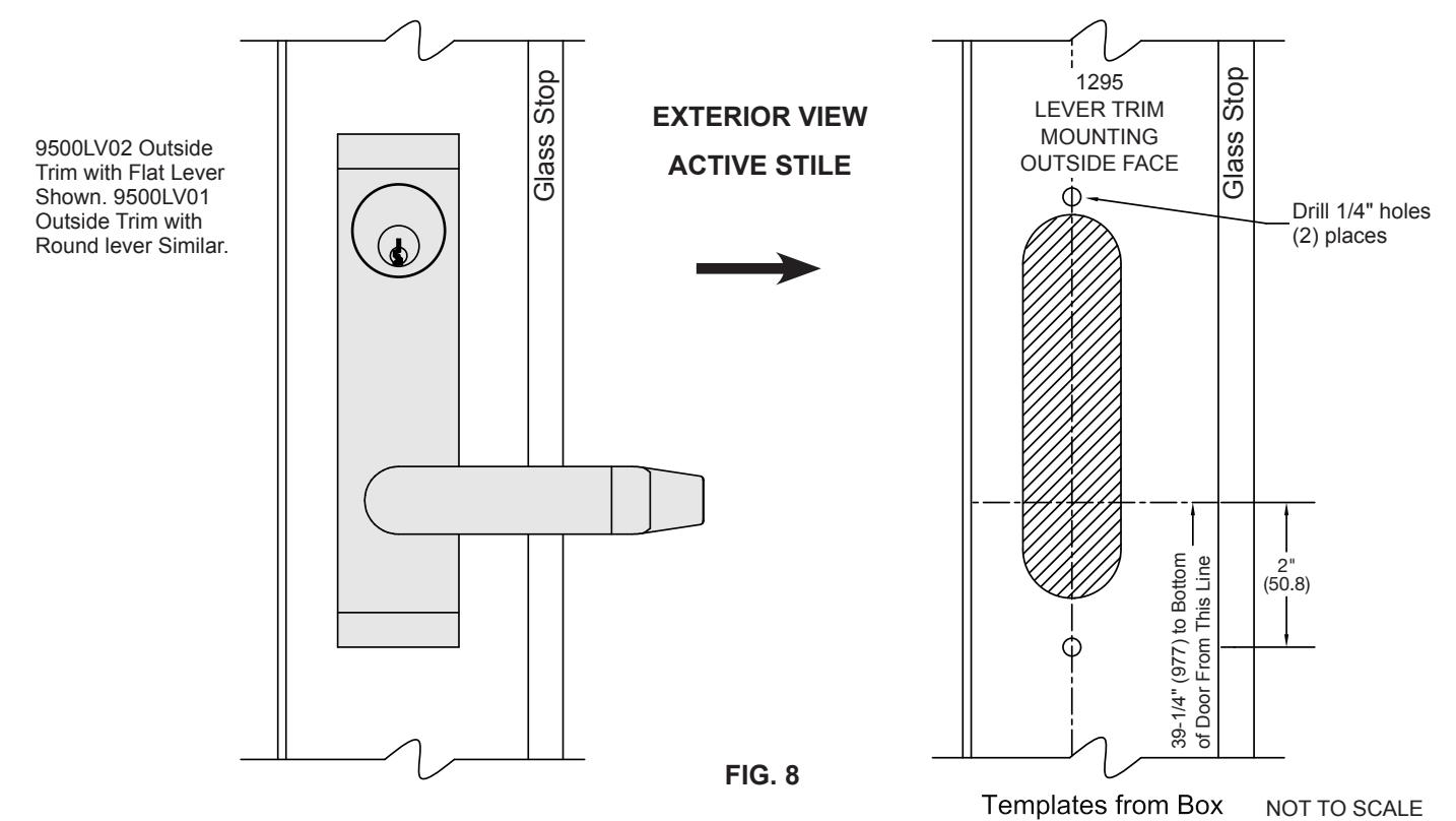
DOOR PREPARATION – LAYOUT SELECTION
1295 RIM PANIC EXIT DEVICE INSTALLATION WITH OPTIONAL EXTERIOR TRIM AND RIM CYLINDER
DOOR HARDWARE INSTALLATION INSTALLATION OF OPTIONAL RIM CYLINDER
NOTE: Optional Rim Cylinder must be installed before attaching exit device.
1. Attach the Rim Cylinder on door stile with (2) 1-7/8" (47.6 mm) Breakaway Screws provided. Fig. 9
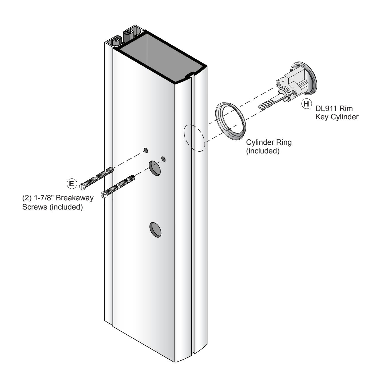
FIG. 9
DOOR HARDWARE INSTALLATION (CONTINUED) INSTALLATION OF EXTERNAL TRIM (OPTIONAL)
NOTE: Exterior trim must be installed before attaching exit device.
1. Attach the exterior trim with F (2) #10 x 2-1/8" Flat head screws provided shown in Fig. 10.
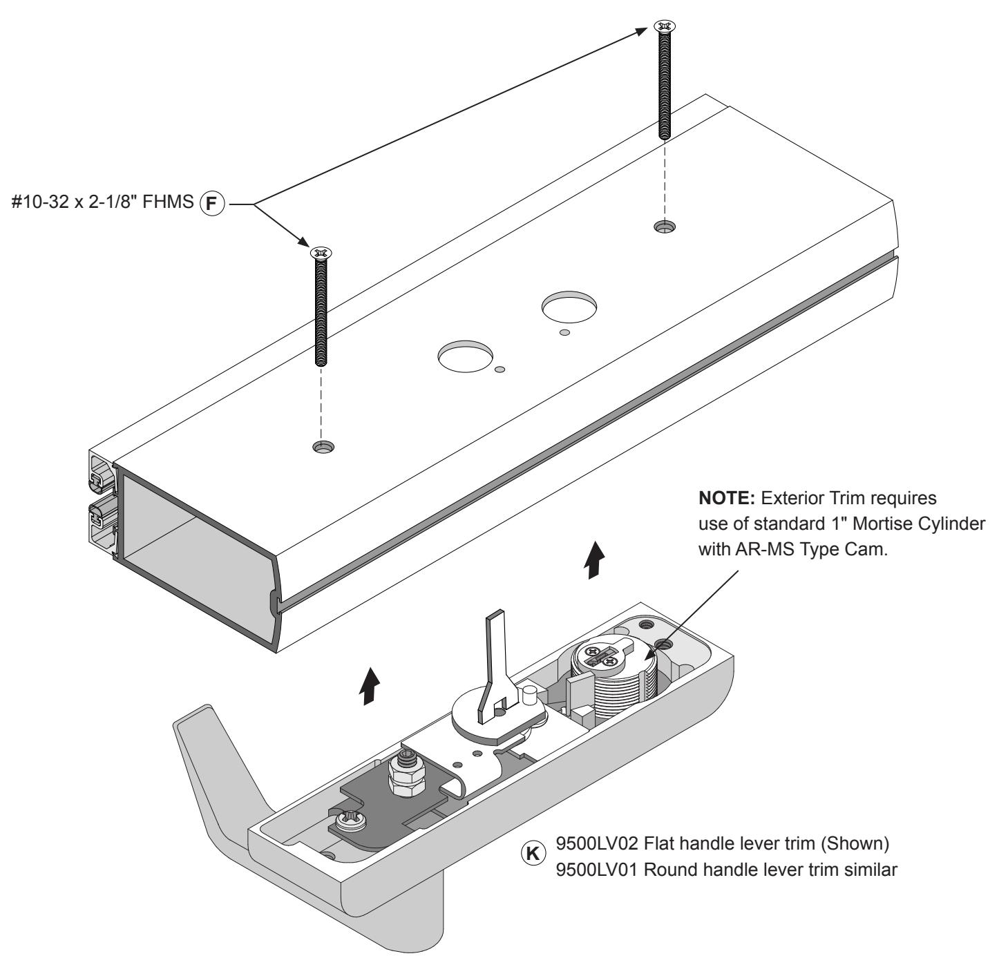
FIG. 10
INSTALLATION OF 1295 RIM PANIC EXIT DEVICE DOOR HARDWARE INSTALLATION (CONTINUED)
1. Attach exit panic device to door with (2) 12-24 x 3/4" FHMS on active stile and (1) 1/4"-20 x 1/2" PHSMS at end cap bracket on inactive stile as shown in Fig. 11. B C
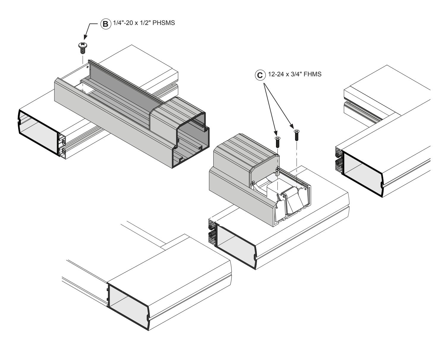
FIG. 11
INSTALLATION OF END CAPS AND COVER PLATES DOOR HARDWARE INSTALLATION (CONTINUED)
- 1. Slide the (2) base cover plates 302674 and 30267448 in place. G
- 2. Attach both end caps to the previously attached end cap brackets with (4) 8-32 x 1/4" FHMS Refer to (Fig.12). C
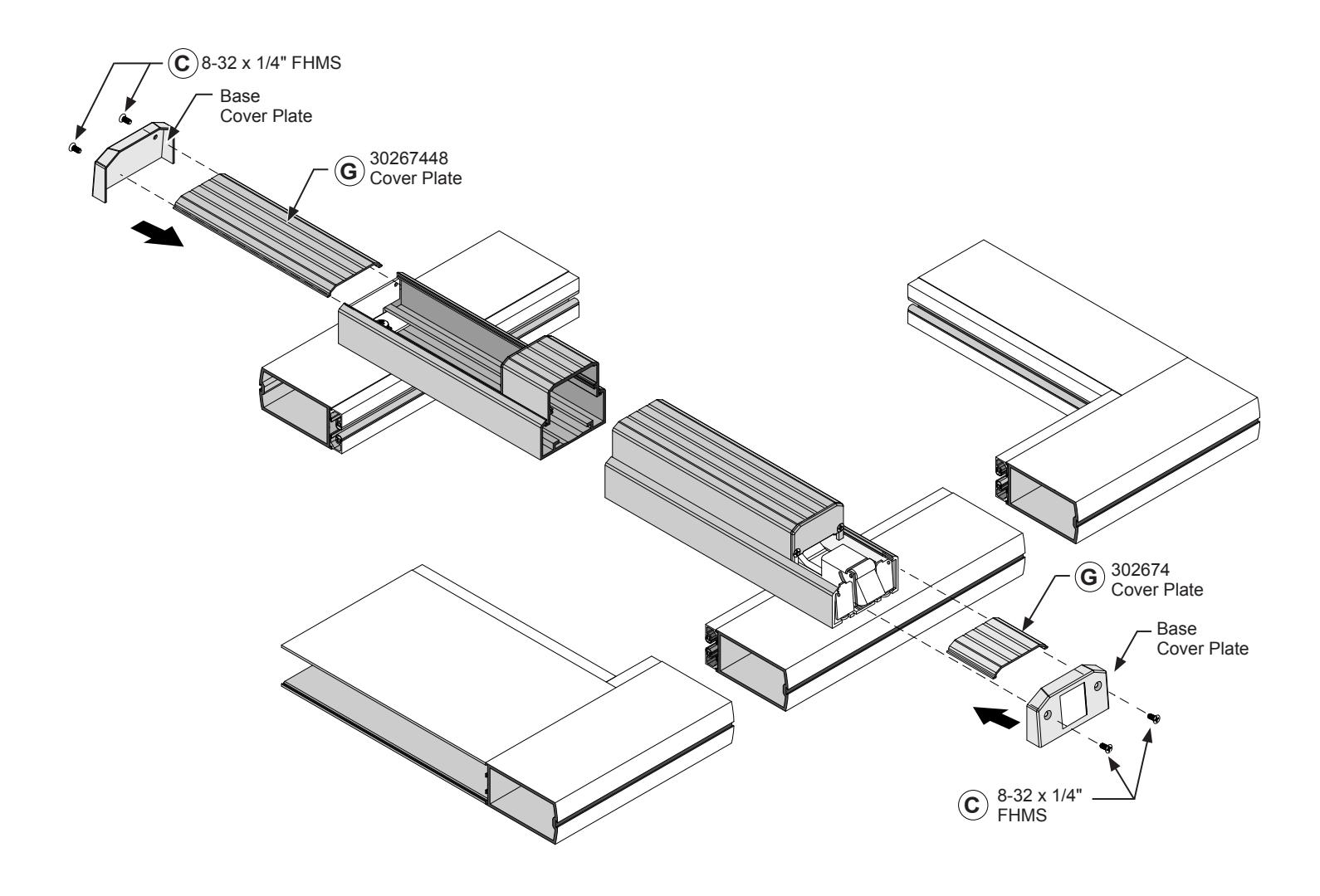
FIG. 12
DOOR HARDWARE INSTALLATION (CONTINUED)
FRAME PREPARATION
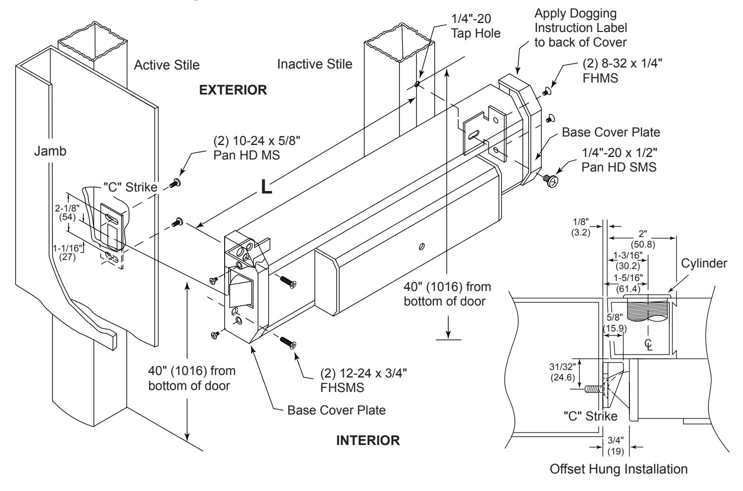
FIG. 13
Mounting Instructions
- 1. Prepare Lock Stile per Template, drill Cylinder mounting holes if required.
- 2. Locate Centerline of Cylinder on exterior of Door and drill if required.
- 3. Trim Tail Piece to fit into Panic Drive Bushing Assembly.
- 4. Mount Cylinder and secure with mounting screws. (Supplied by lock mfg.) If trim is required prepare per Template.
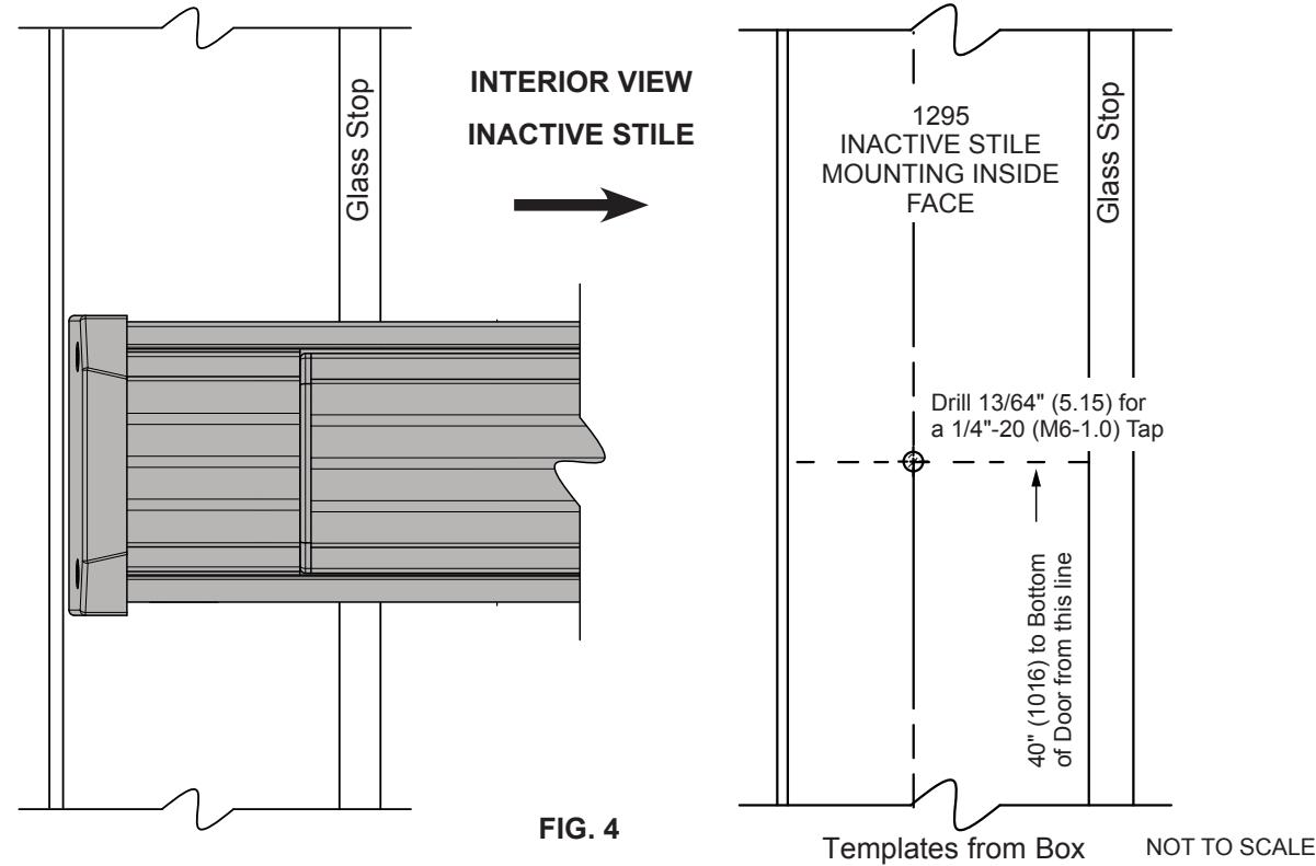
- 5. Locate mounting hole on Inactive Stile. Drill and tap 1/4"-20 Thds. 40" (1016) from the bottom of the Door.
Panic Attachment
- 1. Remove front and rear Base Cover Plates by removing (4) 8-32 x 1/4" Flat HD Screws. Secure active end of panic by installing (2) 12-24 x 3/4" Flat HD MS. Secure inactive end with single 1/4"-20 x 1/2" Pan HD SMS through Base Cover Plate Bracket. Re-install Base Cover Plates on each end of Panic Base.
- 2. To install "C" Strike, locate 10-24 tap holes on Active Stile (2 places).
- 3. Mount and secure "C" Strike.
- 4. Check operation of all parts including Cylinder (if applicable) to assure proper operation.
NOT TO SCALE
DOGGING INSTRUCTIONS
TO DOG Insert Hex Dogging Key (Cat. No. 302796). Turn Key clockwise until it stops. Depress and hold the Push Bar then release the Key. Push Bar will remain depressed. Remove Key. (Fig. 14)
TO UNDOG Insert Hex Dogging Key and turn clockwise until it stops. While depressing Push Bar turn and remove Key. Push Bar will become operable again. (Fig.15)
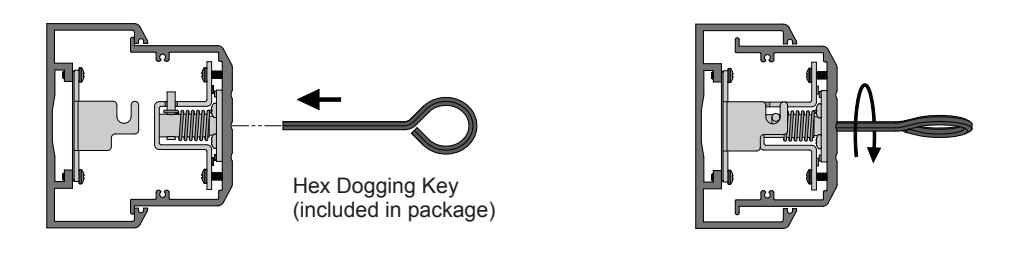
FIG. 15
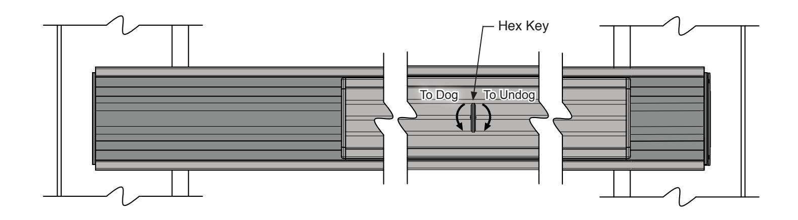
FIG. 16
NOT TO SCALE
FIG. 14
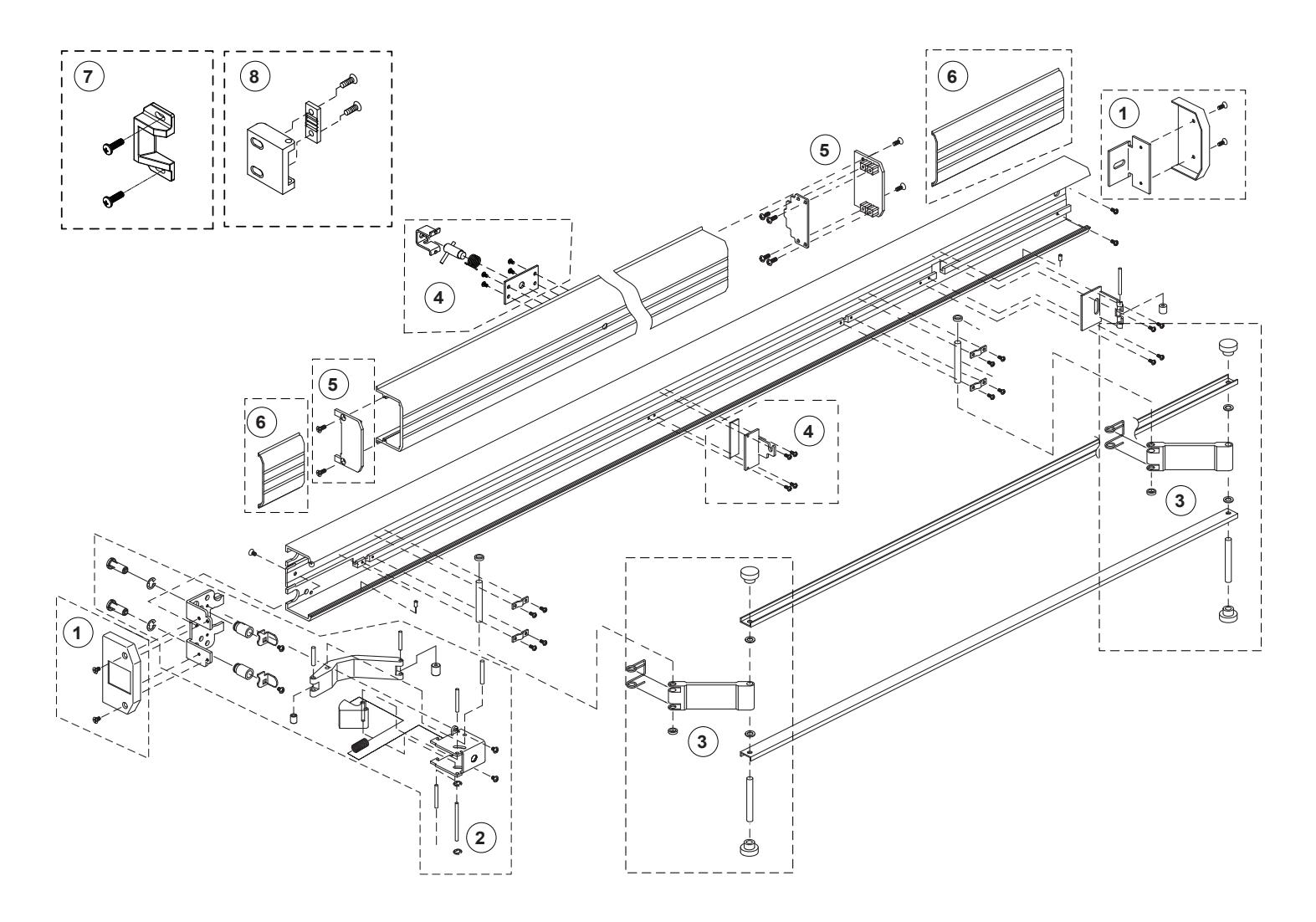
PACKAGED PARTS AVAILABLE
| Assembly No. | Part No. | Description | |
|---|---|---|---|
| 1 | 302654 | Base End Cap Package | |
| 2 | 302679 | Latch Assembly Package | |
| 3 | 302664 | Control Arm Hardware Package | |
| 4 | 302670 | Dogging Assembly | |
| 5 | 302650 | Push Pad End Cap Package | |
| 6 | 302674 | Cover Plate Package - Ribbed - 3/0 Panic | |
| 6 | 30267448 | Cover Plate Package - Ribbed - 4/0 Panic | |
| 6 | 302674S | Cover Plate Package - Smooth - 3/0 Panic | |
| 7 | 302436 | "C" Type - Surface Mounted Strike | |
| 8 | 302501 | "S" Type - Surface Mounted Strike | |
| Not Shown | 302796 | Dogging Hex Key (2 Pkg.) | |