Jackson 1275 SVR Installation Instructions
Open the original PDF document
View PDFINSTALLATION INSTRUCTIONS
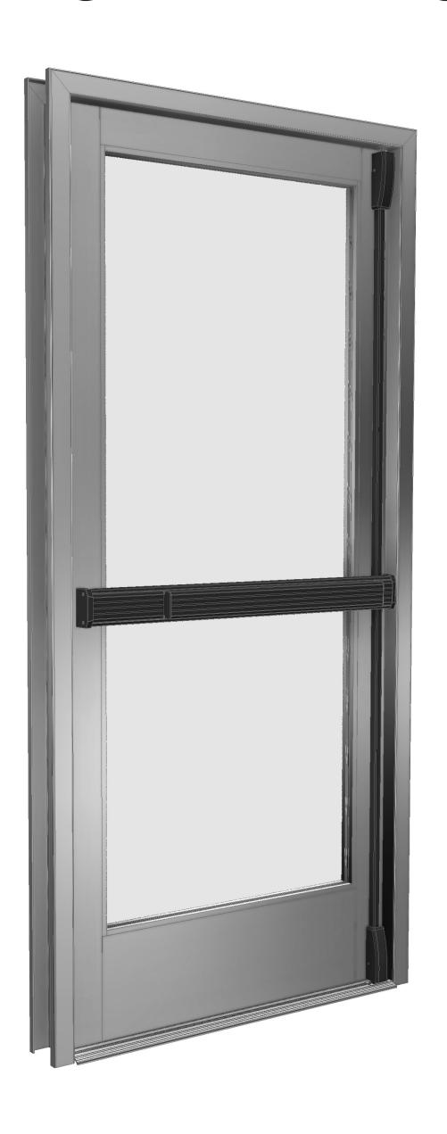
CRL JACKSON 1275 SURFACE VERTICAL ROD PANIC EXIT DEVICE

Phone: (800) 421-6144 • Fax: (866) 921-0531 crlaurence.com • usalum.com • crl-arch.com
CRL JACKSON PANIC EXIT DEVICE - 1275 SURFACE VERTICAL ROD
ORDER OF ASSEMBLY AND INSTALLATION
|
TOOLS REQUIRED
02 |
|
|---|---|
| PARTS IDENTIFICATION03 - 04 | |
|
DOOR PREPARATION
05 - 08 |
|
|
LAYOUT SELECTION
06 - 08 |
|
|
1275 EXIT DEVICE INSTALLATION
06 - 07 |
|
| 1275 EXIT DEVICE WITH LOCK CYLINDER AND EXTERIOR TRIM | 08 |
|
DOOR HARDWARE INSTALLATION
09 - 15 |
|
| INSTALL MORTISE CYLINDER LOCK AND EXTERIOR TRIM (OPTIONAL)09 | |
| INSTALL UPPER AND BOTTOM LATCH BRACKET ASSEMBLIES10 | |
|
INSTALL 1275 EXIT DEVICE
11 |
|
| ROD LINKAGE ADJUSTMENTS12 | |
| CONNECTION OF LINKAGE RODS TO 1275 EXIT DEVICE13 | |
| OPERATIONS CHECK AND DOGGING INSTRUCTIONS14 | |
| INSTALL END CAPS AND COVER ASSEMBLIES15 | |
|
FRAME PREPARATION AND STRIKE INSTALLATION
16 - 17 |
|
| PACKAGED PARTS AVAILABLE | 18 |
TOOLS REQUIRED
Drill bits: 1/4", 9/32", 7/32", 3/8", 11/16", 7/8", 1-1/4"
Taps: 1/4-20, 10-32, 8-32
Tape measure Saw horses Drill
Phillips #2 screwdriver
Standard screwdriver Framing square/straight edge 1" Masking tape Center punch Flat Metal File Round Metal File Jigsaw with metal cutting blade
NOTE: Any modifications, other than those specified in this document, could result in this product's failure to meet UL safety ratings and void the manufacturer's warranties.
PARTS IDENTIFICATION
| FASTENERS AND PARTS LIST | |||||
|---|---|---|---|---|---|
|
CALL
OUT |
QTY. | FASTENER |
FASTENER
DESCRIPTION |
PART |
USED WITH
PART NUMBER |
| A | 4 | 10-32 x 7/8" FHMS |
302652
Base End Cap Assembly |
||
| B | 1 | 1/4"-20 x 1/2" PHMS |
302652
Base End Cap Assembly |
||
| © | 1 | 1/4"-20 x 1-1/4" FHMS |
Upper Latch
Bracket Assembly Included in 302408 |
||
| D | 1 | 1/4"-20 x 1-1/4" FHMS | ⊕ • • • • • • • • • • • • • • • • • • • |
3028477
Upper Rod and Latch Assembly |
|
| E | 1 | 1/4"-20 x 1-1/4" FHMS |
Bottom Latch
Bracket Assembly Included in 302408 |
||
| F | 1 | 1/4"-20 x 1-1/4" FHMS |
302854
Bottom Rod and Latch Assembly |
||
| G | 10 | 8-32 x 1-1/4" FHMS |
3028527 and 302856
Upper and Bottom Rod Cover Base Assembly |
||
| H | 4 | 6-32 x 1/4" FHMS |
302841
Upper and Bottom Latch Cover Assembly |
||
| 1 | 2 | 10-16 x 3/4" FHDS | () () () () () () () () () () () () () ( |
(302113 Set)
Upper Strike Assembly |
|
| J | 2 | 8-18 x 1/2" FHDS |
(302113 Set)
Bottom Strike Assembly |
||
PARTS IDENTIFICATION
| FASTENERS AND PARTS LIST | |||||
|---|---|---|---|---|---|
|
CALL
OUT |
QTY. | FASTENER |
FASTENER
DESCRIPTION |
PART |
USED WITH
PART NUMBER |
| K | 4 | 8-32 x 3/8" FHMS | ⊕ ••• |
302652
Base End Cap Assembly |
|
| (L) | 2 | 10-32 x 2-1/8" FHMS |
Optional 7500LV02628 and
7500LVDT01628 Exterior Trim With Lever Assembly |
||
| PARTS LIST | ||||||
|---|---|---|---|---|---|---|
|
CALL
OUT |
PART | PART NO. | DESCRIPTION | |||
| M |
3028527
and 302856 |
Upper and Bottom Rod Covers | ||||
| N |
302674
and 30267448 |
Base Cover Plates | ||||
| 0 | N/A |
Rod Adjusters
Included in 302741ASM Assembly Package |
||||
| P | 302741 |
Cruciform Rod Activation
Included in 302741ASM Assembly Package |
||||
| Q | DL2170 |
Optional 1" Single
Mortise Cylinder |
||||
DOOR PREPARATION
REMOVE DOOR AND PREPARE PER ATTACHED LAYOUT DRAWING 10-1082-1
- 1. Place the door horizontally on the work stands, interior side up.
- 2. Mark the stile centerlines 1" from the outside edge of the stile. ( Fig. 1)
- 3. Mark the corresponding layouts on to the stile using the vertical centerlines at the specified height. ( Fig. 2)
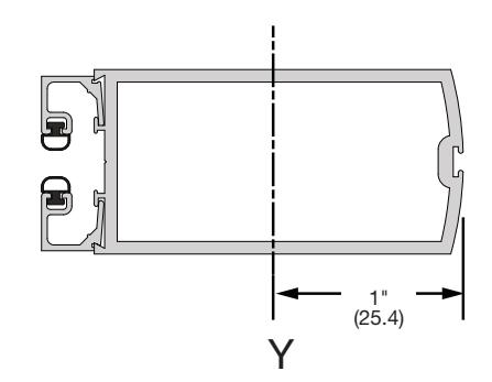
FIG. 1
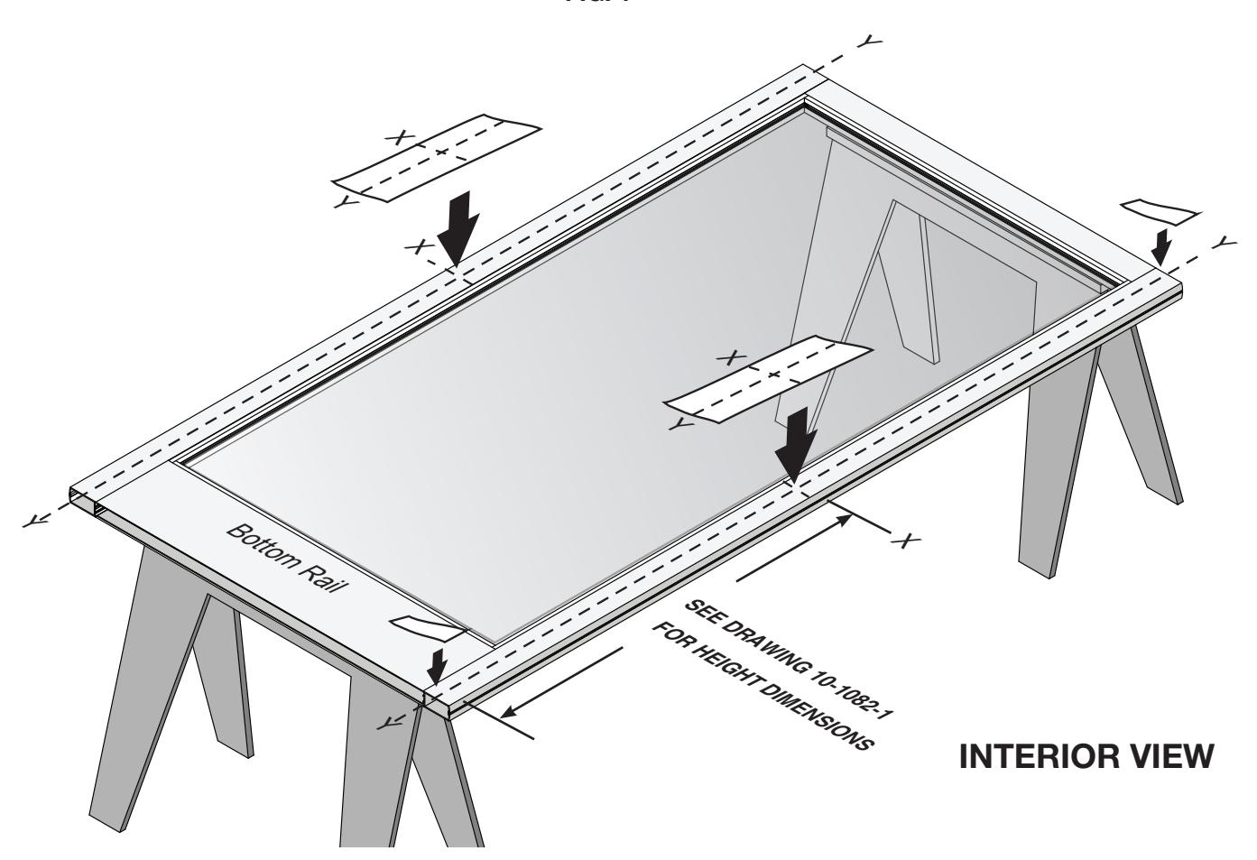
FIG. 2
NOT TO SCALE
DOOR PREPARATION – LAYOUT SELECTION
1275 EXIT DEVICE INSTALLATION - ACTIVE STILE
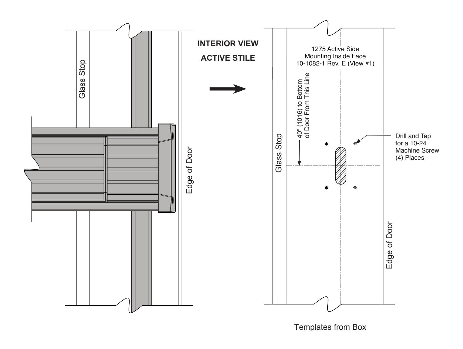
FIG. 3
NOT TO SCALE
DOOR PREPARATION - LAYOUT SELECTION
1275 EXIT DEVICE INSTALLATION - INACTIVE STILE
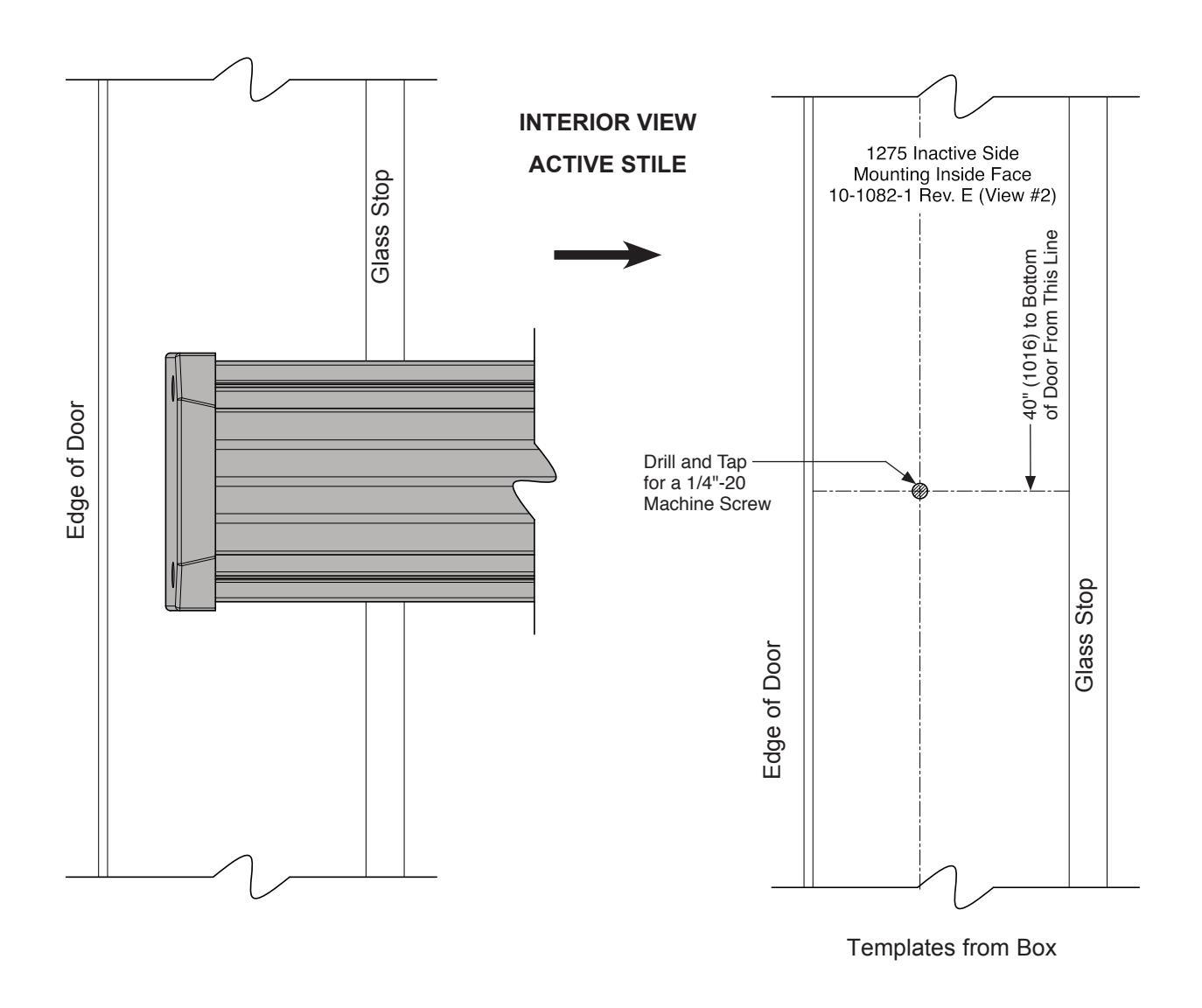
FIG. 4
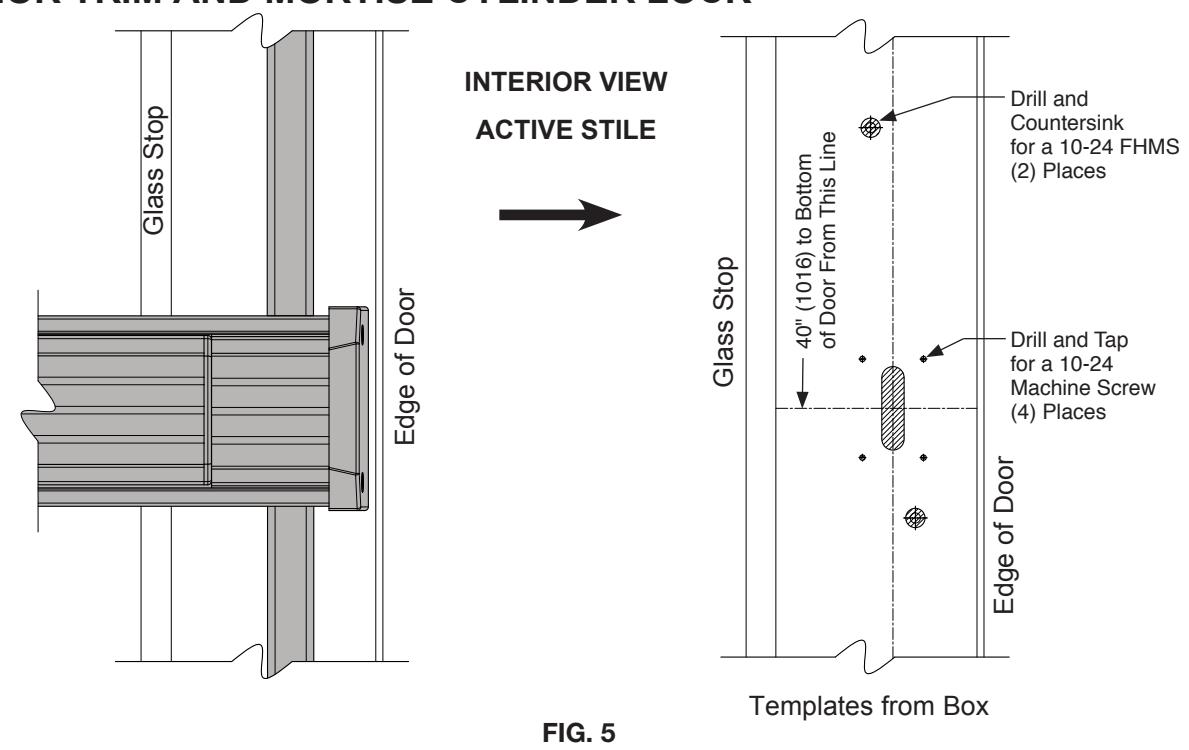
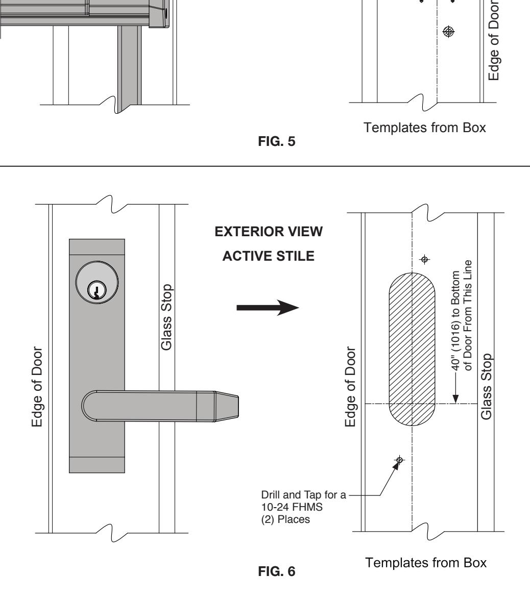
DOOR PREPARATION – LAYOUT SELECTION
1275 EXIT DEVICE INSTALLATION WITH OPTIONAL EXTERIOR TRIM AND MORTISE CYLINDER LOCK
DOOR HARDWARE INSTALLATION
INSTALL OPTIONAL MORTISE CYLINDER LOCK AND EXTERIOR TRIM
NOTE: Exterior trim must be installed before attaching exit device.
1. Attach the exterior trim to the active stile with (2) #10 x 2-1/8" FHMS L
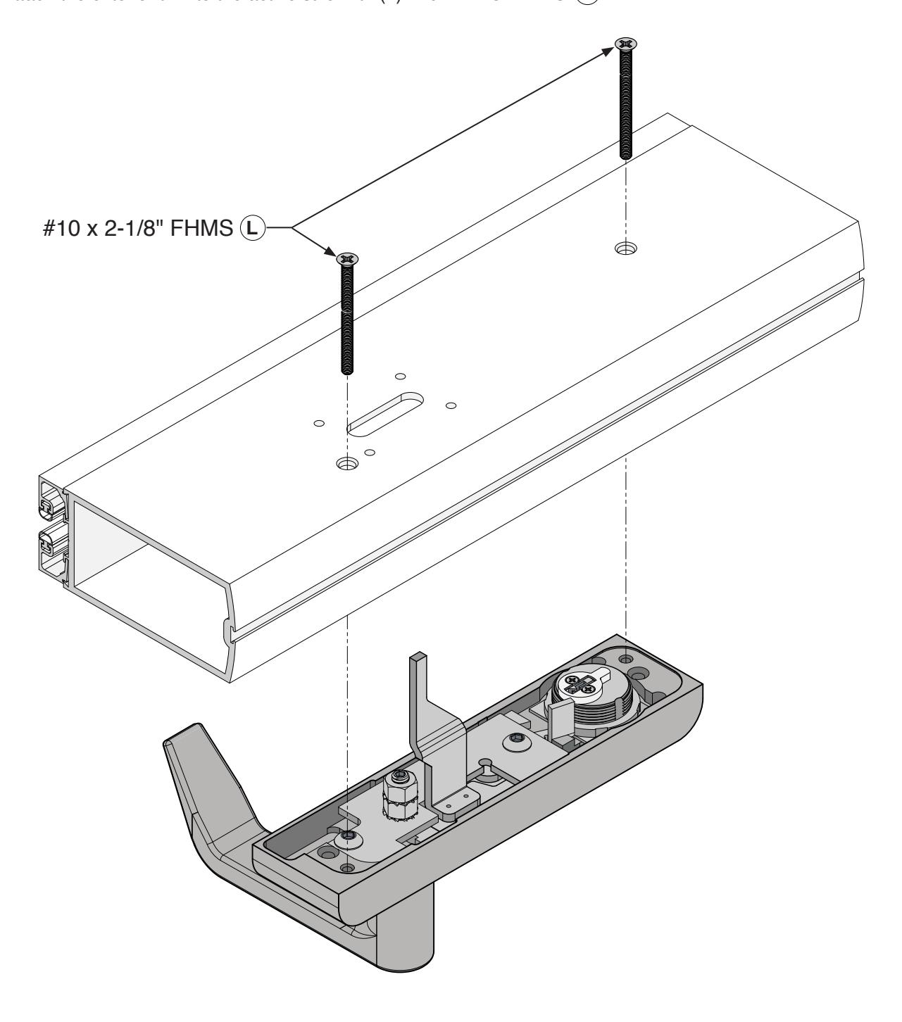
FIG. 7
INSTALL UPPER AND BOTTOM LATCH BRACKET ASSEMBLIES
- 1. Attach the upper and bottom latch bracket assemblies 302408 to the prepped active door stile using (2) 1/4"-20 x 1-1/4" FHMS (C) (E)
- 2. Attach the upper and bottom rod cover base assemblies 3028527 and 302856 to the prepped active door stile using (10) 8-32 x 1-1/4" FHMS
- 3. Attach the upper and bottom rod latch assemblies 3027854 and 3028477 to the latch brackets using (2) 1/4"-20 x 1-1/4" FHMS p F and the bracket pins provided. It is normal for the Latch assemblies to have some play. Secure the pins with the crescent clips provided.
- 4. Attach the upper and bottom rod adjusters 302741 (o) onto the ends of the all-thread linkage rods approximately 1/4".
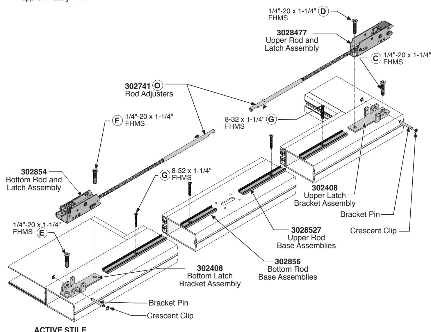
FIG. 8
INSTALL 1275 EXIT DEVICE
- 1. Attach the panic exit device to the active stile with (2) 10-32 x 7/8" FHMS and (1) 1/4"-20 x 1/2" PHMS through the end cap bracket on the inactive stile. A B
- 2. Insert the upper and bottom rod adjusters 302741 into the linkage access holes. O
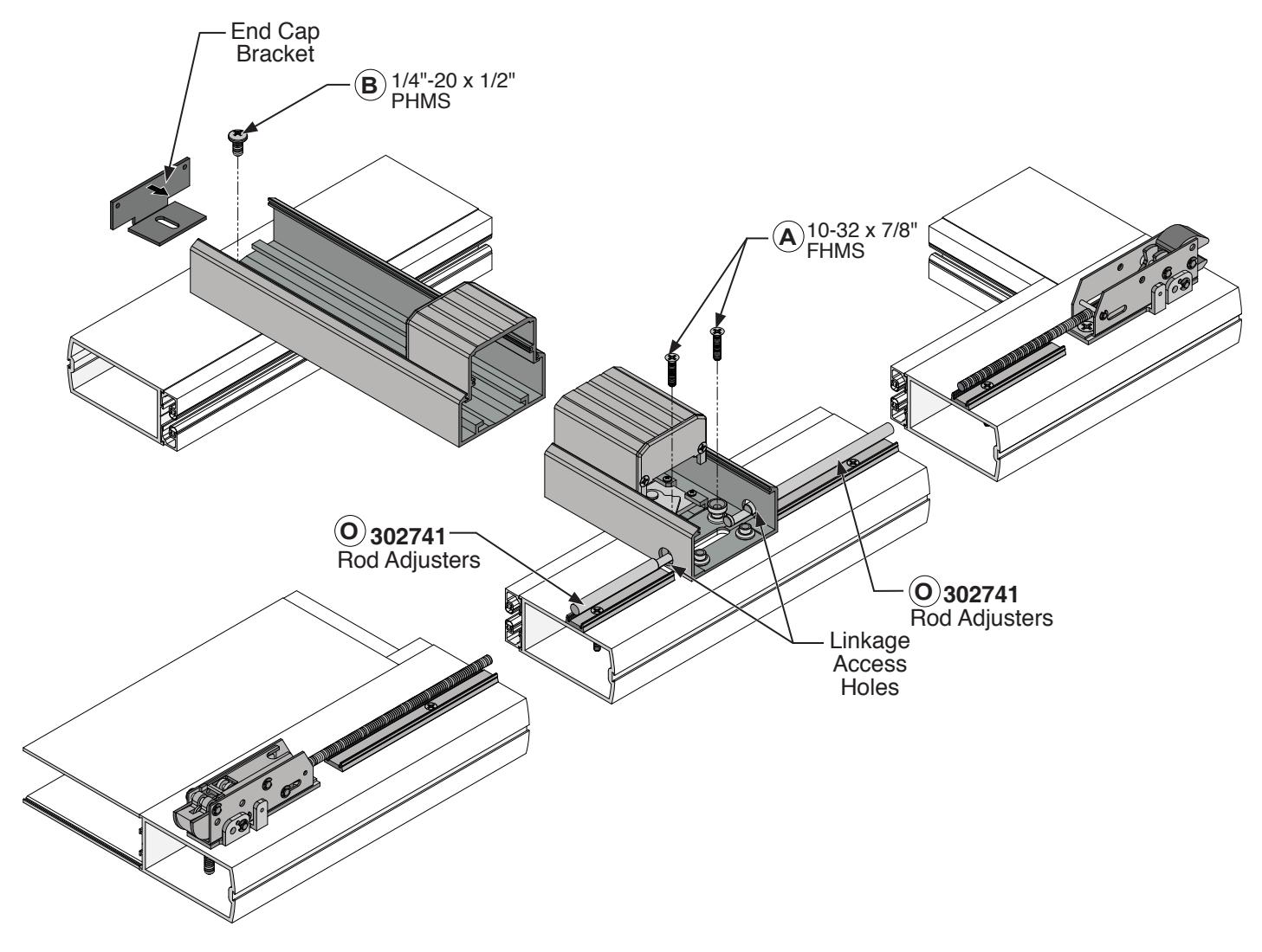
FIG. 9
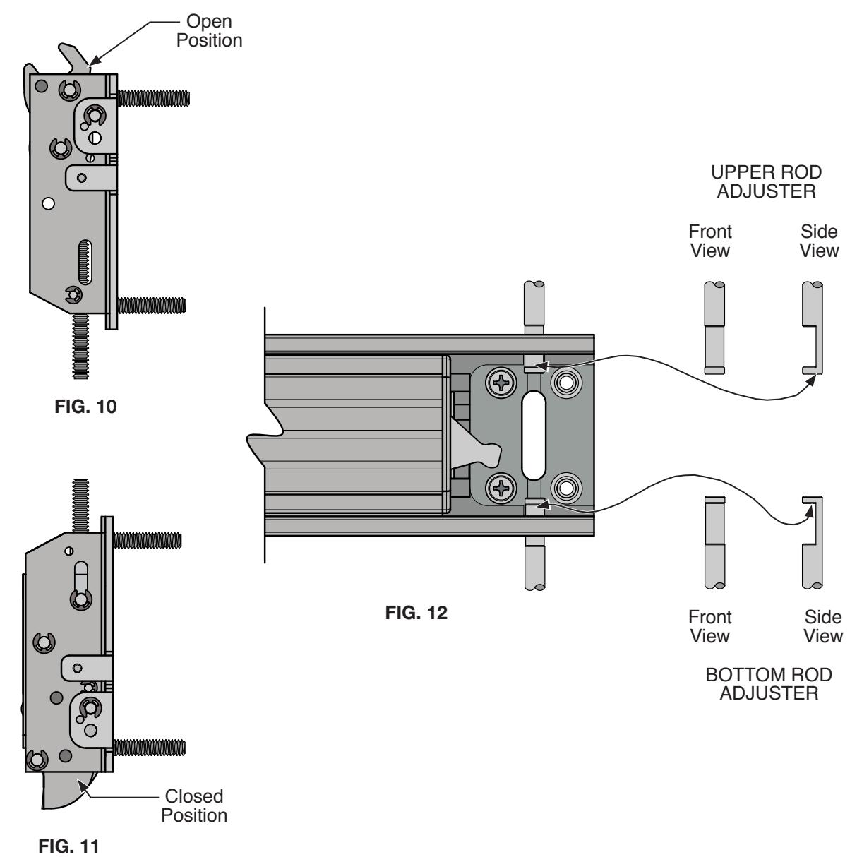
ROD LINKAGE ADJUSTMENTS
UPPER ROD:
- 1. The top latch must be in the open position. ( Fig. 10)
- 2. Turn the adjuster rod so that the end is aligned with the top line marking, just under the words "TOP LATCH" and the rod cut out is facing towards you. (Fig.12)
BOTTOM ROD:
- 1. The bottom latch must be in the closed position. ( Fig. 11 )
- 2. Turn the adjuster rod so that the top edge of the cut-out aligns with the line marking just under the word "LATCH" and the rod cut out is facing towards you. (Fig.12)
NOT TO SCALE
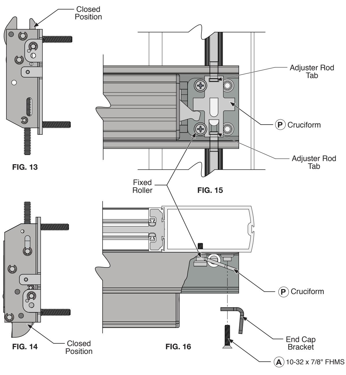
CONNECTION OF LINKAGE RODS TO THE EXIT DEVICE
- 1. Bring the upper latch to the closed position. (Fig. 13) The bottom latch should be in the closed position. (Fig. 14)
- 2. Slide the cruciform Punder the fixed rollers (Fig. 16), capture both the upper and bottom adjuster rod tabs, and hold in place. (Fig. 15)
- 3. Install the end cap bracket over the cruciform (P) with (2) 10-32 x 7/8" FHMS (A) on the active stile. (Fig. 16)
NOT TO SCALE
OPERATIONS CHECK AND DOGGING INSTRUCTIONS OPERATIONS CHECK:
Depress the push bar to assure free movement of the cruciform assembly. Both upper and bottom latches should activate to the open position. The upper latch should drop into the open position, figure 10. The bottom latch should fully retract. If the latches fail to operate as described, review the rod linkage adjustments on page 13. Verify that the latch and rod adjuster positions align with the markings on the panic bar per (Fig. 12).
DOGGING INSTRUCTIONS:
TO DOG Insert hex dogging key (Cat. No. 302796). Turn key clockwise until it stops. Depress and hold the push bar then release the key. Push bar will remain depressed. Remove key. (Fig. 17)
TO UNDOG Insert hex dogging key and turn clockwise until it stops. While depressing push bar turn and remove key. Push bar will become operable again. (Fig.18)
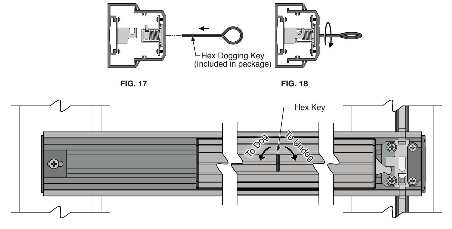
FIG. 19
INSTALL END CAPS AND COVER ASSEMBLIES
- 1. Slide the (2) base cover plates 302674 in place. N
- 2. Attach both end caps with (4) 8-32 x 3/8" FHMS K
- 3. Snap both the upper and bottom base cover plates over the rod base assemblies 3028527 and 302856. M
- 4. Attach the upper and bottom latch covers to the latch brackets using (4) 6-32 x 1/4" FHMS H
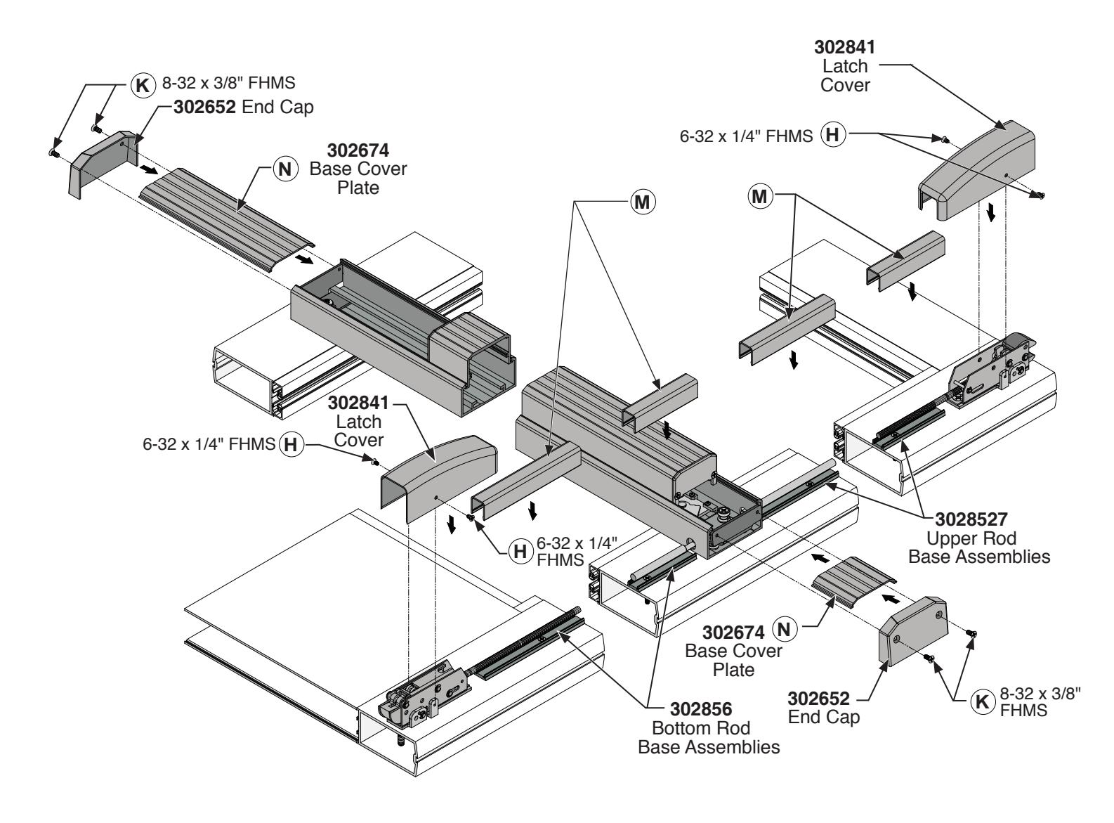
FIG. 20
FRAME PREPARATION RE-ATTACH DOOR TO FRAME
- 1. Make sure that the panic exit device is in the dogged position. Both the upper and bottom latches must clear the frame. Re-attach the door to the frame.
- 2. With the door in place and in the closed position, mark the center line locations on the header and threshold of both the upper and bottom latches.
- 3. Finish the header and threshold preparation using the layout drawings on page 17.
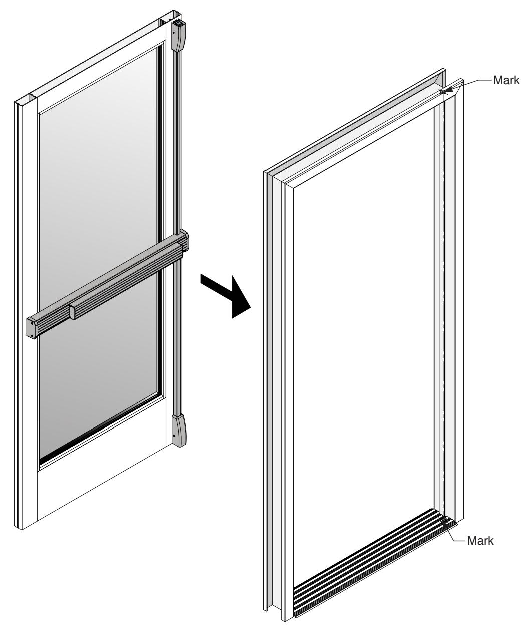
FIG. 21
FRAME PREPARATION
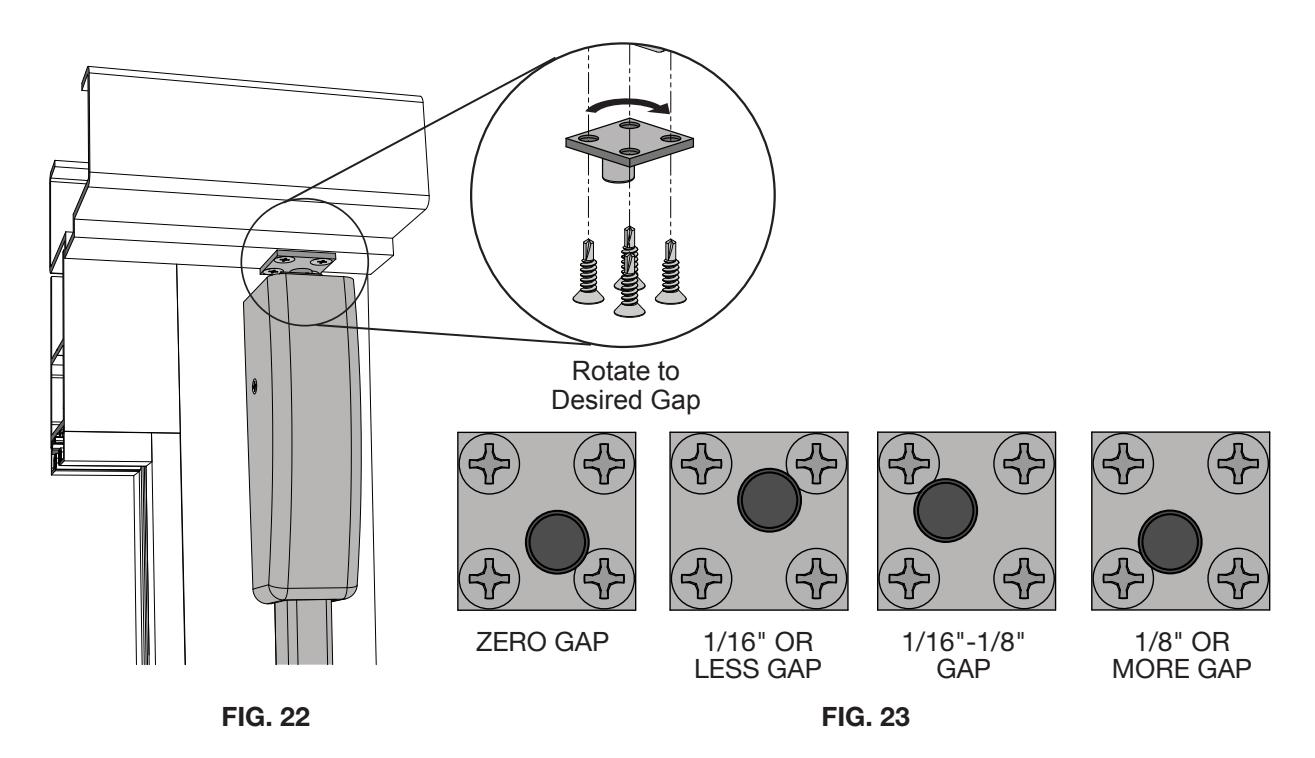
ATTACH UPPER STRIKE
- 1. Attach upper strike, use (4) 10-16 x 3/4" FHDS (Fig. 22) , centering on the mark made in Step 2 of Frame Preparation on page 16. Start with door gap at zero position (Fig.23).
- 2. Test latch engagement.
- 3. Rotate the strike to increase or decrease gap size between top door rail and stop. ( Fig. 23)
NOTE : 1/8" max. vertical clearance between door and header must be maintained. Shim strike if necessary.
ATTACH BOTTOM STRIKE
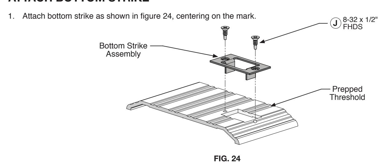
NOT TO SCALE
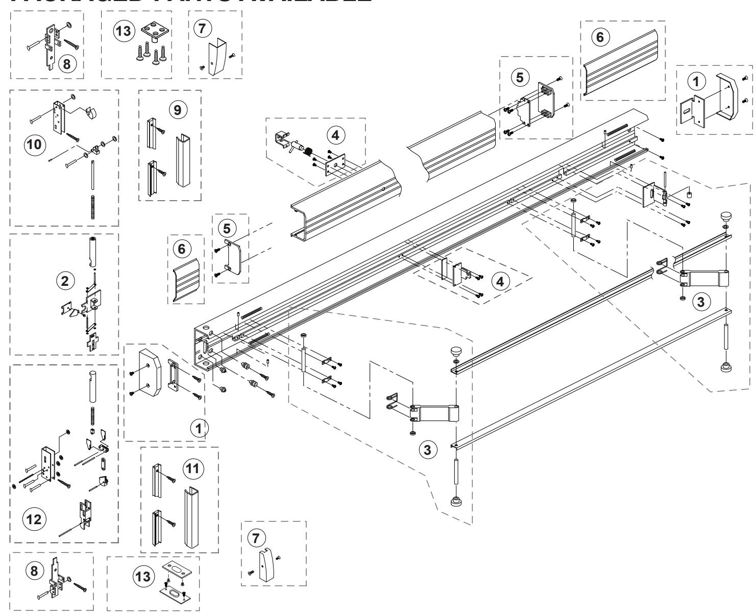
PACKAGED PARTS AVAILABLE
|
Assem.
No. |
Part No. | Description |
Assem.
No. |
Part No. | Description |
|---|---|---|---|---|---|
| 1 | 302652 | Base End Cap Package | 9 | 3028528 | Top Rod Cover Assembly - 8/0 |
| 2 | 302741ASM | Cruciform Activation Assembly | 9 | 3028529 | Top Rod Cover Assembly - 9/0 |
| 3 | 302664 | Control Arm Hardware Package | 10 | 3028477 | Upper Rod and Latch Assembly - 7' |
| 4 | 302670 | Dogging Assembly | 10 | 3028478 | Upper Rod and Latch Assembly - 8' |
| 5 | 302650 | Push-Pad End Cap Package | 10 | 3028479 | Upper Rod and Latch Assembly - 9' |
| 6 | 302674 | Base Cover Plate -Ribbed - 3/0 | 11 | 302856 | Bottom Rod Cover Assembly |
| 6 | 30267448 | Base Cover Plate -Ribbed - 4/0 | 12 | 302854 | Bottom Rod and Latch Assembly |
| 6 | 302674S | Base Cover Plate -Smooth - 3/0 | 13 | 302113 | Upper and Bottom Strike Package |
| 7 | 302841 | Latch Covers (Upper and Bottom) | |||
| 8 | 301856 | Latch Bracket Package | |||
| 9 | 3028527 | Top Rod Cover Assembly - 7/0 |