Jackson 1000 Series Ultimate Overhead Concealed Door Closer Center Hung and Offset Installation Instructions
Open the original PDF document
View PDFINSTALLATION INSTRUCTIONS
CRL JACKSON 1000 SERIES
ULTIMATE OVERHEAD CONCEALED DOOR CLOSER CENTER-HUNG AND OFFSET

Phone: (800) 421-6144 • Fax: (866) 921-0531 crlaurence.com • usalum.com • crl-arch.com
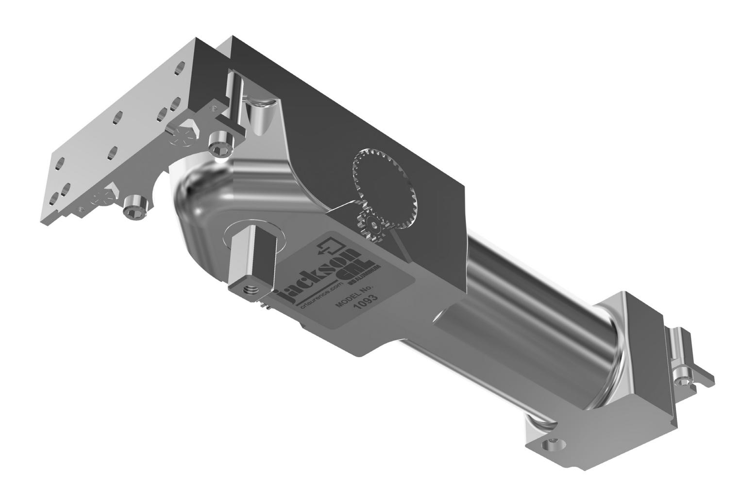
CRL JACKSON 1000 SERIES ULTIMATE OVERHEAD CONCEALED DOOR CLOSER
ORDER OF ASSEMBLY AND INSTALLATION
| ORDER OF ASSEMBLY AND INSTALLATION | 02 |
|---|---|
| INTRODUCTION | 03 |
| MOUNTING DIMENSIONS | 04 |
| CLOSER AND BOTTOM PIVOT INSTALLATION | 05-06 |
| SIDE LOAD ARM AND END LOAD ARM INSTALLATION | 07 |
| SIDE LOAD ARM AND END LOAD ARM ADJUSTMENTS | 08 |
| OFFSET ARM AND OFFSET BOTTOM PIVOT INSTALLATION | 09 |
| SLIDE CHANNEL AND ARM TO SLIDE CHANNEL INSTALLATION | 10 |
| CLOSER ADJUSTMENTS | 11 |

INTRODUCTION
The CRL Jackson® 1000 Series Ultimate Overhead Conealed Door Closer is designed for use with larger and heavier doors weighing up to 1,000 pounds (453 kg). It features an adjustable multi-sizing spring force range of 1 through 6 to allow control of a wide range of door weights and sizes. These 180º degree swing, double acting, non-handed closers are available in dual 90º/ 120º hold-open or non hold open models.
Center-Hung and Offset accessories available include interchangeable extension spindles, center-hung and offset arm and slide-track assemblies, bottom pivots, cover plates, and multiple accessories for use with wood, metal or glass doors.
The rapidly changing technology within the architectural aluminum products industry demands that C.R. Laurence/U.S. Aluminum reserve the right to revise, discontinue, or change any product line, specification, or electronic media without prior written notice.
NOTE: Dimensions in parentheses ( ) are millimeters unless otherwise noted.
MOUNTING DIMENSIONS
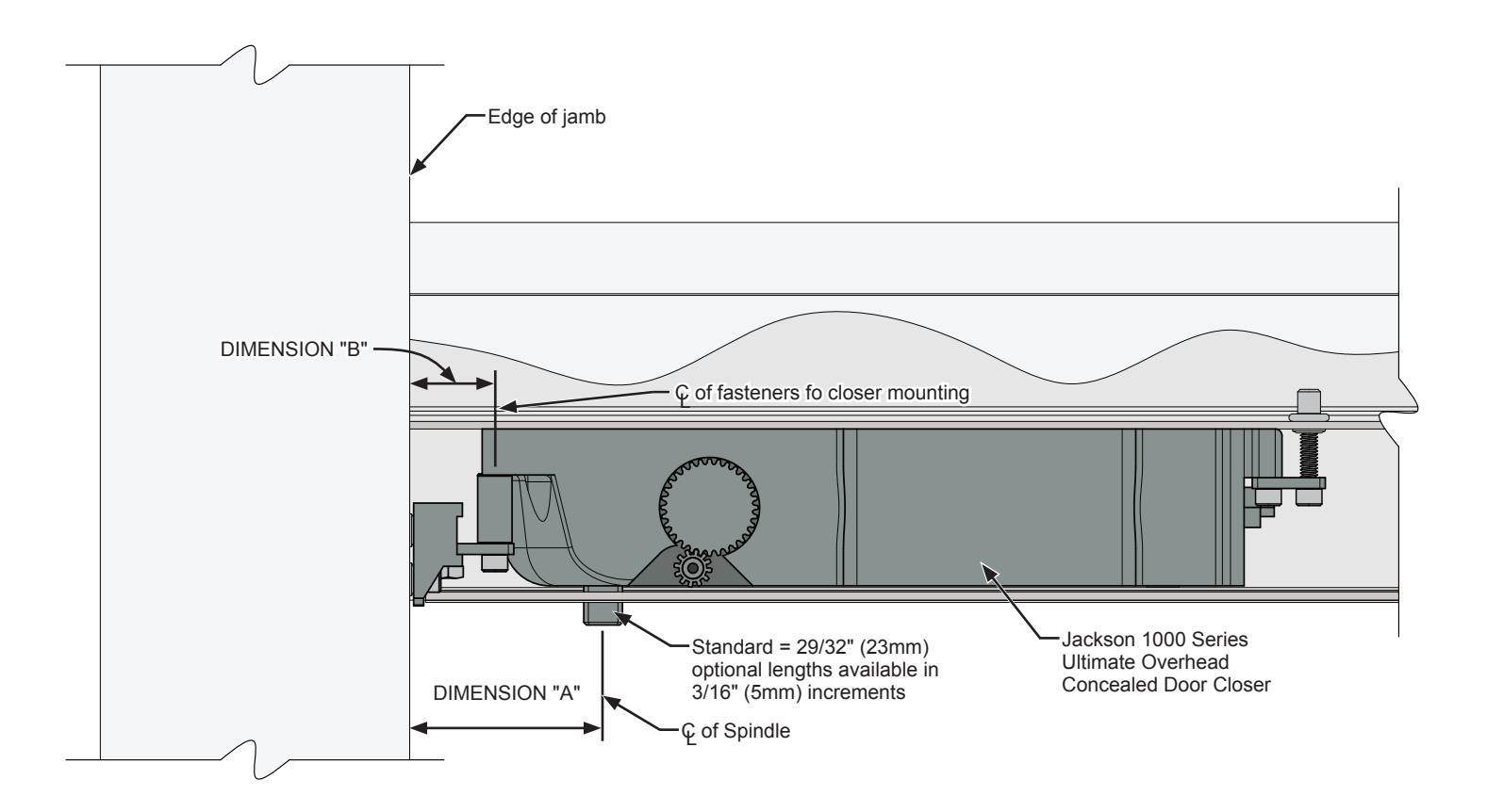
| CLOSER LOCATION INSIDE HEADER | |||||
|---|---|---|---|---|---|
| MODEL | DOOR TYPE | HOLD OPEN | DIMENSION "A" | DIMENSION "B" | |
| J1000 | 90° |
2 3/4"
(69.8mm) |
1 3/16"
(30.1mm) |
||
| CENTER | 120° | ||||
| OFFSET | 90° |
2 3/4"
(69.8mm) |
1 3/16"
(30.1mm) |
||
| 120° | |||||
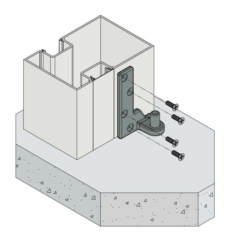
CLOSER INSTALLATION
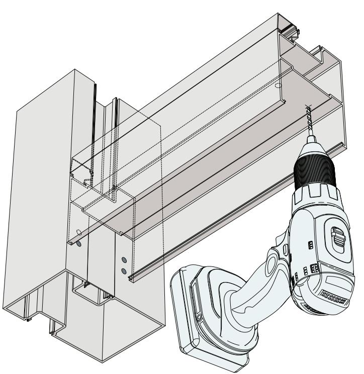

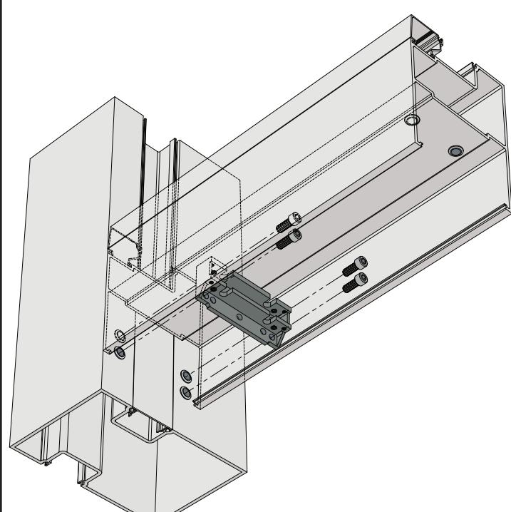
1. Drill holes and insert rivet nuts for 1/4-20 screws. 2. Secure the mounting bracket to the door jamb using (4) 1/4-20 x 5/8" socket head cap screws.
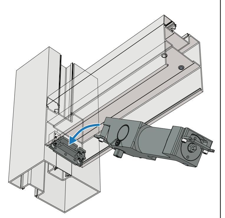
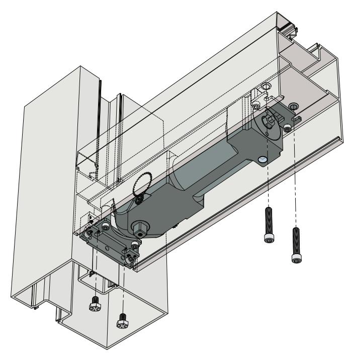
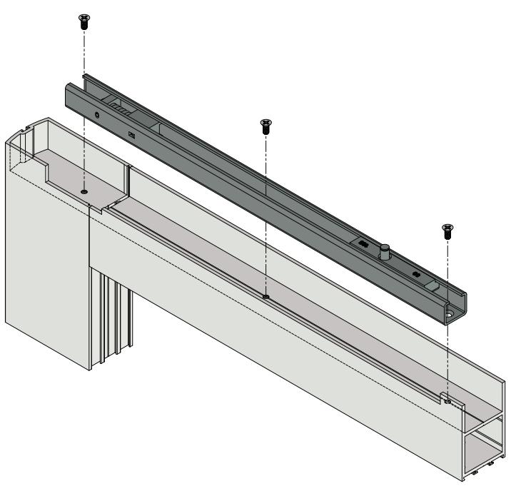
3. Place and hold the closer in place. 4. Secure the closer in place with (2) 1/4-20 x 1-1/4" socket head cap screws and (2) 1/4-20 x 3/4" cap screws
CLOSER INSTALLATION (CONTINUED)
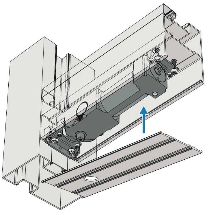
Note:
If you are using the offset application proceed to page 7.
5. Snap-In the cover plate.
BOTTOM PIVOT INSTALLATION
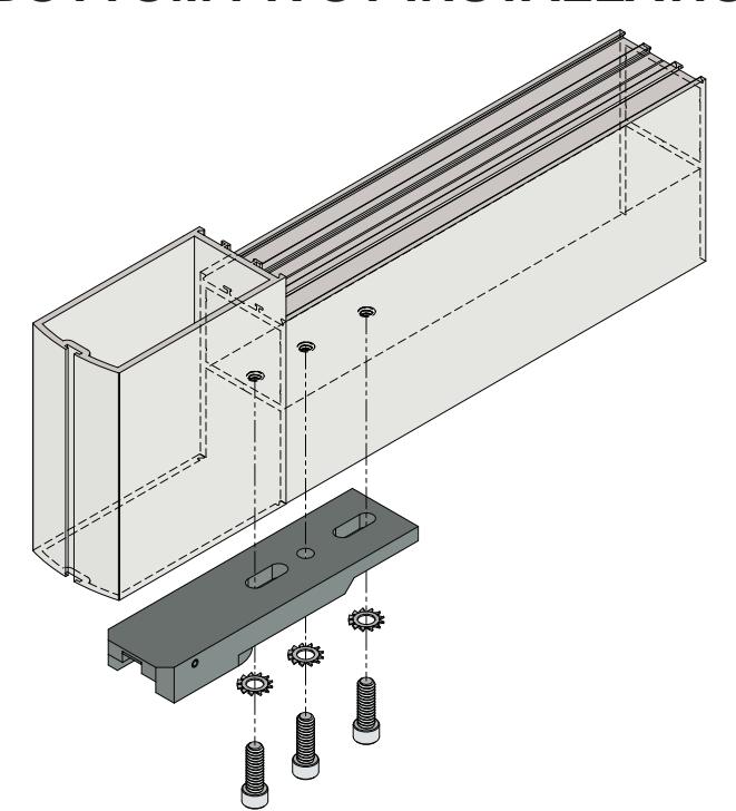
6. Secure the bottom pivot to the door rail with (3) 1/4-20 x 3/4" socket head cap screws.
7. Secure the bottom pivot to the floor with (3) flat head mansonry screws.
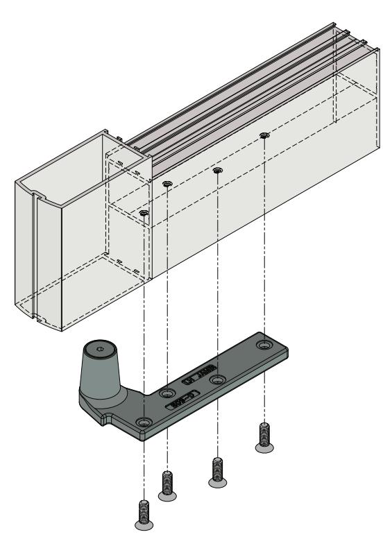
SIDE-LOAD ARM INSTALLATION
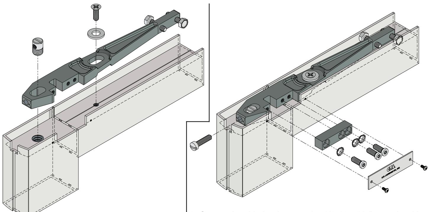
8. Secure the side-load arm to the door rail with (1) 1/4-20 x 3/4" flat head screw and (1) 1/2-13 x 3/4" arm pin, lift the door onto the floor pivot and tilt onto the closer spindle.
9. Secure the side-load arm to the 1/2-13 x 3/4" arm pin with (1) 1/4-20 x 1" fillister head machine screw, secure the clamping block to the arm with (3) 1/4-20 x 3/4" flat head socket cap screws, attach the cover plate to the door rail with (2) #4 x 1/4" pan head machine screws.
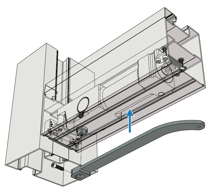
END-LOAD ARM INSTALLATION
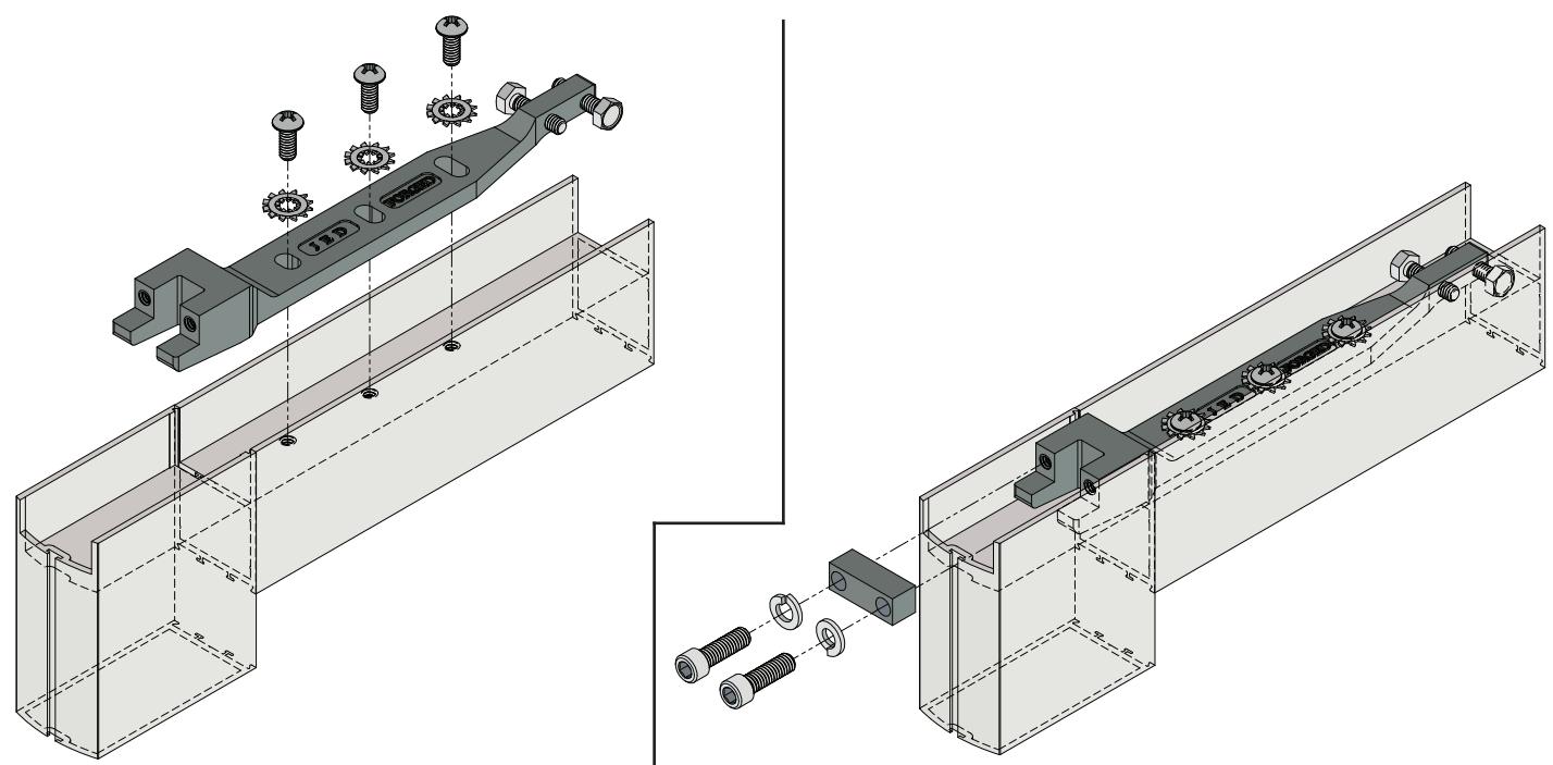
10. Secure the end-load arm to the door rail with (3) 1/4-20 x 5/8" pan head screws, lift the door onto the floor pivot and tilt onto the closer spindle.
11. Secure the clamping block to the end-load arm with (2) 5/16-18 x 1" socket head screws.
SIDE-LOAD ARM INSTALLATION
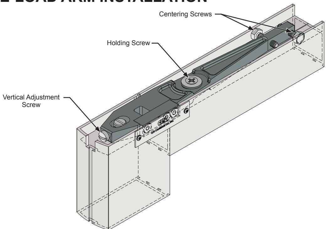
12. To center the door it must be open to 90 degrees to access the Centering Screws, each centering screw must be fully extended to the inside of the door rail by tightening one and loosening the other, to prevent the arm from spinning. NOTE: Over-expanding the centering screws can permanently bulge the door rail. Adjust the door's vertical alignment by loosining the Holding Screw, adjust the Vertical Adjustment Screw. When the door is correctly positioned, tighten the Holding Screw down firmly.
END-LOAD ARM INSTALLATION
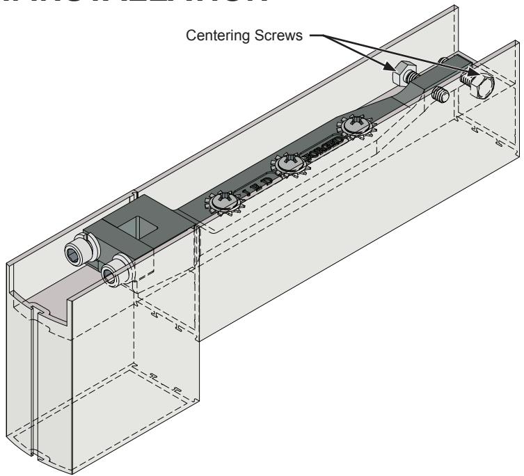
13. To center the door it must be open to 90 degrees to access the centering screws, each centering screw must be fully extended to the inside of the door rail by tightening one and loosening the other, to prevent the arm from spinning. NOTE: Over-expanding the centering screws can permanently bulge the door rail.

OFFSET ARM INSTALLATION
14. Mount the arm on spindle and secure it with 1/4-20 x 7/8" socket head cap screw.
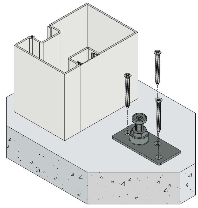
OFFSET BOTTOM PIVOT INSTALLATION
15. Secure the bottom pivot to the door rail with (4) 1/4-20 x 3/4" flat head machine screws.
16. Secure the bottom pivot to the door jamb with (4) 1/4-20 x 3/4" flat head machine screws.
SLIDE CHANNEL INSTALLATION
17. Mount the slide channel and secure it with (3) 8-32 x 3/8" flat head machine screws.
OFFSET ARM TO SLIDE CHANNEL INSTALLATION
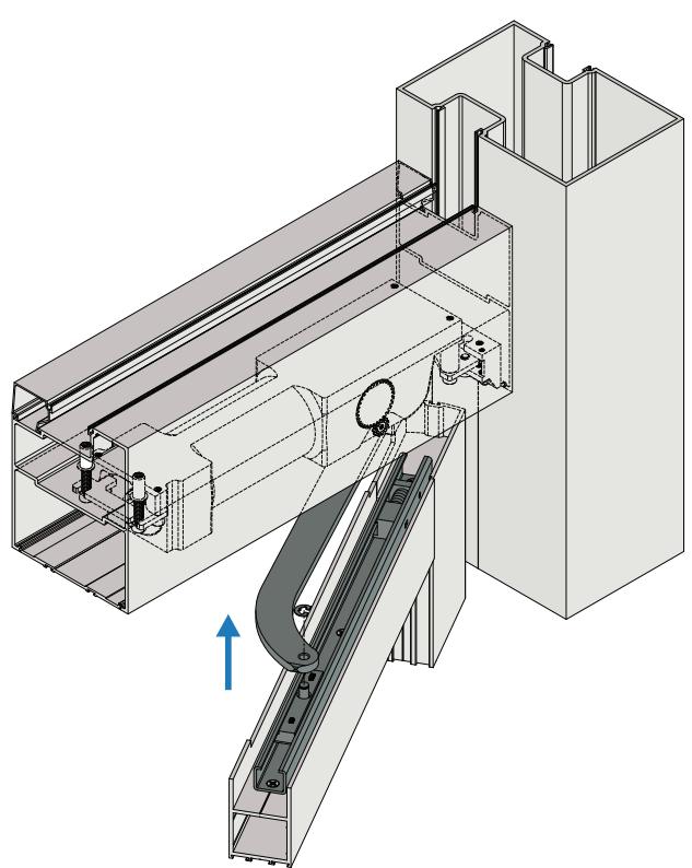
18. Lift the door onto the offset bottom pivot and swing the door in the open position and slip the arm over the slide pin and secure it with the pin retainer.
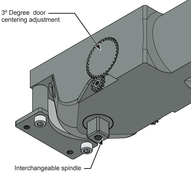
CLOSER ADJUSTMENT
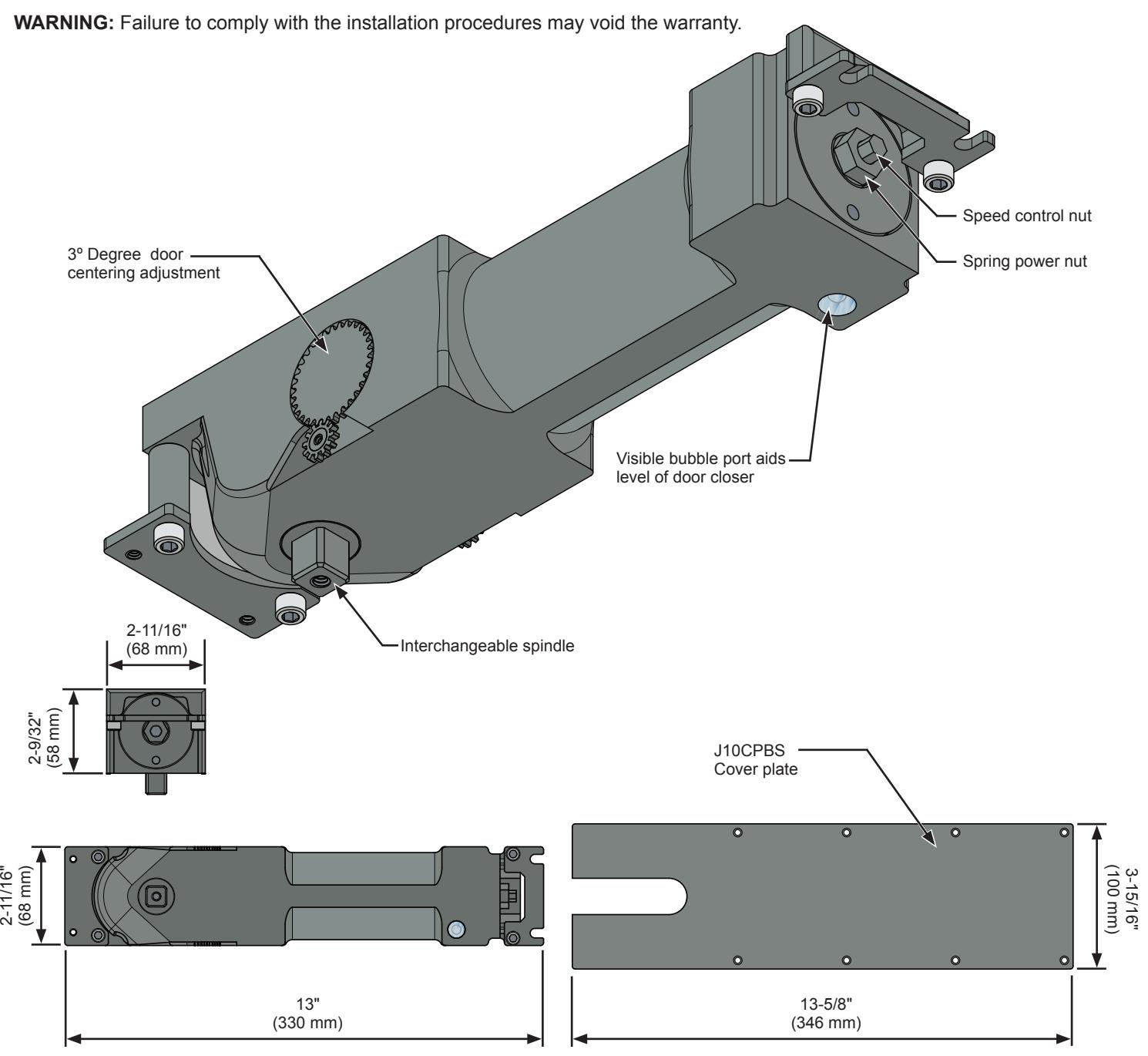
- 1. Check that the door returns to the center closed position. Adjust the center position of the door by using the Centering Adjustment Gears on either side of the closer mechanism. (See Page 03)
- 2. Adjust the speed control nut to control a smooth closing speed of approximately 5 to 7 seconds from a 90° degree open position.
- 3. The 1000 Series UOHC Closer features a spring power range of size 1-6. The Chart on the right shows the approximate amount of the full turns required to advance from '0' thought the spring power range up to size '6'. The standard factory setting is at approximately mid-range, size '3', so to increase to size '4' will require three additional full clockwise turns or to decrease to size '2', two full counter-clockwise turns.
4. Oversize doors may require an increase in the backcheck resistance. Adjust the larger hex nut clockwise to increase the power of the spring or counter-clockwise to decrease the power.
5. Attach the Dress Cover Plate when all adjustments are completed.
NOTE: Although the 1000 Series UOHC Closers feature adjustable spring power that allows these closers to be set to comply with A.D.A. specified opening forces, they may not provide adequate spring force to control and close the door due to minimized closing force, varying site conditions, and door size.
J1000 SERIES UOHC CLOSER SPRING POWER SETTINGS
Visible bubble port aids level of door closer
| APPROXIMATE TURNS FROM | ||
|---|---|---|
| -4 | 4 | 1 |
| -2 | 6 | 2 |
| FACTORY SETTING | 8 | 3 |
| +3 | 11 | 4 |
| +8 | 16 | 5 |
| +15 | 23 | 6 |
crlaurence.com | usalum.com 11
Speed control nut
Spring power nut