Isonas Fire Alarm and Life Safety Knowledge Base
Open the original PDF document
View PDF

Knowledge Base Article
Fire Alarm and Life Safety with ISONAS Powernet ™ Devices
Copyright © 2009-2016, ISONAS All rights reserved
Table of Contents
|
1: INTRODUCTION
3 |
|
|---|---|
| 2: DOOR HARDWARE3 | |
| 2.1: FAIL SECURE AND FAIL SAFE HARDWARE3 | |
|
2.1.1: Fail Safe Hardware
3 |
|
|
2.1.2: Fail Safe Hardware
4 |
|
| 3: FIRE ALARM INTEGRATION4 | |
| 3.1: CONFIGURATION #1: RELAY AT DOOR4 | |
|
3.2: CONFIGURATION #2: TRADITIONAL POWER SUPPLY
4 |
|
| 3.3: CONFIGURATION #3: ALTRONIX ENTRADA4 | |
| 4.0: ADA CONFIGURATION5 | |
| 4.1: ADA REQUIREMENTS5 | |
| Table of Figures | |
|
FIGURE 1 -
ROUNDED DOOR KNOB 3 |
|
|
FIGURE 2 -
LEVER HANDLE3 |
|
|
FIGURE 3 –
FAIL SAFE LOCK WIRING 6 |
|
|
FIGURE 4 -
FIRE ALARM INTEGRATION - RELAY AT DOOR 6 |
|
|
FIGURE 5 -
FIRE ALARM INTEGRATION - TRADITIONAL POWER SUPPLY6 |
|
|
FIGURE 6 -
FIRE ALARM INTEGRATION - ALTRONIX ENTRADA 6 |
|
|
FIGURE 7 -
ADA INTEGRATION WITH CAT DS1 BOARD 6 |
Document Version
( KBA203FireAlarmandLifeSafety.docx )
| Date of | Revision | Author | Description |
|---|---|---|---|
| Revision | |||
| 8/16/2016 | 1.0 | Jason Clement | Initial Release |
1: INTRODUCTION
This knowledge base article will review Life Safety with F™ devices, mainly Fire Alarm and doors with ADA operation. Life safety is extremely important in Access Control. The general rule of thumb should be "in an emergency people should always be able to egress out of any door easily". Edge based access control systems present a unique challenge that legacy panel based systems did not have.
This knowledge base article (KBA) is a guide to assist in the design and wiring of these systems. This guide does not over rule any local codes, ordinances or the Authority Having Jurisdiction (AHJ). The AHJ has final say on how the system should work. If there is any doubt on how a door should be configured always contact the AHJ.
2: DOOR HARDWARE
2.1: FAIL SECURE AND FAIL SAFE HARDWARE
2.1.1: Fail Safe Hardware
A fail secure lock will default to a locked state when power is removed. This is typical for electric strikes, electrified exit bars, etc. With these locks no additional egress is typically needed. A person exiting can either turn the handle or press the crash bar to exit the door.
One item to note on fail secure doors that rounded door knobs are generally discouraged (see figure 1). Lever handles are preferred as they are easier for people use and egress out of the door (see figure 2). Depending on the building occupancy it may be required to install panic exit devices (i.e. crash bars) to easily exit the doors. Please refer to the International Building Code to determine if this is needed for your project.

Figure 1 - Rounded Door Knob

Figure 2 - Lever Handle
2.1.2: Fail Safe Hardware
A fail safe lock will default to an unlocked state when power is removed. This means power must be applied to the lock in order to keep it locked. Magnetic locks are always fail safe. Electric strikes can be purchased fail safe or may have a setting on the lock to configure it fail safe. Since the lock is powered there must be a device that drops power to the lock to allow egress.
For most jurisdictions an integration to the fire alarm is required when installing fail safe locks. ISONAS recommends three different configurations for this integration. In addition to the fire alarm integration fail safes locks should have two forms of egress at the door. The first being a request to exit device, typically a motion or momentary button, and a timed exit button that works as a backup to the request to exit device. See figure 3 on page 6 for an example of this wiring.
3: FIRE ALARM INTEGRATION
3.1: CONFIGURATION #1: RELAY AT DOOR
In this configuration the fire alarm contractor will install a relay at each fail safe door. The magnetic lock power will be wired through that relay so that when the relay triggers power is cut to the lock. This ensures that when the fire alarm is active the relay will cut power to the door allowing free egress. This is the simplest method but is not always feasible. See figure 4 on page 7.
3.2: CONFIGURATION #2: TRADITIONAL POWER SUPPLY
In this configuration a power supply with a fire alarm input is used such as the Altronix AL1024ULACM. A power cable, typically 2 wire 18 gauge, is ran from the power supply to the door. This power supply will power the lock instead of power over Ethernet (PoE) or a local power supply. The fire alarm contractor installs one relay near the power supply that provides the trigger to that power supply.
When the relay is triggered during a fire alarm the power supply will drop power to the locks connected to it. Power supplies such as the Altronix recommended above are selectable by output on which locks will lose power and which will not. This an easy and centralized method for fire alarm integration that does not require many relays from the fire alarm system. It does require additional investment in cable, labor, power supplies and wiring. See figure 5 on page 8.
3.3: CONFIGURATION #3: ALTRONIX ENTRADA
In this configuration the Entrada adapters are used for fire alarm egress through the Ethernet cable. The receiver is installed in the network closet near the switch and has two ports. The first port plugs into the switch and the second port is for the Ethernet cable to the door. The transmitter is installed at the door and uses PoE or PoE+ to provide power to the reader controller and to the magnetic lock.
The receiver in the network closet has a fire alarm input and will unlock the door on fire alarm without any additional cables. Using PoE+ this allows for easy use of magnetic locks that exceed the 600ma power output of the reader controller. This solution utilizes the existing network infrastructure for the fire alarm integration. One fire alarm relay in the network closet can trigger multiple Entrada devices as each door will need a pair for integration. See figure 6 on page 9.
4.0: ADA CONFIGURATION
4.1: ADA REQUIREMENTS
Several requirements must be met for ADA operation. First the reader controller cannot be mounted more than 48" from the floor. Secondly when the door is in a LOCKED state the exterior ADA button should not unlock or open the door. Third the electric lock should unlock with the door opener starting a half second after the unlock. This prevents the latch from "sticking" and causing the door to not open. Lastly if the door is in a LOCKED state the interior ADA button should admit entry and initiate the door to open.
ISONAS recommends using a Command Access Technologies DS1 Delay/Sequencer Board. This device will provide all the controls listed above without having add timers, additional relays and complex wiring. The DS1 board has an input for the reader controller relay which will then trigger the peripheral devices with the correct timing. See figure 7 on page 10.
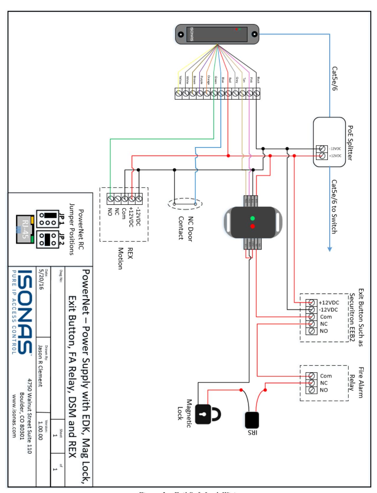
Figure 3 – Fail Safe Lock Wiring
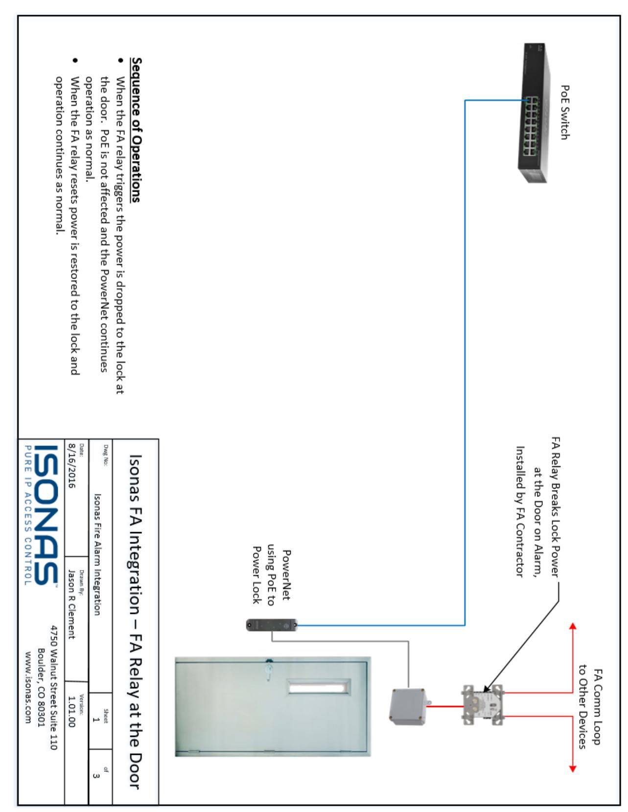
Figure 4 - Fire Alarm Integration - Relay at Door
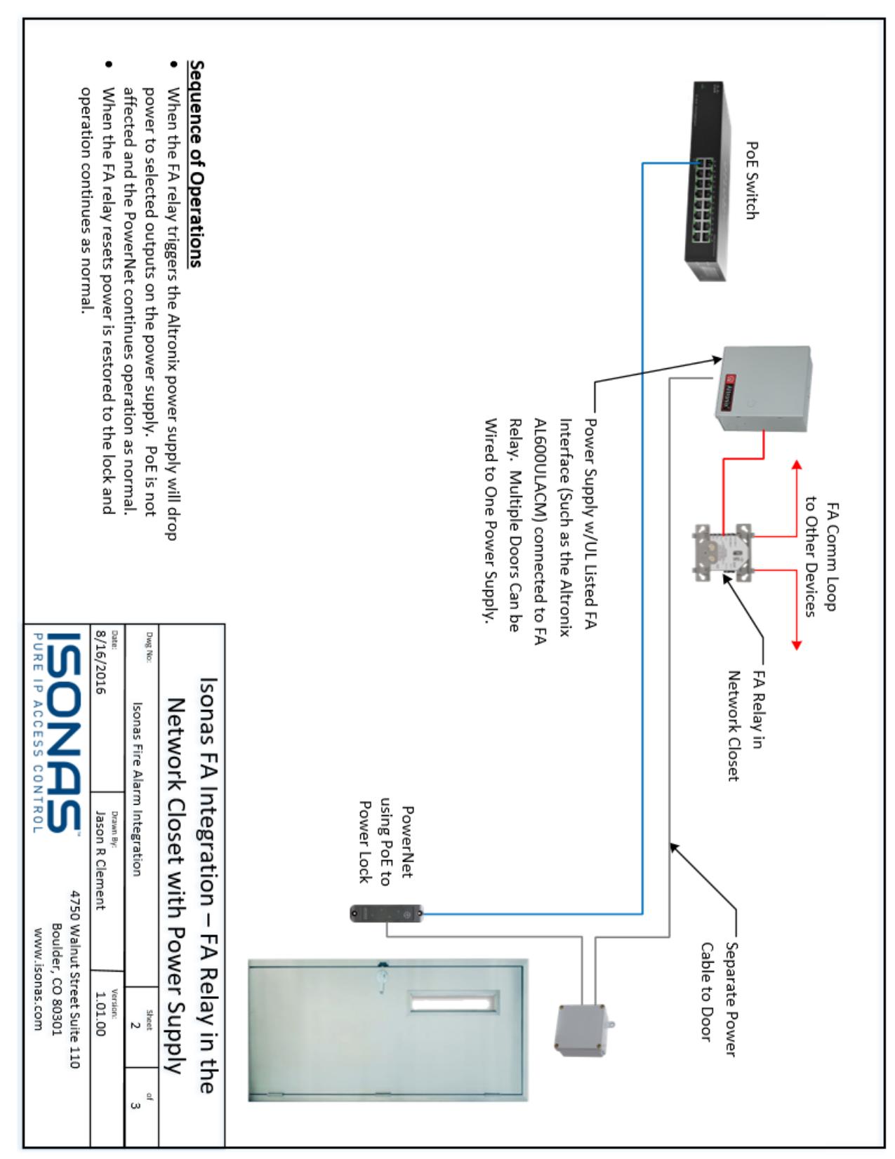
Figure 5 - Fire Alarm Integration - Traditional Power Supply
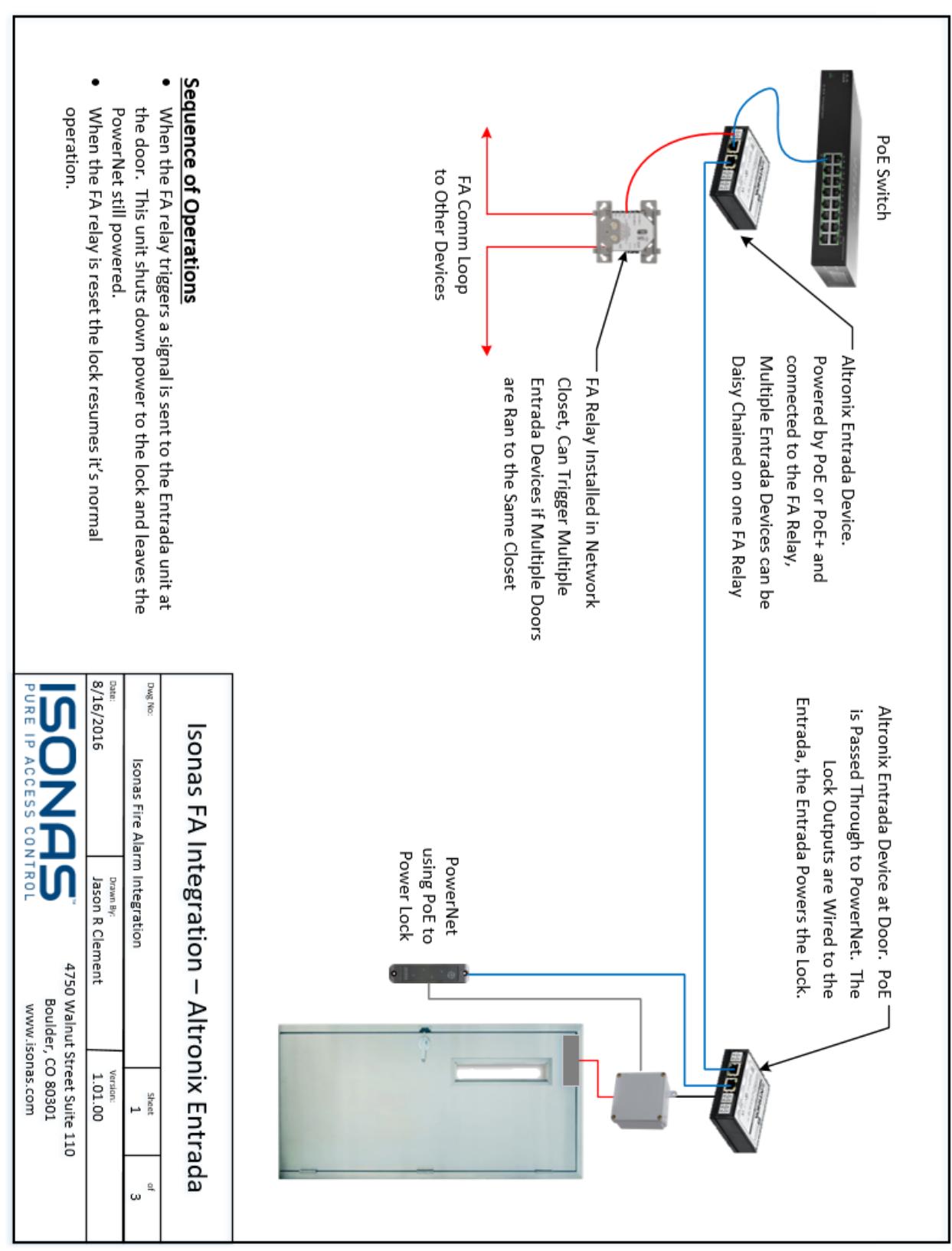
Figure 6 - Fire Alarm Integration - Altronix Entrada
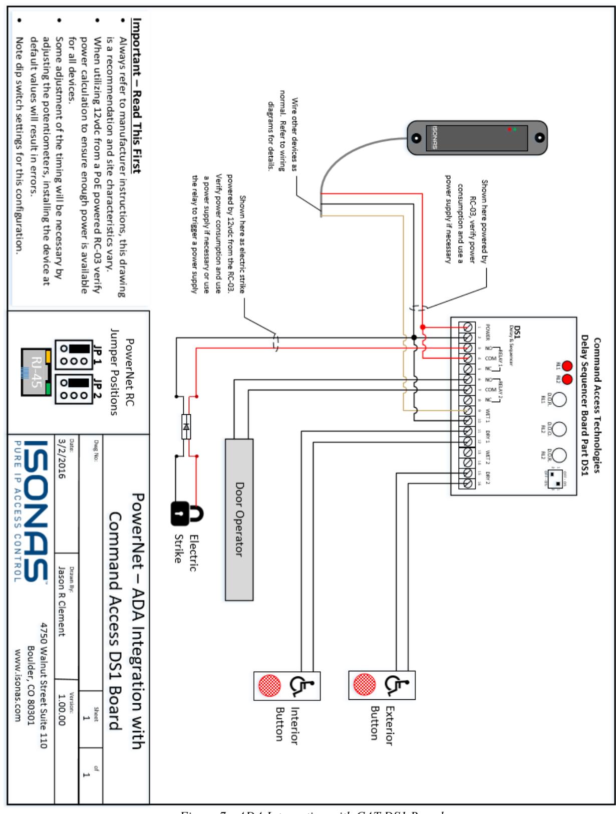
Figure 7 - ADA Integration with CAT DS1 Board
For more information:
Web: www.ISONAS.com E-mail: sales@ISONAS.com
Tel: 800-581-0083 (toll-free) or 303-567-6516 (CO)
Fax: 303-567-6991
ISONAS Headquarters:
4750 Walnut Street, Suite 110, Boulder, Colorado 80301 USA