Instructions for installing 6500 Line Single & Double Lever Pull
Open the original PDF document
View PDFInstructions for Installing 6500 Bored Locks
(See reversed Side for Installing 6500 Series Dummy Trim)
ASSA ABLOY
SARGENT
ASSA ABLOY, the global leader in door opening solutions
FOR INSTALLATION ASSISTANCE CALL SARGENT AT 1-800-727-5477 / www.sargentlock.com
A. Door Preparation
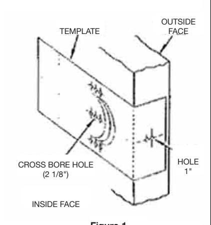
1. Place paper template (supplied) on door and mark for holes. Repeat for other side of door. (Follow instructions on paper template).
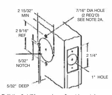
- 2. Drill the 2-1/8" cross-bore & put in notches. Then, drill the 1" hole.
- 2A. Drill 9/64" pilot holes halfway through door (Repeat for other side of door). Then, using pilot holes, drill (2) 7/16" dia. holes halfway through the door. (Repeat for other side of door.)
- 3. Mortise latch unit from 5/32" into door edge to dimensions shown.
B. Latch Installation
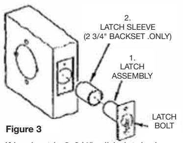
- 1. If backset is 2-3/4", slide latch sleeve (2) onto the latch assy. (1). (as shown).
- 2. Insert Latch Assy. (1) into 1" hole, making certain that latch bolt bevel faces direction of closing door. (as shown)
- 3. DO NOT secure Latch Assy. (1) until engaged with Lockbody (4), as described in Figure 6.
C. Adjustment for door thickness
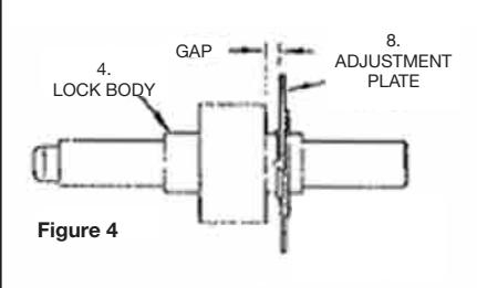
Before inserting Lockbody (4) into the door, adjust for door thickness
- 1. Screw the Adjustment Plate (6) onto the Lockbody (4).
- 3. Rotate the Plate until the required gap is
- 3/16" gap for 1-3/8" door 5/16" gap for 1-3/4" door Lock will fit in any door from 1-3/8" to 1-3/4" thickness
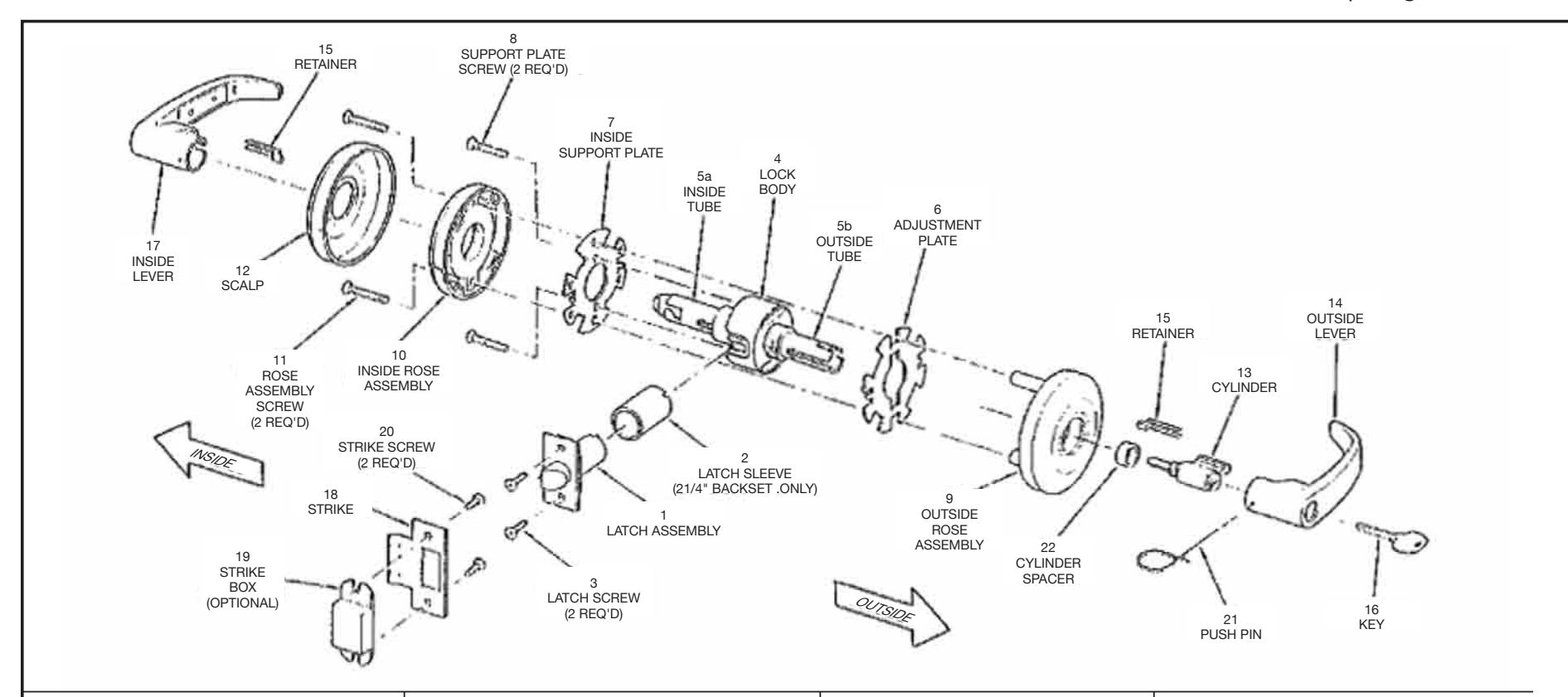
D. Installation of lockset unit
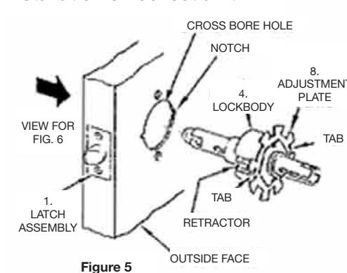
- 1. Position Lockbody (4) (as shown in fig. 5) with retractor facing the Latch Assembly (1), and the tabs of the Adjustment Plate (6) lined up with the notches on the door.
- 2. Slide the Lockbody (4) into the cross-bore hole from the outside position.
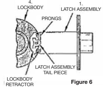
- 3. Lockbody (4) must engage the prongs of the Latch Assy. (1) as
- 4. The retractor of the Lockbody (4) must engage the tailpiece of the latch Assy. (1). Be sure the door is open when installing lockset unit if a guarded-latch unit is used.
- 5. Now you can tightly secure the Latch Assy. (1) with Screws (3) supplied.
E. Securing the lockset unit to the door
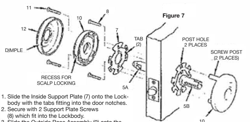
- Slide the Outside Rose Assembly (9) onto the outside Tube (5B) with the Screw Posts entering the post holes.
- Slide the Inside Rose Assembly (10) onto the Inside Tube (5A). Line up the Inside Rose Assembly holes with the Outside Rose Assembly Screw Posts and secure with the 2 R Assembly Screws (11)
- Slip the Scalp (12) onto the Inside Rose Assembly (10) aligning the dimples with recesses in the Rose and turn clockwise to lock.
F. Installation of levers
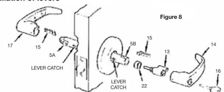
- 1. Slide Cylinder Spacer (22) onto the Cylinder (13). Open end of the Spacer fits over the Cylinder Barrel. (See Figure 8).
- 2. Insert the Cylinder (13) into the Outside Lever (14) and secure with Retainer (15).
- 3. Slip the Outside Lever (14) onto the Outside Tube (5B) as far as possible. Insert the Key (16) and turn approx. 90° clockwise. Push the lever again until the lever catch is engaged, securing the lever. (Lever Catch my need to be depressed, using Push Pin (21).)
- 4. Insert the remaining Retainer (15) into the Inside Lever (17) and slide the Lever onto the Inside Tube (5A). Push the lever until the lever catch is engaged. (Lever Catch may need to be depressed using push pin (21).
G. Installing Strike
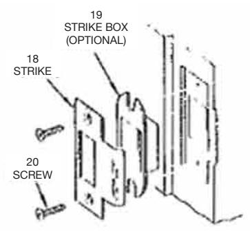
1. When Strike Box (19) is not used (optional), recess in door jamb must be deep enough to allow latch bolt to extend to its full free length.
Cylinder Removal
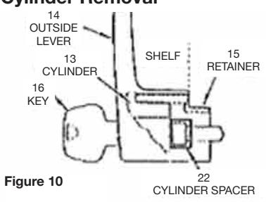
- 1. To remove Outside Lever (14), insert Key (16) and turn approx. 90 ° clockwise. Insert Push Pin (21) into the hole on lever to depress lever catch. Slide the Lever from the Tube (5).
- 2. Using standard pliers, pull out the retainer (15).
- 3. Remove Key (16), Cylinder (13), and Cylinder Spacer (22) from the Lever.
- 4. When replacing Cylinder (13), secure by pressing Retainer (15) till flush with shelf.
Instructions for Installing 6500 Line
SARGENT
ASSA ABLOY
FOR INSTALLATION ASSISTANCE CALL SARGENT AT 1-800-727-5477 / www.sargentlock.com
ASSA ABLOY, the global leader in door opening solutions
SINGLE LEVER PULL
DOUBLE LEVER PULL
A. Door Preparation
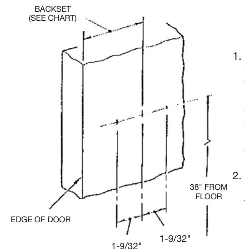
BACKSET 2-3/4" STANDARD 2-3/8"
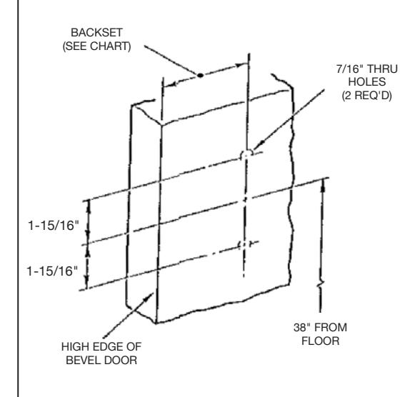
- 1. Measure backset from door edge and 38" up from the floor and make a mark. Put a square on edge of door and line up with mark. Then draw a horizontal line 1-1/4" long on both sides of mark.
- 2. Backset 1-9/32" left and right from the mark on the horizontal line mark
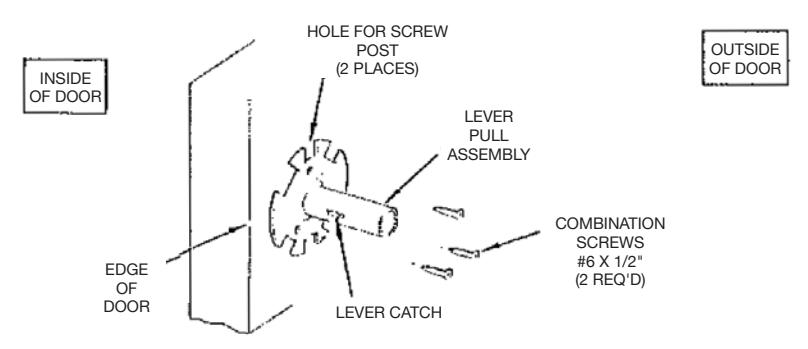
B. Attaching lever pull assembly
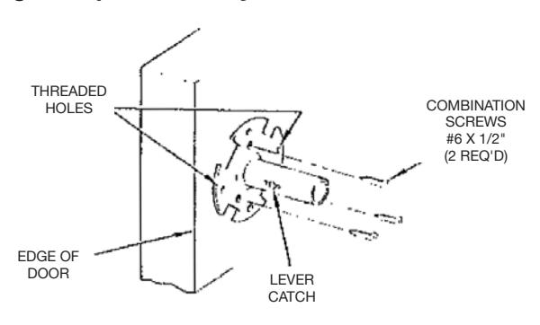
1. Place lever pull assembly onto door so that the two marks 1-9/32" from the center are seen through the two threaded holes. Make sure plate is orientated on door correctly (note: lever catch is always facing towards edge of door). Attach assembly to door with (3) #6 x 1/2" combination screws. Tighten securely.
C. Attaching rose
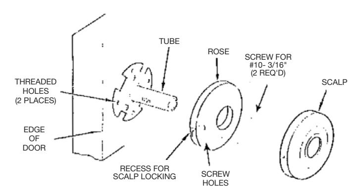
- 1. Slide rose onto tube making certain screw holes line up with the threaded holes on the lever pull assembly
- 2. Secure rose with two #10-32 x 3/16" screws
D. Install Lever
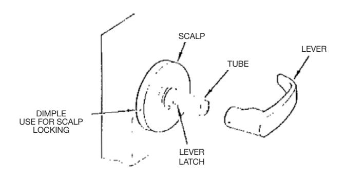
- 1. Place scalp onto rose aligning dimples with recesses in the rose (see above) and turn clockwise to lock.
- 2. Slide lever onto tube. Make certain lever catch on tube is engaged in levers.
A. Door Preparation
BACKSET 2-3/4 " STANDARD 2-3/8"
- 1. Measure backset from door edge and 38" up from the floor and make a mark. Put a square on edge of door and line up with mark. Then draw a horizontal line 1-1/4" long on both sides of mark.
- 2. Backset 1-5/16": up and down from the mark on the horizontal line mark locations. Drill 1/8" pilot holes halfway through door. Using pilot holes drill two 7/16" holes slightly more than halfway through.
- 3. Repeat steps 1 and 2 on opposite side
B. Attaching lever pull assembly
1. Place lever pull assembly onto door as shown above. Make sure plate is oriented on door correctly (note: lever catch is always facing towards edge of door).
2. Attach assembly to door with (2) #6 x 1/2" wood screws, tighten securely. Repeat procedure on opposite side of door.
C. Attaching roses
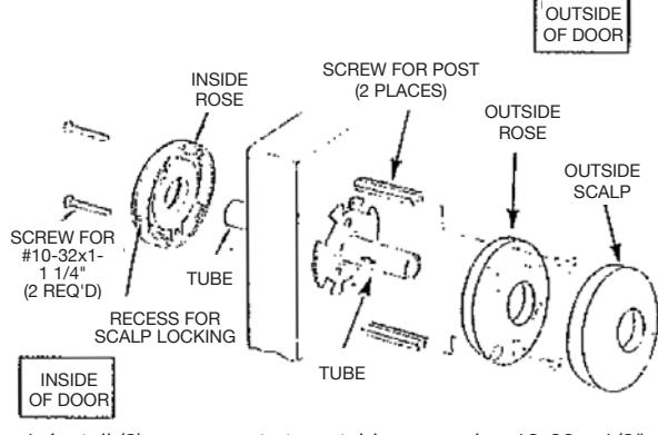
- 1. Install (2) screw posts to outside rose using 10-32 x 1/2" screws supplied.
- 2. Slide outside rose onto tube making certain screw posts line up with the holes in the door.
- 3. Slide inside rose onto tube and secure both roses with two #10-32 x 1-1-1/4" screws.
D. Install Lever
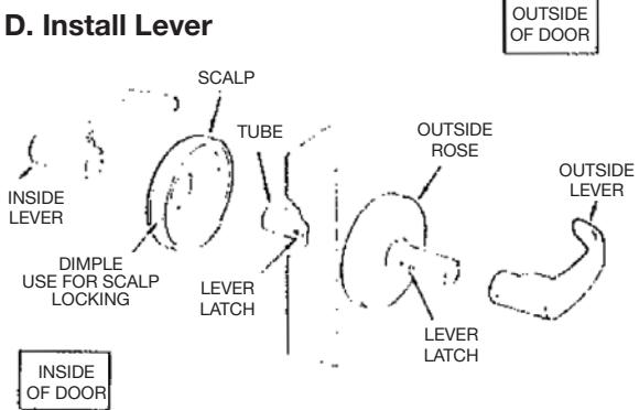
- 1. Place scalp onto inside rose aligning dimples with recesses in the inside rose (see above) and turn clockwise to lock.
- 2. Slide inside/outside levers onto tube. Make certain lever catch on tube is engaged in levers.
For 64U94-2 function only
Fits ANSI A115.2
Mount trim in the same manner as 65u94 except omit step "a" attach blank front with (2) #8-32x 3/4" Phillips head screws.
To Install Levers
- 1. Push lever & cylinder onto tube as far as it will go
- 2. Turn key counter clockwise as far as it will go
Caution: At this time check to see if key can be removed from cylinder. if not, remove lever and rotate key 180°. Push lever and cylinder onto tube as far as it will go.
3. Turn key 45° clockwise. Push lever onto tube. Make certain lever catch on tube is engaged in lever.
To Remove Levers
- 1. Turn key counter clockwise as far as it will go.
- 2. Turn key 45° clockwise.
- 3. Depress lever catch through hole
- 4. Slide lever from the tube.
Copyright © 2012, Sargent Manufacturing Company, an ASSA ABLOY Group company. All rights reserved. Reproduction in whole or in part without the express written permission of Sargent Manufacturing Company is prohibited.