Instructions for installing 470 Series Deadlock
Open the original PDF document
View PDFSARGENT ® INSTALLATION INSTRUCTIONS FOR 470 LINE DEADBOLT
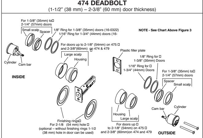
Type Door Spacer Rings 474 1-3/8" 16-0322 (special thickness 1/8") 474 1-3/4" 16-0322 (1/16") 474 2" No spacer 474 2-3/8" No spacer, no small scalp 475 1-3/8" 16-0322 (special thickness .275") 475 1-3/4" 16-0322 (.063") Figure 3
1. CHANGING BACKSET
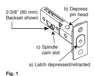
The latch is set for 2-3/8" (60 mm) backset. To change this backset dimension follow these steps: Figure 1&2
a) Make sure the latch is fully depressed. b) Depress the pin (b) and at the same time pull the spindle cam (c) fully to the opposite side. Ensure that the pin (b) returns to the correct position.
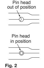
IMPORTANT: If you have pulled the spindle cam slot (c) fully to the left and the pin has not entered in the new pin hole, introduce a sharp object in the hole shown in fig. 2 and adjust the retracting cam such that the pin is released and secured in its new position.
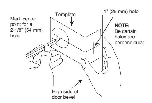
2. MARK HOLES
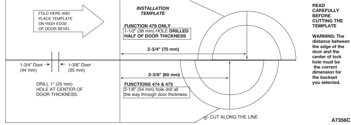
a) Position the installation template (attached) over the edge of door. Latch hole:
b) Mark the 1" (25 mm) latch hole. This hole should be made at the center of the edge of the door.
Lock hole:
c) First, select 2-3/8" (60 mm) or 2-3/4" (70 mm) backset and then mark the center of the hole.
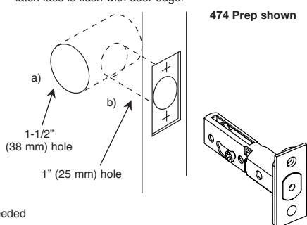
3. PREP THE DOOR
Lock hole:
479 function only:
Bore a 1-1/2" (38 mm) hole starting from inside of door and drilling only half of door thickness.
475 2"-2/16" No spacer, no small scalp
474 and 475 function only:
Bore a 1-1/2" (38 mm) or 2-1/8" (54 mm) hole from both sides of door.
Latch hole:
All functions:
- a) Bore a 1" (25 mm) hole straight into center of door edge.
- b) Chisel 1/8" (3 mm) recessed area in edge of door until latch face is flush with door edge.
4. DEADBOLT INSTALLATION
- a) IMPORTANT NOTE: Confirm spindle cam position on the latch is in the correct backset position, 2-3/8" (60 mm) or 2-3/4" (70 mm) as needed per door prep. Also, be sure the spindle cam is oriented on the bottom of the latch assembly as it is being installed in the door.
- b) Install the latch in the door with the bolt depressed and/or retracted and attach with appropriate screws.
- c) Install outside assembly (cylinder without holes) first. The cam bar must be in the vertical position (with latchbolt in the retracted position) before inserting into spindle cam slot, or lock could malfunction.
474 DEADBOLT
Note: See exploded view for parts required for various door thicknesses.
- d) Turn the key of the outside assembly (already installed) so the latchbolt is fully extended.
- e) Install the inside assembly (with holes) inserting the cam bar in vertical position into the latch spindle cam.
- f) Attach both units with installation screws. Do not fully tighten.
- g) Check the operation of the deadbolt before closing the door. If the latch operation is not correct, slightly shift the two assemblies until it functions properly. Tighten the screws for the two assemblies and the latchbolt.
475 DEADBOLT
- d) Once the outside assembly is installed (Step C Above),
- place the thumbturn assembly onto the cam bar. e) Attach the two assemblies with installation screws. Check the operation before closing the door, and if necessary, repeat Step D4.
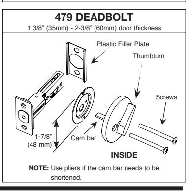
479 DEADBOLT
- d) Position mounting plate in door hole and align three holes with those in deadbolt. Secure with two screws on outer edge of plate.
- e) Insert cam bar of thumbturn vertical or horizontal into spindle cam slot. If thumbturn cannot lay flat against door face, then remove from door and shorten cam bar with pliers at break line.
- f) Place cam bar in spindle cam slot. Align screw holes and fasten with two screws.
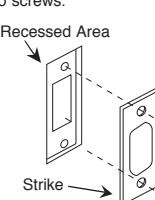
5. INSTALL STRIKE
Mark vertical line and height line on jamb exactly opposite center point of latch hole. Clean out hole and install strike box. Make sure strike is flush with frame by recessing area.
475 DEADBOLT 1-3/8" (35mm) - 2-2/16" (54mm) door thickness OUTSIDE INSIDE Cam bar Thumbturn Screws Plastic Filler Plate See 474 for proper use of rings and spacers.