Instructions for installing 2700 Series Vertical Rod Exit Device
Open the original PDF document
View PDF2700 Series Surface Vertical Rod
For additional information or assistance, contact SARGENT at 800-727-5477 or www.sargentlock.com
SARGENT
ASSA ABLOY
ASSA ABLOY, the global leader in door opening solutions
Installation Instructions
2700 Series Surface Vertical Rod
For additional information or assistance, contact SARGENT at 800-727-5477 or www.sargentlock.com
To Change Hand
All 2700 Series exit devices are handed and reversible. The 2700 is assembled for a left hand reverse bevel door at the factory.
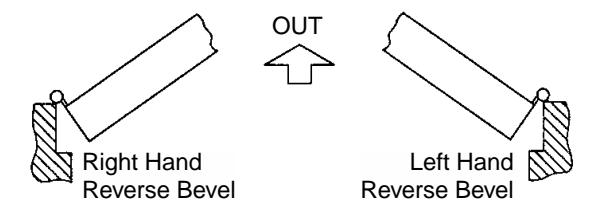
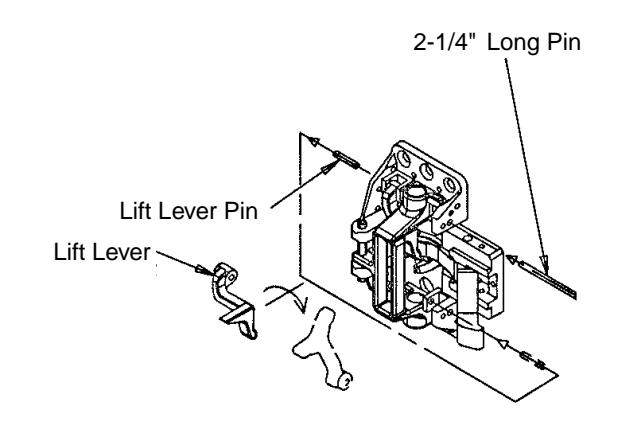
To Change Hand:
- 1. Use 2-1/4" long pin (supplied in screw pack) to knock out left lever pin.
- 2. Remove lift lever and reassemble other end of chassis.
Mark Door
Before starting, door should be fitted and hung. Check box label for hand and size of the exit device.
Surface of the door where exit device is to be applied must be flush. Clear away any raised projections to allow exit device to rest on flat surface of the door.
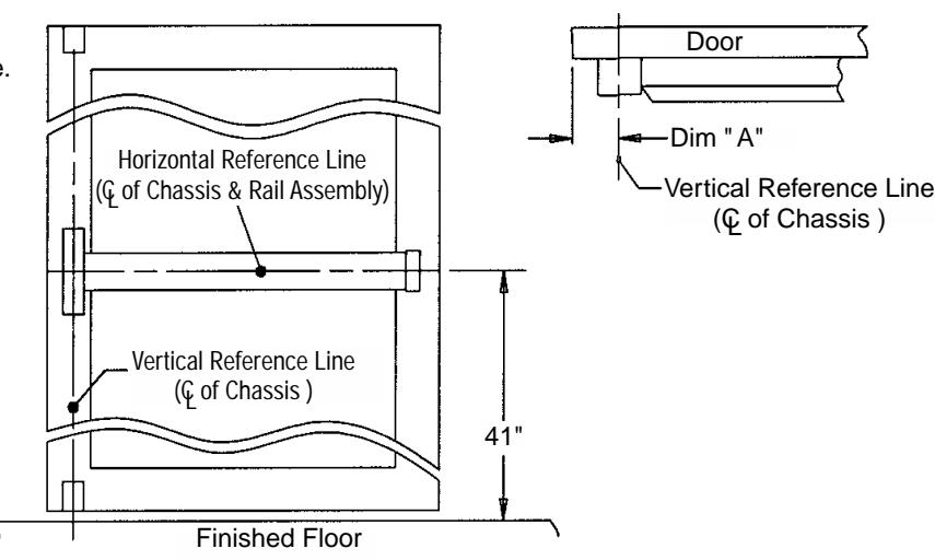
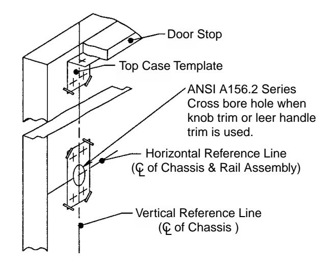
- 1. Using door template, mark vertical and horizontal reference lines on the door.
- 2. Determine Dimension " A" : If lock stile is 4-1/2" wide or wider, Dimension A = 2-3/4"
If lock stile is less than 4-1/2" wide, Dimension A = 1/2 of the exposed width of lock stile (when door is closed against stop).

2700 Series Surface Vertical Rod
For additional information or assistance, contact SARGENT at 800-727-5477 or www.sargentlock.com
Door Preparation
Tape template onto the inside of the door along reference lines with supplied tape.
If door already has door prep (161 Cut-out), ANSI or has 2-1/8" Dia hole at 2-3/4" backset, position template over exiting hole then spot and drill holes.
Apply Hardware
For Lever Trim Applications: See separate instruction sheet, packed with trim.
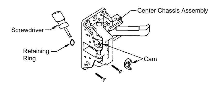
For Exit Applications ONLY
Using retaining ring pliers (not shown) or screwdriver, remove retaining ring from cam. Remove and discard cam from the center chassis assembly for flush mounting. Attach chassis with (4) #10 wood or machine screws.
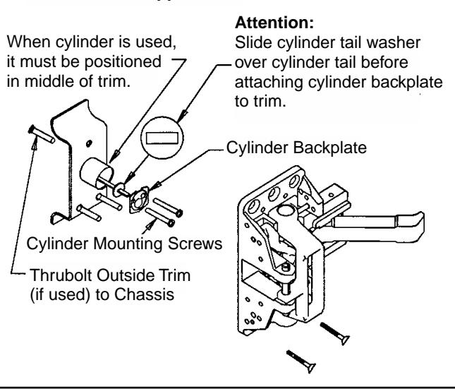
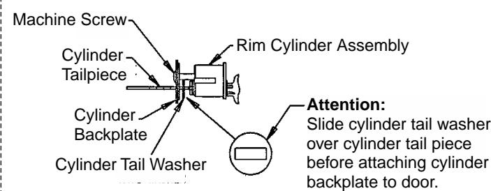
For 28-K- Application HTB For Rim Cylinder Application ONLY
Attention:
Use standard shims for center chassis mounting.
Attention:
Mounting cylinder to door before mounting chassis.
Continued
2700 Series Surface Vertical Rod
For additional information or assistance, contact SARGENT at 800-727-5477 or www.sargentlock.com
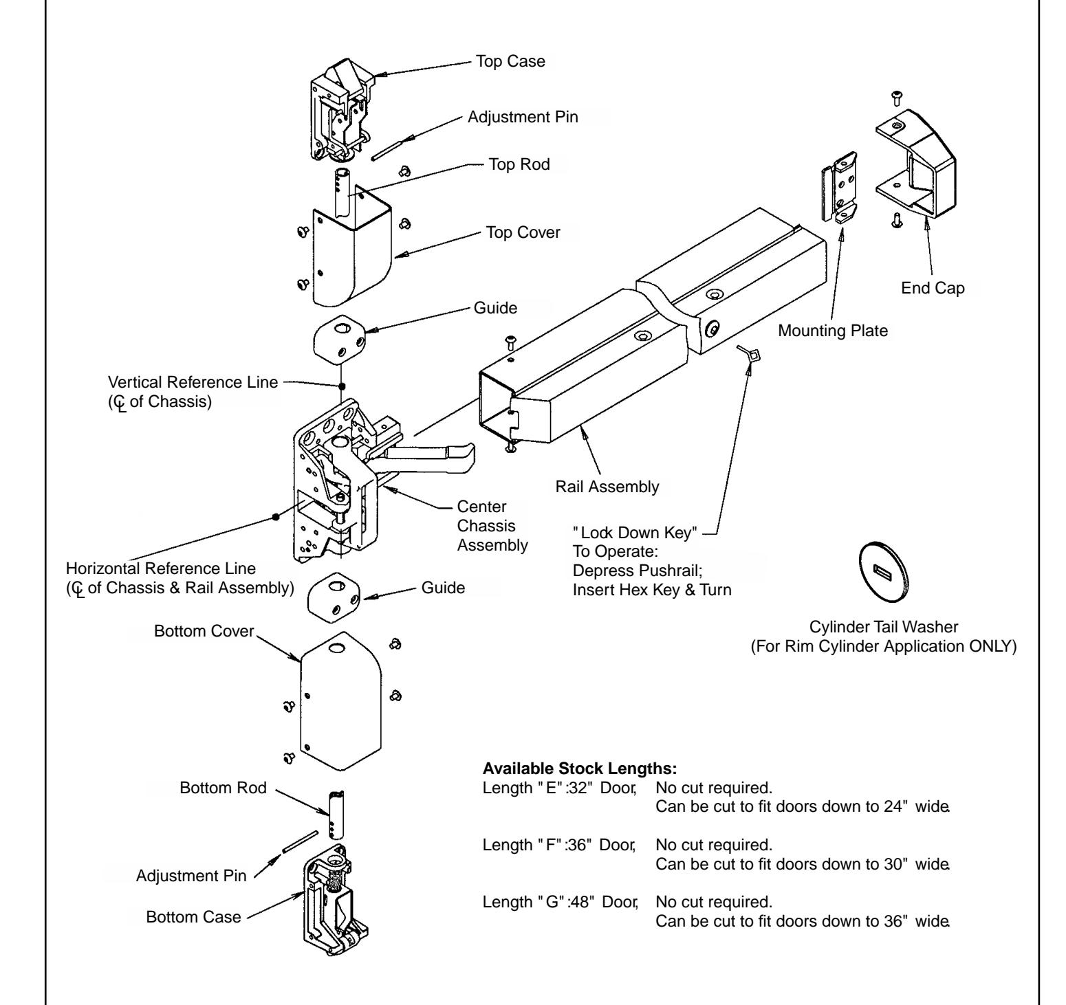
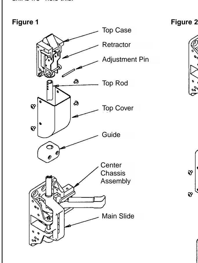
Install Top & Bottom Cases
- 1. Mount top strike according to location marked when marking door with template. Use #10 steel screws provided.
- 2. Ensure push rail is not locked down. Screw top rod into main slide.
- 3. Slide guide and cover onto top rod and assemble retractor and middle hole in rod. (See Figure 1.) Adjust so that top case mounting holes line up with location marked when marking door with template.
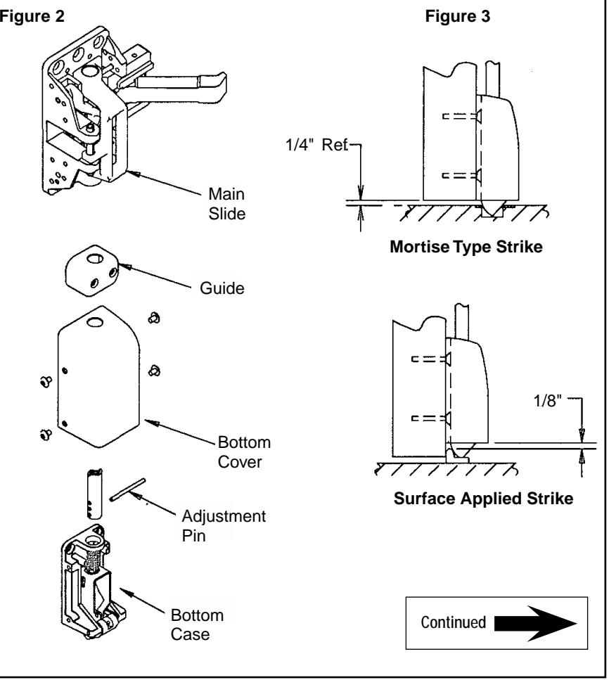
- 4. Mount bottom case in same manner as top case. (See Figure 2.) Refer to Figure 3 for various strike applications.
- 5. Secure guides.
NOTE: If shorter rods are required, cut to length and drill Ø1/8" hole thru.

2700 Series Surface Vertical Rod
For additional information or assistance, contact SARGENT at 800-727-5477 or www.sargentlock.com
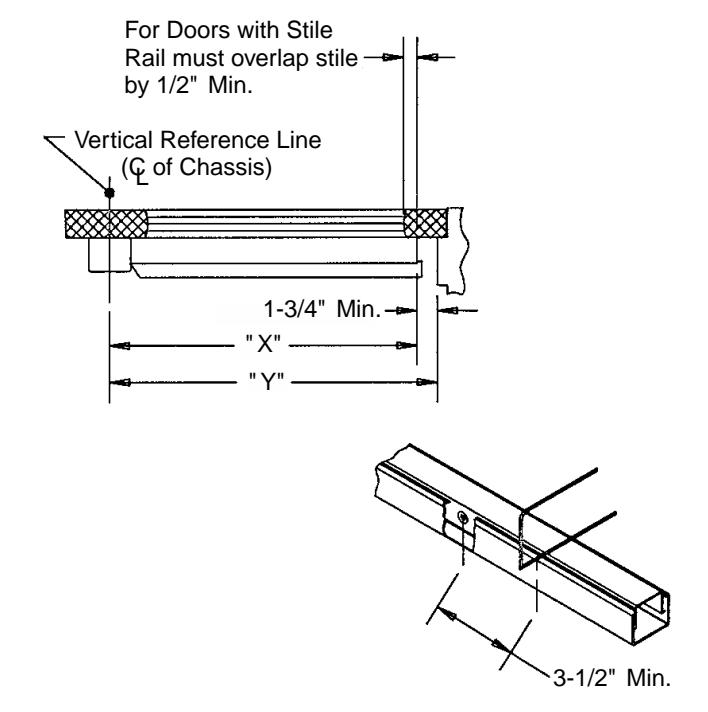
Install Rail Assembly
Check box label. If cutting is not required proceed to Step B. If cutting is required, continue with Step A.
-
A
- 1. Determine cutoff dimension " X" by subtracting 1-3/4" from dimension " Y" .Mark cutoff point on mounting rail.
- 2. Hold down push rail. Cut off and deburr.
CAUTION: Do not cut closer than 3-1/2" from connecting arm pivot in push rail.
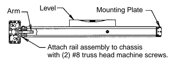
-
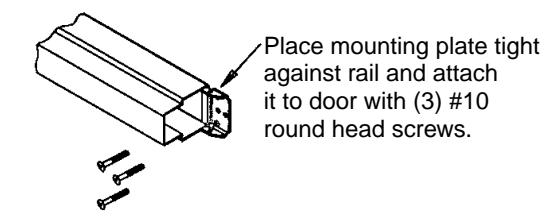
1. Depress arm into rail opening and slide rail onto chassis. Level rail and fasten mounting plate.
B
- 2. Place mounting plate tight against rail and attach it to door with (3) #10 round head screws.
Continued
2700 Series Surface Vertical Rod
For additional information or assistance, contact SARGENT at 800-727-5477 or www.sargentlock.com
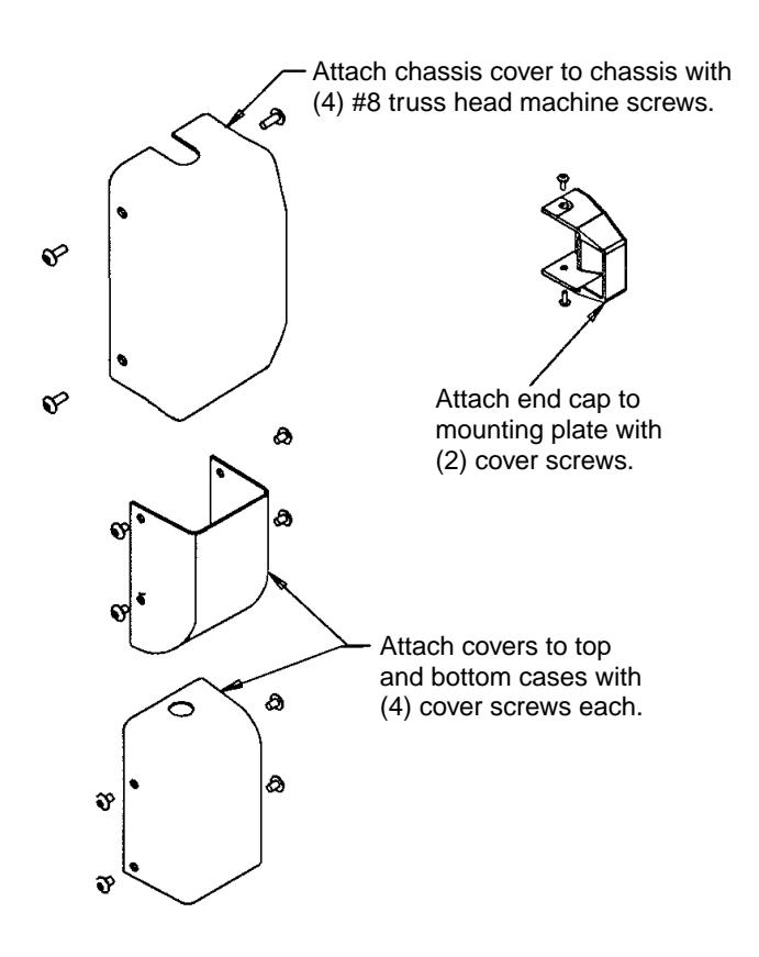
Apply Covers
Product Support Tel 800.727.5477 • www.sargentlock.com
Sargent Manufacturing Company, an Group company. ASSA ABLOY
Copyright ©2015 Sargent Manufacturing Co. All rights reserved. Reproduction in whole or in part without the express written permission of Sargent Manufacturing Co. is prohibited. These materials are protected under U.S. copyright laws. All contents current at time of publication. Sargent Manufacturing Company reserves the right to change availability of any item in this document, its design, construction, and/or its materials.
A6187M 7-15