Instructions for Rekeying the 65-6300 Large Format Interchangeable (Removable Core) Assembly
Open the original PDF document
View PDFInstallation Instructions

6300, 11-6300 & 10-6300
LFIC (Removable Core) Cylinders

This product can expose you to lead which is known to the state of California to cause cancer and birth defects or other reproductive harm. For more information go to www. P65warnings.ca.gov.
1-800-727-5477 • www.sargentlock.com
Copyright © 2009, 2011, 2016, 2022, SARGENT Manufacturing Company. All rights reserved. Reproduction in whole or in part without the express written permission of SARGENT Manufacturing Company is prohibited. Patent pending and/or patent www.assaabloydss.com/patents.

Attention Installer: Improper installation may result in damage to the product and void the factory warranty.
6300, 11-6300, & 10-6300
LFIC (Removable Core) Cylinder
Installation Instructions


1 Installation Notes
The 6300 series LFIC (Removable Core) uses a control key whose bittings match the Top Master Key of the key system in positions 1, 2, 5 and 6. The control bittings in positions 3 and 4 are selected from the Key Bitting Array of the master key system.
This method signifi cantly reduces the bittings available in the Key Bitting Array of any Top Master Key. Increasing the levels in the master keying system and cross keying also has a signifi cant impact on the yield of keys at each selected level.
The chamber stack value for the 6300 series LFIC (removable core) is normally calculated by using a stack value of 15 in positions 1, 2, 5, and 6. This is the total value of the bottom pins, master splits and driver pins that would be required to pin the core (based on the keying levels).
In chambers 3 and 4 of the 6300 series LFIC (removable core), the stack value is 20. This is done to allow the control key to achieve a shear line in chambers 3 and 4 of the control sleeve.

Important : Cylinders master keyed at the factory use hollow drivers and SARGENT recommends their continued use. Hollow drivers must be used in chambers 3 and 4. A different spring is used in conjunction with the hollow drivers.
These special drivers and springs are included in a special pinning kit 437 RC. The drivers and springs can also be ordered individually. The machined or hollow end of the hollow driver faces towards the spring.
- 65-6300 or 1 bitted cylinders are supplied for fi eld keying and are provided with 2 key blanks
- 65-6300 cylinders are shipped without pins and springs
- 1 bitted cylinders supplied for fi eld keying have pins loaded only in chambers 3 and 4
- 111111 bitted cylinders utilize a control key cut 113511
6300, 11-6300, & 10-6300
LFIC (Removable Core) Cylinder
Installation Instructions

2
Installation Instructions
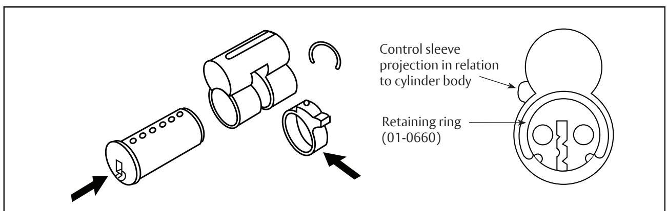
Remove the retaining ring, then remove the barrel from the cylinder body and sleeve or load from the top using the Top Loading Kit (P/N 436-1). a
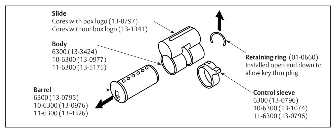
With sleeve positioned correctly in cylinder body (as shown above), load barrel and cylinder body. Use the template on page 4 to determine pinning. b
Note : The SARGENT rekeying kit 437 RC contains the hollow drivers and springs that must be used in chambers 3 and 4 for factory keyed cores prior to January 2009.
Finish assembling by installing the retaining ring to barrel. The barrel is designed to hold the ring in position. c
Important : The retaining ring must clear keyway.
A6409M 08/22
3
Template
SARGENT ASSA ABLOY
The following is an example showing how to select the pin segments for each chamber of the SARGENT 6300 series LFIC (removable core). Use this as a template for calculating the correct pin loads.
| 1 | List of Operating Keys |
Sample
KEY SYMBOLS |
mpl
TTI |
i | ||||||||||||||||
|---|---|---|---|---|---|---|---|---|---|---|---|---|---|---|---|---|---|---|---|---|
| List Day Changes/MK's GM's etc | . GM "A" | 4 | 9 | 4 | 1 | 6 | 0 | |_ | |_ | _|_ | _| | _| | _| | _| | | _| | _| | _| | _|| | ||
| Do Not list bitting of | MK "AA" | 4 | 9 | 2 | 3 | 6 | 0 | |_ | _|_ | _|_ | _| | _ | _| | _| | | _| | _| | _| | |||
| the Control key in this area. | CK "AA1" | 2 | 1 | 2 | 3 | 2 | 2 | |_ | |_ | _| | _| | _| | _| | _| | | _|_ | _| | _| | |||
| 2 | Calculate Bottom Pins and Master Splits Find correct size for Bottom and Master Splits from operating key's list | |||||||||||||||||||
| (a)***** BOTTOM PINS ******* (Smallest number in each chamber) (b)***** MASTER SPLITS ****** (Difference in smallest and largest number in each chamber) | 2 | 1 |
Sam
l
2 |
ple
1 |
2 | 2 | l | _| | _| | .| | | | |||||||||
| 2 | 8 | 2 | 2 | 4 | 8 | _| | _| | | | | | |||||||||||
| 3 | Calculate Value of Contr | 4 | 9 | 6 | 5 | 6 | 0 | 1 | _L | L | L | L | | | | |||||||
| (3.1) A number 8 appears on this line in positions 3 and 4 | - | - | 8 | 8 | - | - | | - | | - | | 8 | | 8 | | - | | |||||||||
|
(3.2) Insert bitting of positions 3 and 4 of control key.
and add to number 8's in positions 3 and 4 |
+6 | +5 | |- | |||||||||||||||||
| 3.3 CONTROL PIN FACTOR | = | 14 | 13 | | - | |- | | |||||||||||||||
| (3.4) Subtract largest number from list of operating ke |
er in positions 3 and 4
eys from control pin factor |
-4 | -3 | | | | - | _| | | | - | | ||||||||||||
| (c)***** CONTROL SPLIT | ****** | = | = | 10 | 10 | | | - | |||||||||||||
| 4 | Calculate Top or Driver I | Pin (Total Stack Value) | 15 | 15 | 20 | 20 | 15 | 15 | 15 | 15 | | 20 | 20 | |15 | | 15 | | ||||||
|
4 | 9 | 14 | 13 | 6 | 10 | | | _| | _| | | | .| | | | ||||||||
| (d)(4.3) Enter values on this line. DRIVER SPLITS (Master Sp. | ) | 11 | 6 | 6 | 7 | 9 | 5 | _| | _| | | | _|| | |||||||||
| 5 | Pinning Assembly Matrix Example of pinning matrix for above key bittings. | |||||||||||||||||||
| Transfer Values labeled | (d) Driver Splits | 11 | 6 | 6 | 7 | 9 | 5 | |||||||||||||
| (a), (b), (c), (d) from items | (c) Control Splits | - | - | 10 | 10 | - | - | _| | - | | |||||||||||
| 2, 3, and 4 above. | (b) Master Splits | 2 | 8 | 2 | 2 | 4 | 8 | _| | _ | _| | _|| | |||||||||
| (a) Bottom Pins | 2 | 1 | 2 | 1 | 2 | 2 | _| | |||||||||||||
|
Stack To
Limits |
otal | - | 15 | 15 | 20 | 20 | 15 | 15 | _| | _| | | | |||||||||