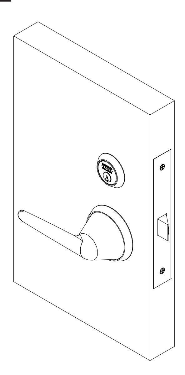
Instructions for Installing 8200 Mortise Lock with BHL Trim
Open the original PDF document
View PDF

BHL Trim
For Mortise Locks
8200 Series

This product can expose you to lead which is known to the state of California to cause cancer and birth defects or other reproductive harm. For more information go to www.P65warnings.ca.gov.
BHL Trim
8200 Series
Installation Instructions

| TOC | Table of Contents | |
|---|---|---|
| 1 | Tools Required 2 | |
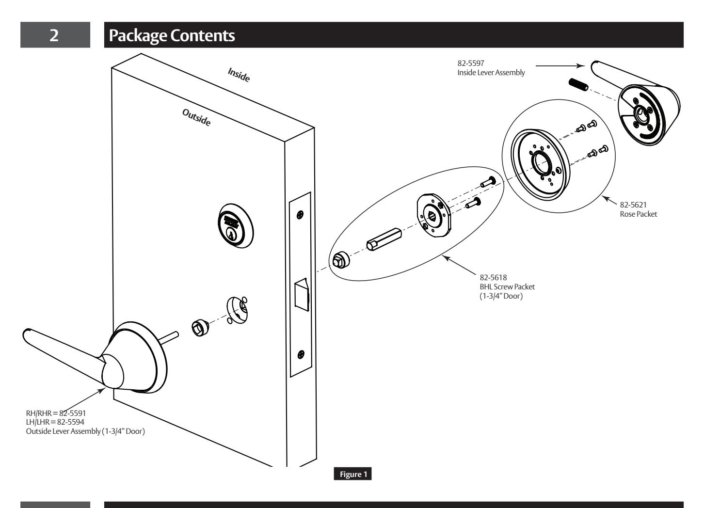
| 2 | Package Contents 3 | |
| 3 | Lock Handing 3 | |
| 4 | Change Lock Function 4 | |
| 5 | Rose Handing 6 | |
| 6 | Door Preparation 6 | |
| 7 | BHL Trim Installation 8 | |
| 8 | Installation 9 | |
| a | Install Adapter Clutch 9 | |
| b | Verify Bushing Is Tight 9 | |
| c | Install Outside Trim 9 | |
| d | Install Inside Rose/Adapter Plate | 10 |
| e | Install Inside BHL Rose Assembly | 10 |
| f | Install Inside Lever Assembly | 10 |
| 9 | Outside Lever Rehanding (Optional) | 11 |
| a | Assemble Outside Adapter Plate and Rose | 11 |
| b | Install Outside Lever Assembly | 11 |
Attention Installer
Please read these instructions carefully to prevent missing important steps.
Notes
- Improper installation may result in damage to lock and void factory warranty.
- Other product brand names may be trademarks or registered trademarks of their respective owners and are mentioned for reference only.
1 Tools Required
- Phillips Screwdriver (# 2)
- Torx Tamper Resistant Driver (T-20)
- Torx Tamper Resistant Driver (T-10)
- Hex Key Driver 5/64"

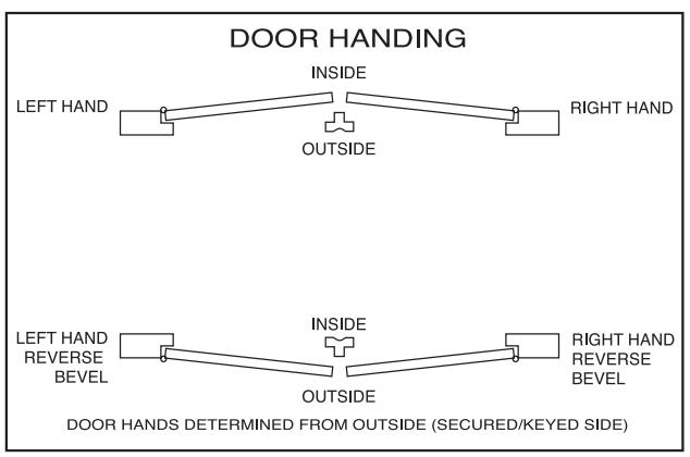
3 Lock Handing
NOTE:
Red surface of locking piece must face Secure side of door.
To rotate locking piece:
- 1. Position lockbody with red surface of locking piece visible.
- 2. Insert blade type screwdriver into locking piece slot to rotate locking piece.
- 3. Push locking piece toward back of lockbody and rotate 180° until RED surface shows on opposite side.
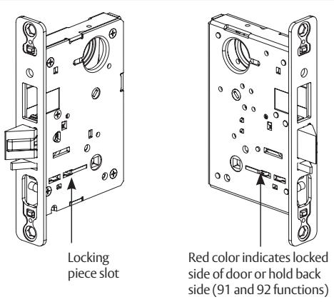
Figure 2
h

h
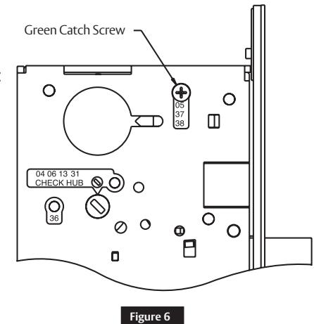
3 Lock Handing (cont.)
For 04, 06, 13 and 31 Functions:
A. Remove green catch screw.
- B. Rotate hub to 45° position.
- C. Rotate locking piece for required hand.
- D. Face red surface to locked side of door.
- E. Rotate hub to original 45° position (as shown on lockcase).
- F. Reinstall green catch screw.
Spade Shaped Slot
Figure 3
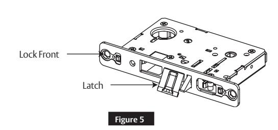
NOTE:
- Beveled surface of latch must face strike.
- Deadlatch is self adjusting.
To change hand of latch:
- 1. insert screwdriver blade into the spade shaped slot.
- 2. Rotate screwdriver 90° to push latch out until back of latch clears lock front. Rotate latch 180°. Latch will re-enter lockbody.

Latch cannot be unscrewed.
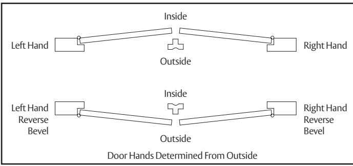
Figure 4
4 Change Lock Function
How to change function of lock:
-
Green catch screw must be located in following three (3) locations as designated on lock case to create desired function:
- 1. 05, 37 & 38 functions
- 2. 04, 06, 13 & 31 functions
- 3. 36 function
NOTE:
When moving green catch screw to 04, 06, 13 & 31 functions, hub position must be at 45° as shown on lockcase (Figure 6 ).
1-800-727-5477 • www.sargentlock.com

44 Change Lock Function (cont.)
Items needed to create each of the following functions:
| Function |
Outside
Lever |
Inside
Lever |
Trim One
Side Kit |
Outside
Cylinder |
Inside
Cylinder |
Thumb
turn |
|
|---|---|---|---|---|---|---|---|
|
04 (F07) -
Store Room Closet Lock |
X | X | X | ||||
|
05 (F04) -
Office or Entry Lock |
X | X | X | X** | |||
|
06 - Store room or
Service Lock |
X | X | X | ||||
|
13 (D31) -
Communicating or Exit Lock |
X | X | |||||
| 31 - Utility Lock | X | X | X | ||||
| 36 - Closet Lock | X | X | X | ||||
|
37 (F05) -
Classroom Lock |
X | X | X | ||||
|
38 (F32) -
Classroom Security Intruder Latchbolt Lock |
X | X | X | X | |||
#41 Cylinder is standard for both single & double cylinder functions for 1-3/4" thick door.
NOTE:
Trim-one-side functions always require an inside trim assembly which can be used on the inside or outside of the door (to order Trim one-side kit (for all trim except PT or FE) order part # 82-4611.
** 130 KB thumb turn is used with rose trim only. Escutcheon trims requiring thumb turns must be preassembled at factory.

5 Rose Handing
Review following figures that illustrate left and right roses. (Figure 7)
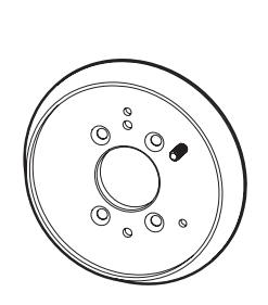
LH/LHR Outside or RH/RHR Inside
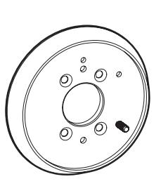
RH/RHR Outside or LH/LHR Inside
Figure 7
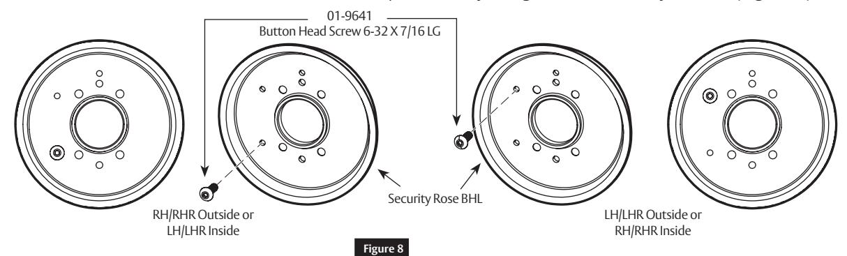
Install button head screw into each rose. Use a 5/64" hex key to tighten screw firmly to rose. (Figure 8 )
6 Door Preparation
Important:
Be sure to hand the lockbody before installing.
- 1. Insert mortise lock into door and fully tighten 1" lock mounting
- with two (2) wood screws and two (2) machine screws. (Figure 9 )
-
2. Turn-piece functions only:
- Insert turn-piece door marker spindle into lockbody on inside of door.
NOTE:
Use blade side of door marker spindle. (Figure 10 )
-
3. Turn-piece functions only:
- Slide turn-piece door marker over spindle.
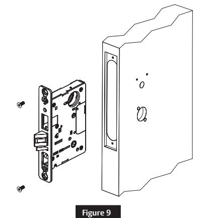
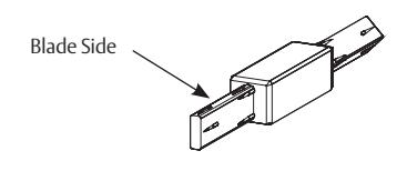
Figure 10

6 Door Preparation (cont.)
-
4. Turn-piece functions only:
- Mark three holes for turn-piece. (Figure 11 )
-
5. Coin-turn functions only:
- Insert turn-piece marker spindle into lockbody on outside of door.
NOTE:
Use blade side of door marker spindle. (Figure 10 )
-
6. Coin-turn functions only:
- Slide turn-piece door marker template over spindle.
-
7. Coin-turn functions only:
- Mark two holes for coin-turn. (Figure 12 )
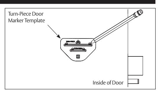

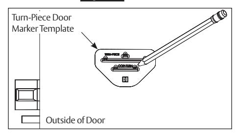
Figure 12
- 8. Remove lockbody from door.
-
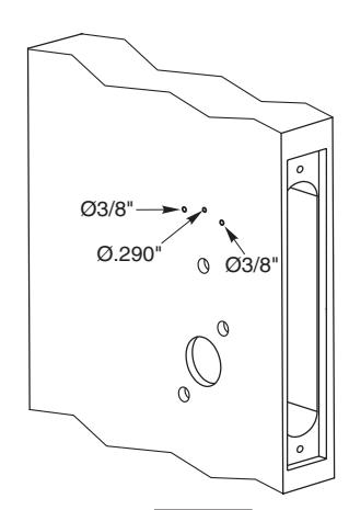
9. Turn-piece functions only:
- Drill one middle hole (.290") And two outer holes (3/8") halfway through door. (Figure 13 )
10. Coin-turn functions only: drill two holes (1/8") halfway through door. (Figure 14 )
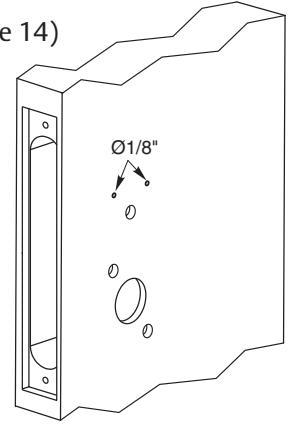
Figure 13
Figure 14

6 Door Preparation (cont.)
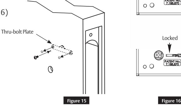
-
11. Turn-piece functions only: install turn-piece thru-bolt plate using truss head screw. (Leave screw slightly loose.) (
Figure 15)
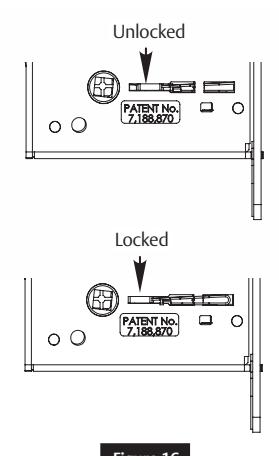
- 12. Insert mortise lockbody into door and loosely tighten 1" lock mounting combination screws.
NOTE:
Make sure lock is unlocked. ( Figure 16 )
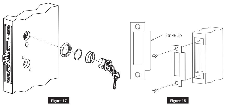
7 BHL Trim Installation
1. Install strike using 3/4" strike mounting screws.
NOTE:
Strike must be oriented with strike lip towards pull side of door. (Figure 10)
-
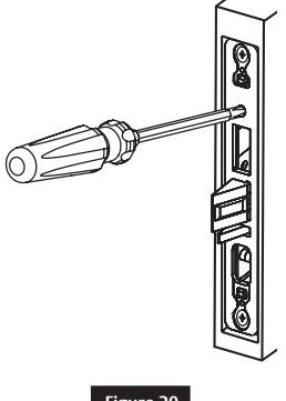
2. Cylinder functions only:
- Slide cylinder(s) through spring, spacer and collar, threading into lockbody until cylinder face is flush with collar. (Figure 11)
NOTE:
Pull key slightly out of cylinder to help thread into lockbody.
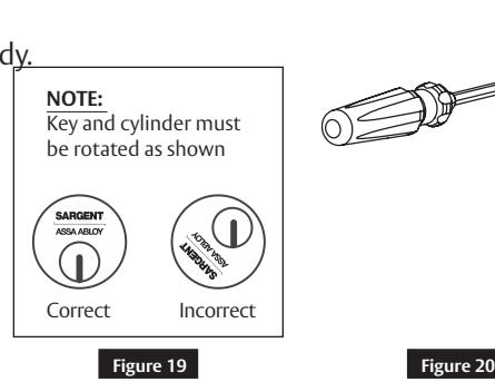
NOTE:
Cylinder must be oriented correctly. (Figure 12)
-
3. Cylinder functions only:
- Tighten cylinder set screw. (Figure 13)
- 4. Fully tighten lock mounting screws.

8 Installation
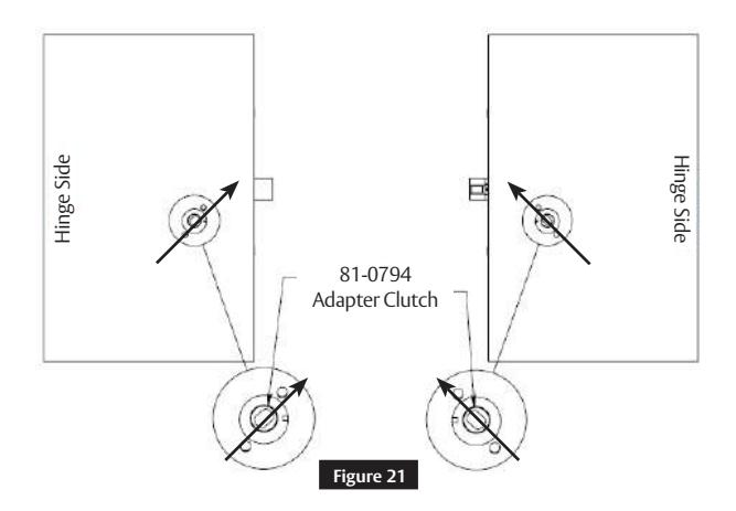
a Install Adapter Clutch
Install adapter clutch into mortise lock hub. (Figure 21)
Note
Adapter clutch is oriented toward latchbolt as shown.
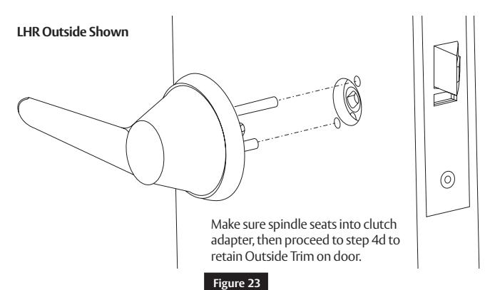
b Verify Bushing Is Tight
- Insert spindle into bushing; ensure that spindle is inserted no more than ¾" deep.
- Use spindle to rotate bushing clockwise into outside lever hole.
- Fully tighten bushing, then unthread bushing just enough to allow spindle to be inserted into lever, keeping bushing as tight as possible.
- Once assembled, spindle orientation should be as shown. (Figure 23 )
c Install Outside Trim
1-800-727-5477 • www.sargentlock.com

8 Installation (cont.)
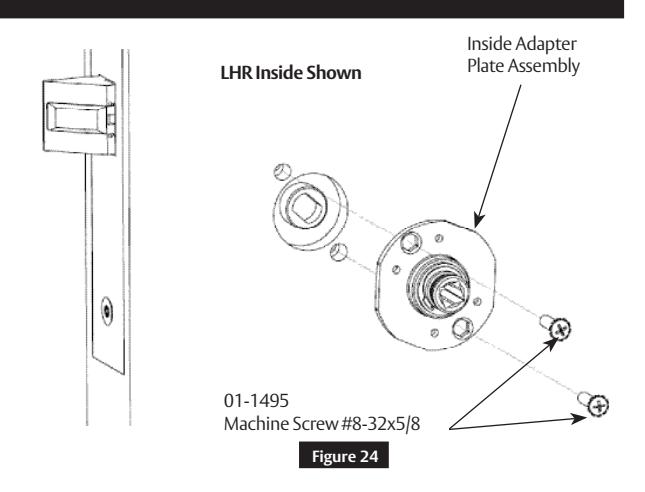
d Install Inside Rose/Adapter Plate
Install inside adapter plate assembly using two (2) machine screws. (Figure 24 )
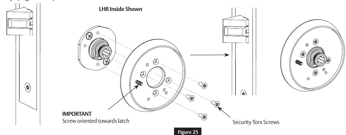
e Install Inside BHL Rose Assembly
Attach inside rose assembly to inside adapter plate using four (4) security Torx screws. Tighten screws evenly. ( Figure 25)
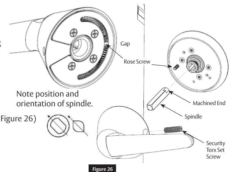
f Install Inside Lever Assembly
- Install inside spindle. (Figure 26 )
- Install inside BHL lever assembly to inside adapter plate assembly using security Torx set screw.
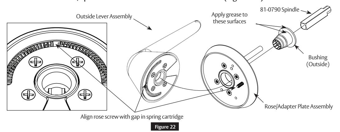
IMPORTANT
- Line up rose screw with gap on spring cartridge.
- Make sure machined end of spindle seats into clutch adapter before assembling lever onto rose. ( Figure 26)
Notes
Inside of LHR shown.
1-800-727-5477 • www.sargentlock.com

9 Outside Lever Rehanding (Optional)
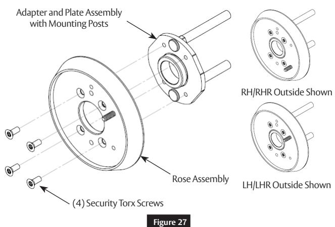
a Assemble Outside Adapter Plate and Rose
- Insert two (2) mounting posts into adapter plate. (Figure 27)
- Install rose using four (4) security Torx screws.
Note
Tighten screws evenly.
b Install Outside Lever Assembly
- Insert spindle into bushing; ensure that spindle is inserted no more than ¾" deep.
- Use spindle to rotate bushing clockwise into outside lever hole.
- Fully tighten bushing, then unthread bushing just enough to allow spindle to be inserted into lever, keeping bushing as tight as possible.
- Once assembled, spindle orientation should be as shown. (Figure 28 )
Note
Longer spindle used on outside.
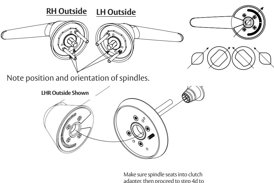
adapter, then proceed to step 4 d to retain Outside Trim on door.
Figure 28
A8131F 08/19 1-800-727-5477 • www.sargentlock.com

SARGENT Manufacturing Company 100 Sargent Drive New Haven, CT 06511 USA 800-727-5477 www.sargentlock.com
Founded in the early 1800s, SARGENT® is a market leader in locksets, cylinders, door closers, exit devices, electro-mechanical products and access control systems for new construction, renovation, and replacement applications. The company's customer base includes commercial construction, institutional, and industrial markets.