Instructions for Installing 351 Series Door Closers with OP (Double Lever Arm) & OTP (Track-Type Arm)
Open the original PDF document
View PDF351 DOOR CLOSER WITH DOUBLE LEVER ARM (OP) INSTALLATION INSTRUCTIONS
Strength Adjustable From Size 1 Thru 6
CAUTION: FAILURE TO INSTALL OR ADJUST PROPERLY MAY RESULT IN INJURY OR DAMAGE Auxiliary door stop required
FOR ASSISTANCE, CALL SARGENT AT 1-800-727-5477 or www.sargentlock.com
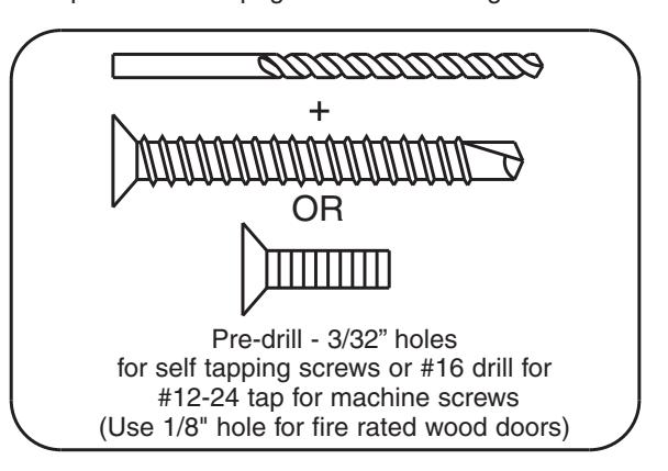
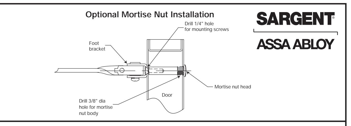
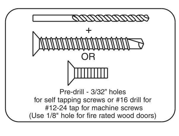
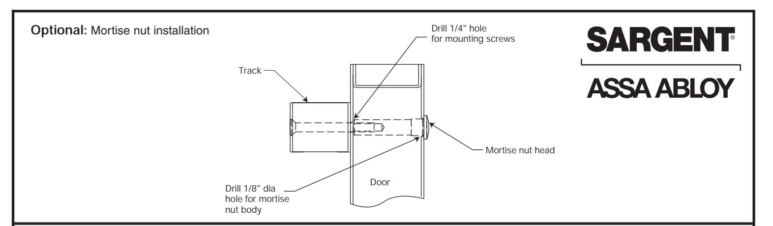
Step 1: Use template on page 3 to drill and tap door and wall for 12-24 machine screws or predrill when using self tapping screws provided. See page 2 for when using mortise nuts
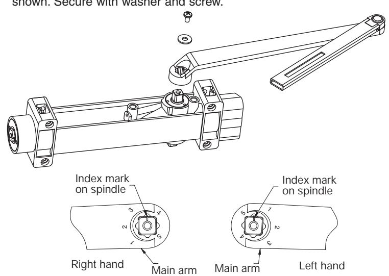
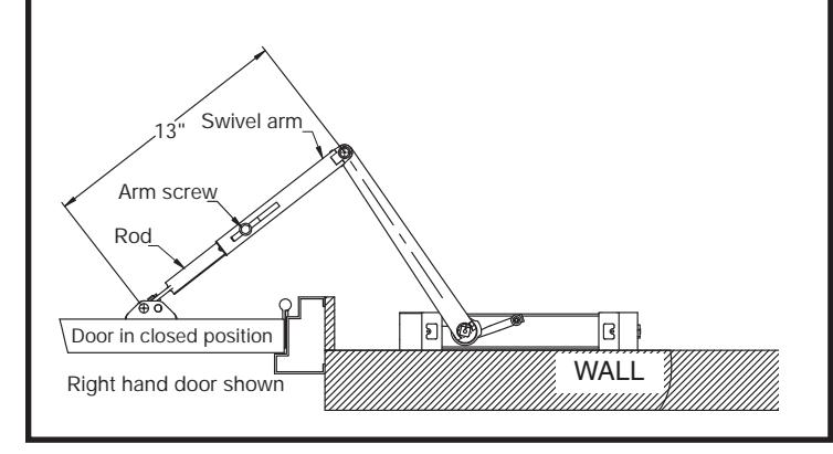
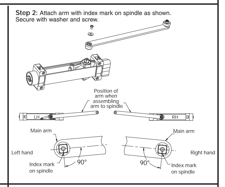
Step 2: Attach arm with index mark on spindle as shown. Secure with washer and screw.
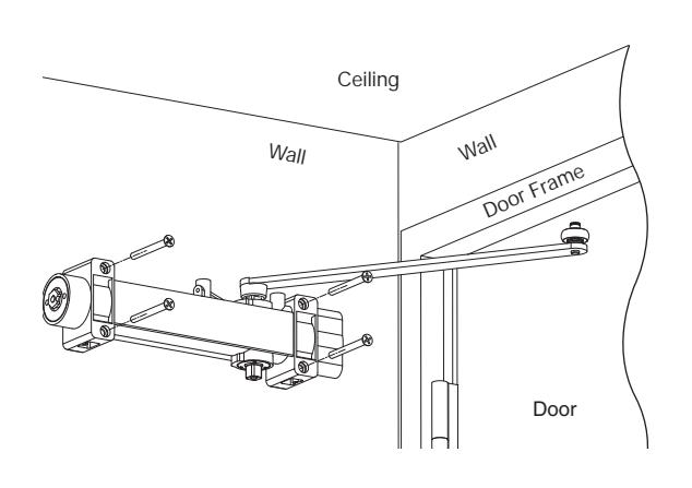
Step 3: Secure door closer to the wall using screws provided with spring power adjustment nut facing away from hinge.
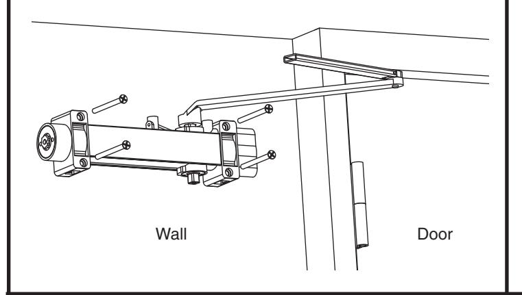
Step 4: Secure foot bracket to door using screw provided.
Step 5: Insert rod end into swivel arm and adjust length as shown. Then tighten arm screw.
Wall Door
Copyright © 2005, 2008, Sargent Manufacturing Company, an ASSA ABLOY Group company. All rights reserved. Reproduction in whole or in part without the express written permission of Sargent Manufacturing Company is prohibited.
1
A7816A
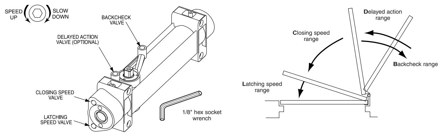
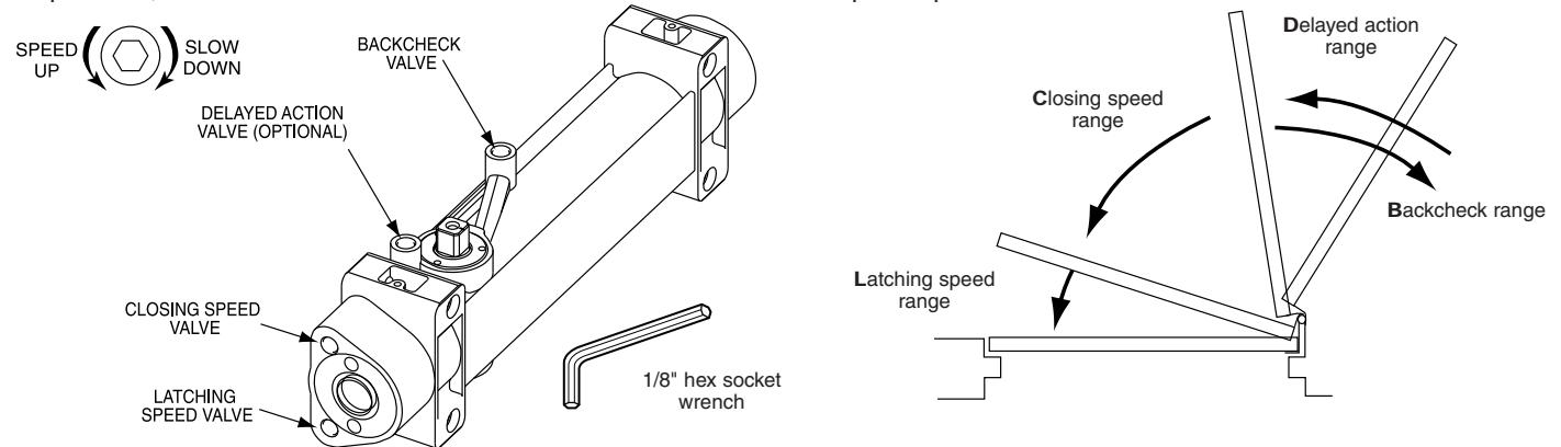
Adjusting Closing Speeds
Closing and latching speeds:
Turn valves clockwise to slow down or counterclockwise to speed up door movement.
Backcheck:
Turn valve clockwise to increase or counterclockwise to decrease.
CAUTION: SET VALVE FOR SLIGHT CUSHIONING EFFECT. CLOSER CAN BE DAMAGED IF THE CHECKING ACTION IS TOO ABRUPT. NEVER USE THE BACKCHECK AS A DOOR STOP. ALWAYS USE A DOOR STOP TO STOP THE DOOR.
Delayed action feature (optional feature):
When provided, turn valve clockwise to slow down or counterclockwise to speed up door movement.
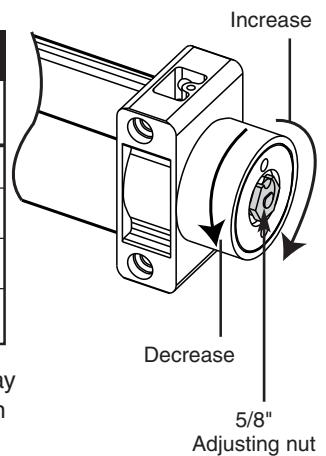
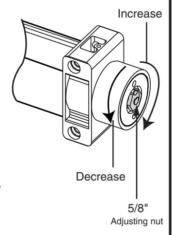
Adjusting Closing Power
- Increase closing force to achieve proper door latching.
- Decrease closing force if the door is difficult to open.
INSTALLATION GUIDE
| Number of Turns of Spring Power Adjusting Nut | ||
|---|---|---|
|
Door Width
(Inches) |
Exterior Doors | Interior Doors |
| 24-30 | TURN nut 1-3 | TURN nut 1-3 |
| 30-36 | FACTORY SET | FACTORY SET |
| 36-42 | TURN nut 1-4 | TURN nut 1-3 |
| 42-48 | TURN nut 7-9 | TURN nut 4-6 |
Adjusting door to close due to high draft conditions may exceed ADA standards. Consult local ordinances when
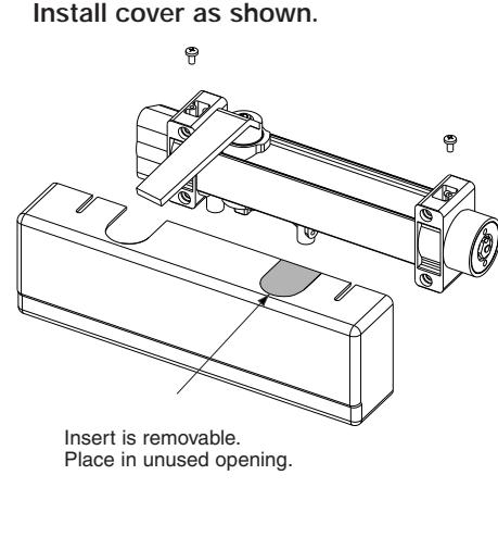
Install cover as shown.
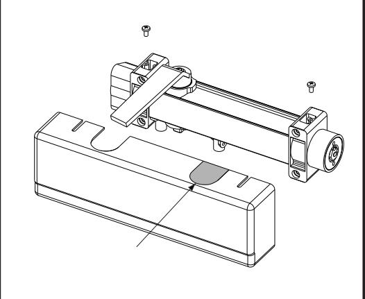
Insert is removable. Place in unused opening.
fire doors are involved.
SARGENT Manufacturing Company 100 Sargent Drive New Haven, CT 06511
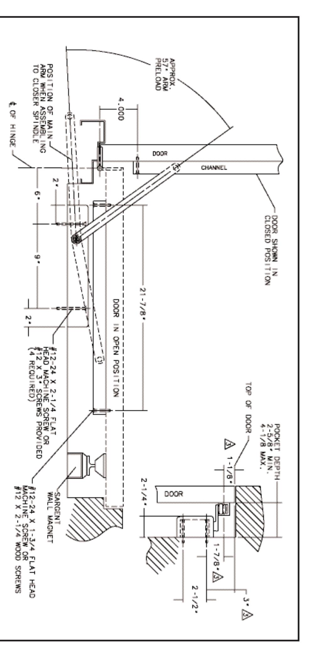
1. 12 GAUGE MIN. REINFORCEMENT REQUIRED FOR METAL DOORS AND FRAMES/WALLS
2. RIGHT HAND DOOR SHOWN, LEFT HAND OPPOSITE
DATA SHEET: 351-OP WALL P DOOR CLOSER
POCKET INSTALLATION
EFFECTIVE DATE 10 PMS TEMPLET NO.
m
A7414
ASSA ABLOY, the global leader in door opening solutions
SARGENT ASSA ABLOY
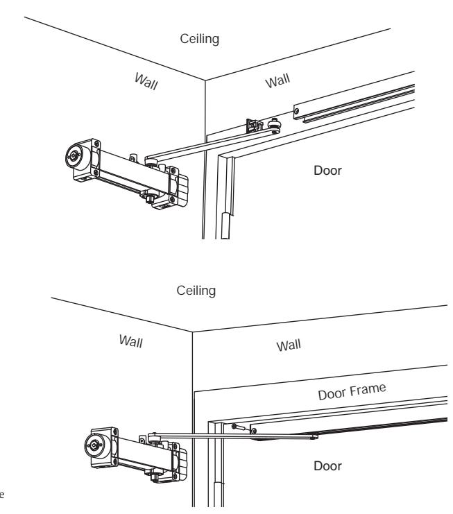
351 DOOR CLOSER WITH TRACK TYPE ARM (OTP) INSTALLATION INSTRUCTIONS
Strength Adjustable From Size 1 Thru 6
CAUTION: FAILURE TO INSTALL OR ADJUST PROPERLY MAY RESULT IN INJURY OR DAMAGE Auxiliary door stop required
FOR ASSISTANCE, CALL SARGENT AT 1-800-727-5477 or www.sargentlock.com
Step 1: Use template on page 3 to drill and tap door and wall for 12-24 machine screws or predrill when using self tapping screws provided. See page 2 for when using mortise nuts
Step 3: Secure door closer to wall using screws provided with spring power facing away from hinge.
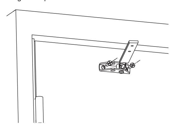
Step 4: Insert roller into track. Insert end caps and secure track to door with screws provided.
Adjusting Closing Speeds
Closing and latching speeds:
Turn valves clockwise to slow down or counterclockwise to speed up door movement.
Backcheck:
Turn valve clockwise to increase or counterclockwise to decrease.
CAUTION: SET VALVE FOR SLIGHT CUSHIONING EFFECT. CLOSER CAN BE DAMAGED IF THE CHECKING ACTION IS TOO ABRUPT. NEVER USE THE BACKCHECK AS A DOOR STOP. ALWAYS USE A DOOR STOP TO STOP THE DOOR.
Delayed action feature (optional feature):
When provided, turn valve clockwise to slow down or counterclockwise to speed up door movement.
Adjusting Closing Power
- Increase closing force to achieve proper door latching.
- Decrease closing force if the door is difficult to open.
INSTALLATION GUIDE
| Number of Turns of Spring Power Adjusting Nut | ||
|---|---|---|
|
Door Width
(Inches) |
Exterior Doors | Interior Doors |
| 24-30 | TURN nut 1-3 | TURN nut 1-3 |
| 30-36 | FACTORY SET | FACTORY SET |
| 36-42 | TURN nut 1-4 | TURN nut 1-3 |
| 42-48 | TURN nut 7-9 | TURN nut 4-6 |
Adjusting door to close due to high draft conditions may exceed ADA standards. Consult local ordinances when fire doors are involved.
Copyright © 2005, 2008, Sargent Manufacturing Company, an ASSA ABLOY Group company. All rights reserved. Reproduction in whole or in part without the express written permission of Sargent Manufacturing Company is prohibited.

| A 75 24 A | SARGENT WALL MAGNET |
|---|---|
| TEMPLATE NO. | WITH BUTT HINGES AND |
| R 10 AUG 05 | 351-OTP SERIES DOOR CLOSER |
| State Sand Sand | DATA SHEET: |
| n. (7 06811 | 100 Sargent Drive New Have |
| og Company | SARGENT Manufacturi |