Instructions for Installation and Wiring Remote Options to SARGENT AL-Prefix 80 Series Alarmed Exit Devices using the 546 Wiring Harness to ElectroLynx Connector System
Open the original PDF document
View PDFInstructions for Installation and Wiring Remote Options to SARGENT AL-Prefix 80 Series Alarmed Exit Devices using the 546 Wiring Harness to ElectroLynx® Connector System
Hardwiring Made Easy™

SARGENT
ASSA ABLOY
ASSA ABLOY, the global leader in door opening solutions
FOR ASSISTANCE CONTACT SARGENT AT 800-810-WIRE (9473) or www.sargentlock.com
A. General
These instructions cover installing and wiring remote options to the AL- 80 Series Alarmed Exit Device using the 546 wiring harness. Refer to instruction A7224B for additional instructions. Remote options include Remote Power, Remote Monitor, Request to Exit (REX), Door Status and Remote Reset. In addition, there are field selectable options: REX/Passage Time Delay, Automatic Alarm Reset and Remote Monitor Relay Enable/Disable
B. Important
- 1. Caution: Disconnect all input power before beginning installation to prevent electrical shock and equipment damage
- 2. Installer must be a trained, experienced service person
- 3. All wiring must comply with applicable local electrical codes, ordinances and regulations
C. Connector System Notes:
The system is designed to be installation friendly with pluggable connectors from the electric hinge through the door to the rail. The only wiring required is to the loose wires on the pigtail harness assembly on the frame side of the electric hinge
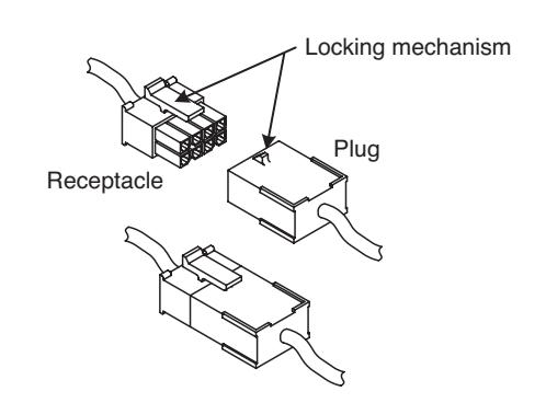
IMPORTANT.
The plug and receptacle connectors are designed to mate and lock together as shown in the figure. Plug the connectors into each other with the locking mechanism aligned as indicated

D. Installation Notes
- 1. With new applications, a raceway harness with 8 & 4-pin connectors will be pre-installed inside the door by ASSA ABLOY door manufacturers when specified during the ordering process. Raceway harness kits are also available for retrofit applications. For retrofit applications, refer to retrofit instructions
- 2. If door does not have a raceway harness with connectors, either consult factory for raceway retrofit kit or cut the connectors off product and hard wire as required
- 3. Wiring to pigtail harness is per facility wiring requirement. The rail, raceway, electric hinge and pigtail connector terminations and wire colors all match
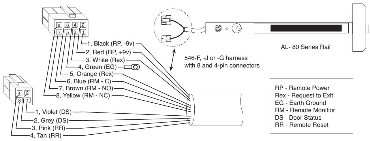
E. Remote Options - Input/Out Descriptions
Note: Refer to instruction A7224B REX/Passage and Automatic Alarm Reset Tables

| Pigtail | Circuit Board | Remote | |
|---|---|---|---|
| Connector | Connector | Option | Description |
|
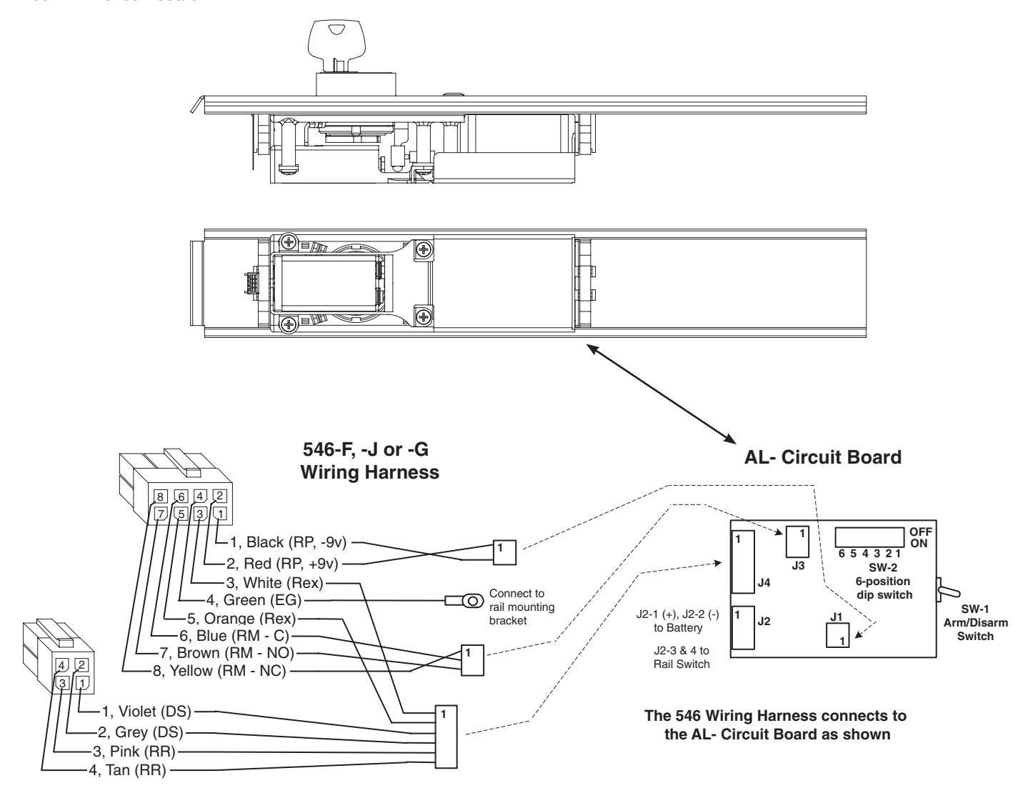
Black (-9v), 8-1
Red (+9v), 8-2 |
J1 - 2
J1 - 1 |
Remote Power
(Input) |
Allows unit to be connected to 9vdc power supply Model 3267
Refer to 3267 instructions A7477 |
|
White, 8-3
Orange, 8-5 |
J4 - 1
J4 - 2 |
REX
(Request to exit) (Input) |
Wired to normally open external switch or relay contact.
Momentary switch closure shunts rail, allows egress for selectable time of 7, 10, 15 or 20 seconds (see Passage Table), then rail rearms. Maintained switch closure shunts rail, allows egress until switch opens, then rail rearms after selectable passage delay of 7, 10, 15 or 20 seconds or portion of selected passage delay Note: LED flashes yellow during switch closure |
| Green, 8-4 | Earth Ground | Use to connect rail to 3267 power supply earth ground terminal | |
|
Blue (C), 8-6
Brown (NO), 8-7 Yellow (NC), 8-8 |
J3 - 2
J3 - 3 J3 - 1 |
Remote Monitor
(Output Relay) |
With unit armed, depressing push bar shall sound the alarm
and the output relay will change state until the unit is disarmed with a cylinder key, remote reset, or automatically reset after selectable time delay of 2, 5 or 10 minutes (see Automatic Alarm Reset Table). Note: Dip Switch SW-2 position 6 must be ON (Refer to SW-2 Table). SW-2 position 6 OFF disables output relay |
|
Violet, 4-1
Grey, 4-2 |
J4 - 3
J4 - 4 |
Tamper/Door Status
(Input) |
With door closed, wire to door status switch open contacts. With rail armed,
the alarm will sound when door is opened (switch is electrically closed). Alarm will sound until reset with cylinder key or automatic alarm reset time |
|
Pink, 4-3
Tan, 4-4 |
J4 - 5
J4 - 6 |
Remote Reset/Arm
(Input) |
Wired to normally open external switch or relay contact. When rail is
violated (alarm on), the rail alarm is reset and rail is rearmed as follows: Momentary switch closure resets alarm, then rail is rearmed after selected passage time of 7, 10, 15 or 20 sec (see Passage Table). Maintained switch closure resets alarm/keeps rail disarmed. When switch is reopened, the rail rearms after selected passage time Note: LED remains OFF. Recommended for remotely disarming rail long term |
|
Red (+), J2 - 1
Black(-), J2 - 2 |
Battery
(Input) |
Connects 9vdc battery to circuit board | |
|
Gray, J2 - 3
Black,J2 - 4 |
To Internal
Rail Switch (Input) |
Wired normally open and mechanically held (maintained) closed.
Alarm activates when switch is electrically opened (when push bar is depressed) |
F. Dip Switch (SW-2, 6-position)
Factory settings shown. Refer to instruction A7724B for field selectable settings.
- 1. DS-1 = OFF, DS-2 = OFF REX / Passage Delay (set to 7 seconds)
- 2. DS-3 = OFF, DS-4 = OFF Automatic Alarm Reset (set to 2 minutes)
- 3. DS-5 = ON Selects LED color (Armed = Green, Violation = Red, Passage = Yellow)
- 4. DS-6 = ON Monitor Relay is enabled (will activate when rail is violated)

ASSA ABLOY
G. AL- Circuit Board and 546 Harness
Printed Circuit Board
Note: SW-1, Arm/Disarm Switch shown in ON (armed) position
AL-Insert with circuit board
H. AL- 80 Series Exit Device Installation
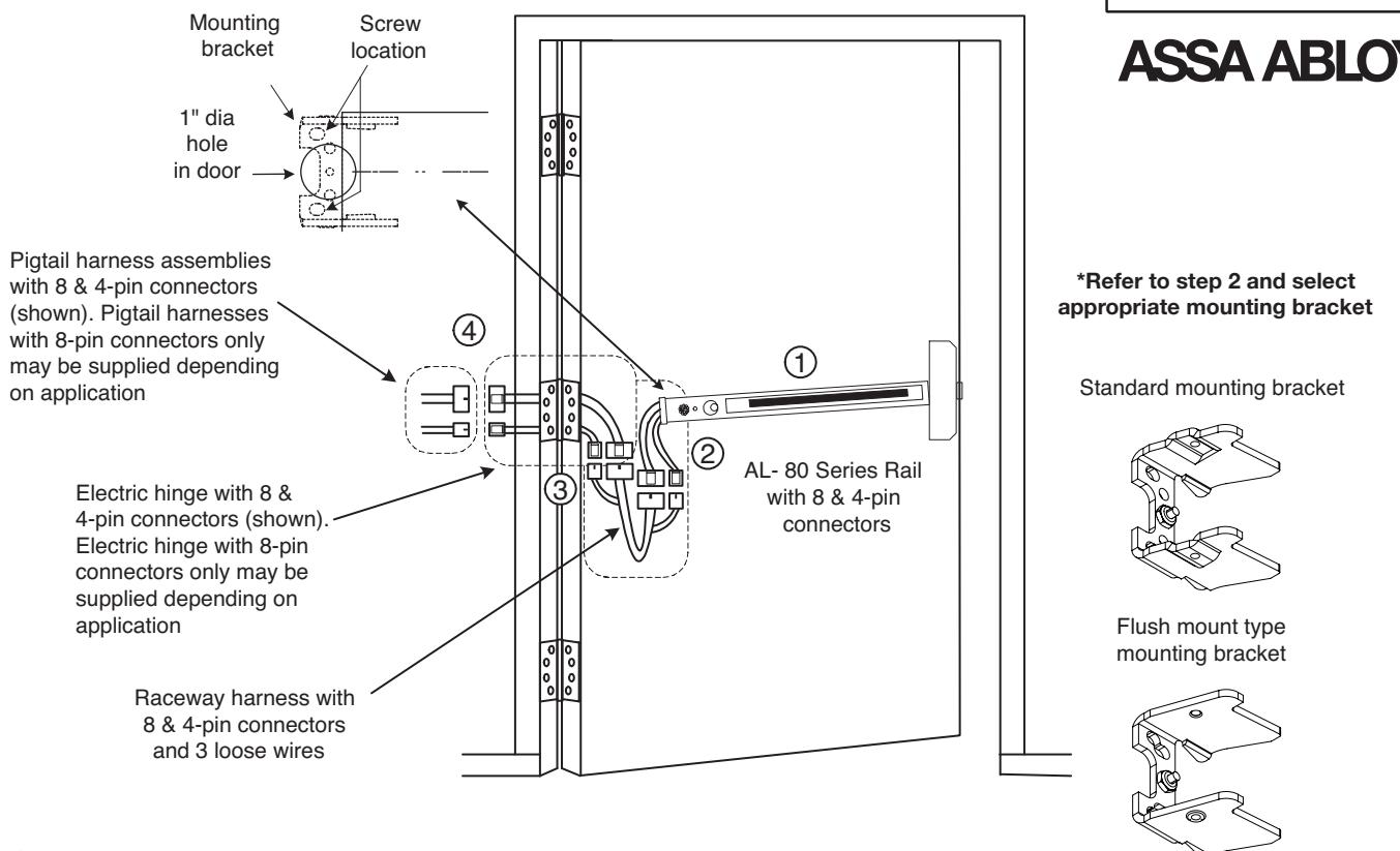
- Finish mounting exit device per instruction sheet provided 1
- Supplied with the 546 kit are two types of rail mounting brackets (standard & flush mount) Select appropriate mounting bracket according to rail end cap type being installed End caps stamped SARGENT are standard and end caps stamped SARGENT 80 are flush mount Remove nut on mounting bracket, place lug from green wire on 546 harness on to center screw on mounting bracket, then re-install nut and tighten 2
Plug rail connector(s) into raceway connector(s). Then feed through 1" hole in door Install rail mounting bracket with two screws supplied. Install rail end cap
To ensure trouble free operation, check that the push rail can be fully depressed. On vertical rod exit devices, adjust rods and check that the latch bolts do not go into hold back position until the push rail is fully depressed
- Plug raceway connector(s) into electric hinge connector(s) then feed through door prep Note: Electric hinge will have two 8-pin connectors or two 8-pin and two 4-pin connectors Mount electric hinge to door side only 3
- Go to (A) if wiring now. Go to (B) if wiring is to be done later 4
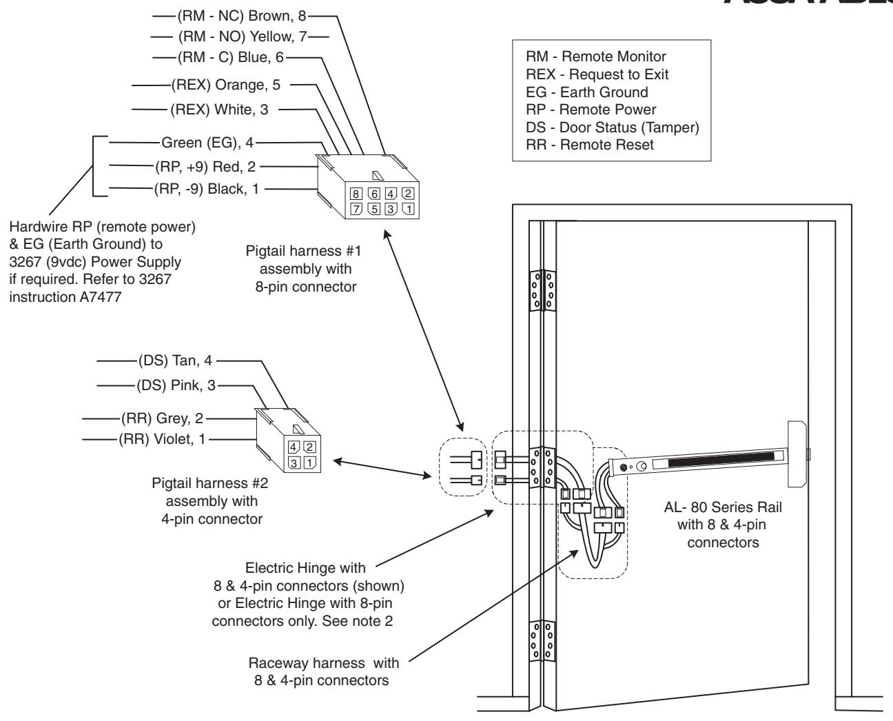
- A. Determine which Remote Options need to be wired per facility requirement Refer to Remote Options Table and Wiring
Wire to loose wires on pigtail harness(es) as required using connectors allowed by local code. Plug pigtail harness connector(s) into electric hinge connector(s) Feed harnesses through frame prep and mount electric hinge Ensure wiring is correct then apply power and test exit device Refer to page 6 of this instruction and instruction A7224B for rail operating instructions
B. Plug pigtail harness connector(s) into electric hinge connector(s) Feed harness(es) through frame prep and mount electric hinge
I. Wiring to AL- 80 Series Remote Options

Notes:
- 1. Pigtail assemblies, electric hinge, raceway harness and rail connector terminations and wire colors all match
- 2. An electric hinge with 8-pin connectors only or 8 & 4-pin connectors is required depending on which Remote Options are required
A. Remote Options requiring an Electric Hinge with 8-pin connectors only :
RM - Remote Monitior REX - Request to Exit RP - Remote Power
B. Remote Options requiring an Electric Hinge with 8 & 4-pin connectors :
RR - Remote Reset DS - Door Status (Tamper) with or without options listed in A
3. Wire to pigtail harness assemblies per facility requirement
J. Operational Notes (Refer to this instruction and instruction A7224B)
Once power is connected, turning the key clockwise activates the alarm. A field settable time delay of 7, 10, 15 or 20 seconds (refer to Instruction Manual A7224) is initiated prior to the rail going into armed state. This delay allows the individual who is setting the alarm, time to exit without setting off the alarm. The LED will flash yellow during this time.
Once the unit is armed, the horn will chirp one time and the LED will flash green and repeat every 30 seconds to indicate the unit is armed. Once armed, depressing the push bar will sound the alarm. The rail alarm will sound until it is disarmed by one of three methods.
- (1) Using a rail cylinder key,
- (2) Remote reset/arm switch signal, or
- (3) It will automatically reset after an optional field settable time delay of 2, 5, 10 minutes.
The LED will flash Red every 30 seconds to indicate the rail has been violated and will continue to flash Red until the unit has been reset manually. If battery powered and low battery voltage is detected, the horn chirps quickly and repeats every 10 seconds until the battery is replaced.