Instructions for 7800, 8200 Mortise Locks Functions
Open the original PDF document
View PDF7800/8200 Series Mortise Locks Multi-function Lockbody Options 04, 05, 06, 13, 31, 36, 37, 38
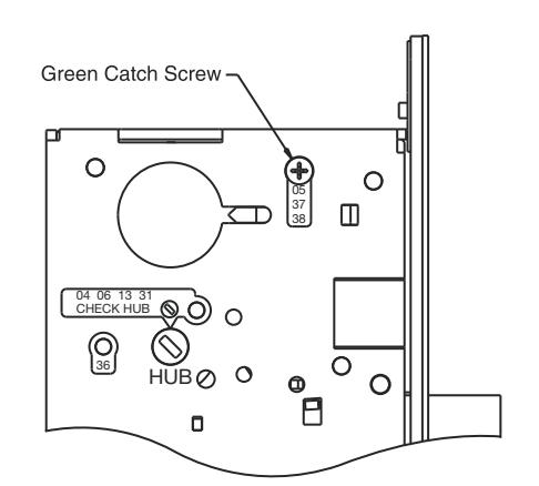
How to Change Function of Lock:
One green catch screw must be located in following three (3) locations as designated on lock case to create desired function:
- 1. 05, 37 and 38 functions
- 2. 04. 06. 13 and 31 functions
- 3. 36 functions
When moving green catch screw to 04, 06, 13 and 31 functions, hub position must be at 45° as shown on lockcase.
*See How to Change Hand of Lock, page 6

| Items needed to create following functions: | ||||||||
|---|---|---|---|---|---|---|---|---|
| Function |
Outside
Lever |
Inside
Lever |
Trim One
Side Kit |
Outside
Cylinder |
Inside
Cylinder |
Thumb
Turn |
||
| 04 | Х | Х | _ | Х | _ | _ | ||
| 05 | Х | Х | _ | Х | _ | X*** | ||
| 06 | _ | Х | х | Х | _ | _ | ||
| 13 | _ | Х | х | _ | _ | _ | ||
| 31 | _ | Х | Х | Х | _ | _ | ||
| 36 | _ | Х | Х | Х | _ | _ | ||
| 37 | Х | Х | _ | Х | _ | _ | ||
| 38 | Х | Х | _ | Х | Х | _ | ||
- *** 130 KB thumb turn is used with rose trim only, escutcheon trims requiring thumb turns, must be preassembled at factory.
- #41 Cylinder is standard for both single and double cylinder functions for 1-3/4" thick door.
Note
ASSA ABLOY, the global leader
in door opening solutions
Trim-one-side functions always require an inside trim assembly which can be used inside or outside of door (to order Trim-one-side kit (for all trim except PT or FE) order part #82-4611.
SARGENT 8200 Series Mortise Locks Function List
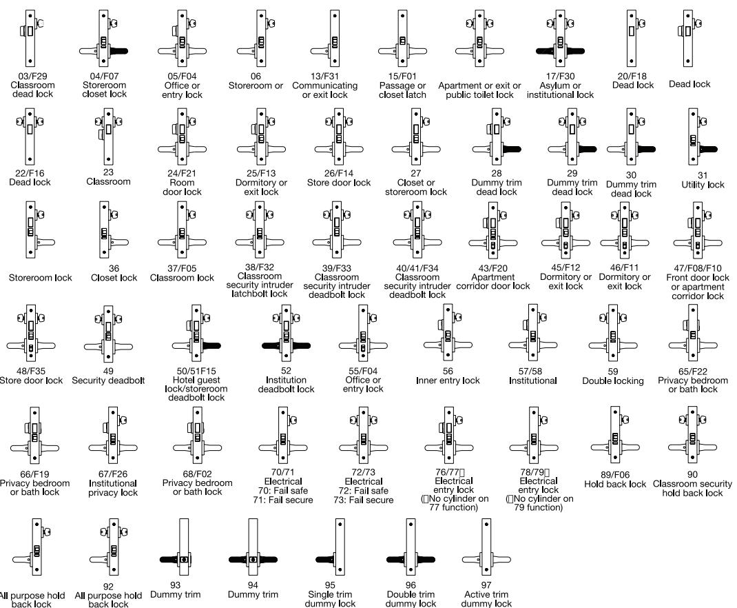
Shaded levers are rigid at all times.
05 Function has thumb turn inside of door and 55 Function has toggle on lock front.
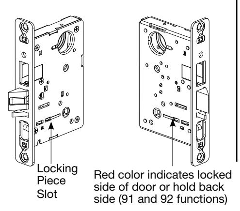
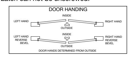
How To Change Hand of Lock
of latch:
- 1. Red surface of locking piece must face locked side of door.
- Position lockbody with red surface of locking piece visible.
- Insert blade type screwdriver into locking piece slot to rotate locking piece.
- Push locking piece toward back of lockbody and rotate 180° until red surface shows on opposite side.
Note
For 04, 06, 13, 17 and 31 functions:
- a. Remove green catch screw.
- b. Rotate hub to 45° position.
- c. Rotate locking piece for required hand.
- d. Face red surface to locked side of door. e. Rotate hub to original 45° position (as
- shown on lockcase). f. Reinstall green catch screw.
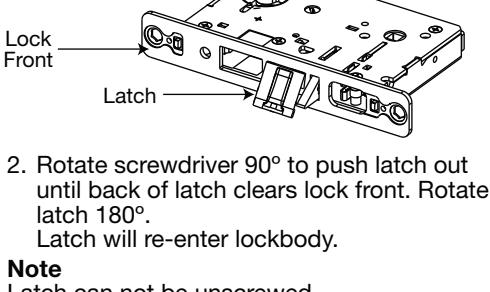
Beveled surface of latch must face strike.
Deadlatch is self adjusting. To change hand
Insert screwdriver
blade into spade
6
shaped slot.
Latch can not be unscrewed
Installation Instructions 7800 Series Knobs/8200 Series Lever Mortise Locks
SARGENT ASSA ABLOY
WARNING
Standard 7800/8200 Series Mortise Locks Sectional Trim Description and Part Number
To view QR Code video clips within this document, download a free mobile app and scan QR Code with your mobile device.
· Phillips and flat tip screwdriver
Installation for levers and knobs is identical

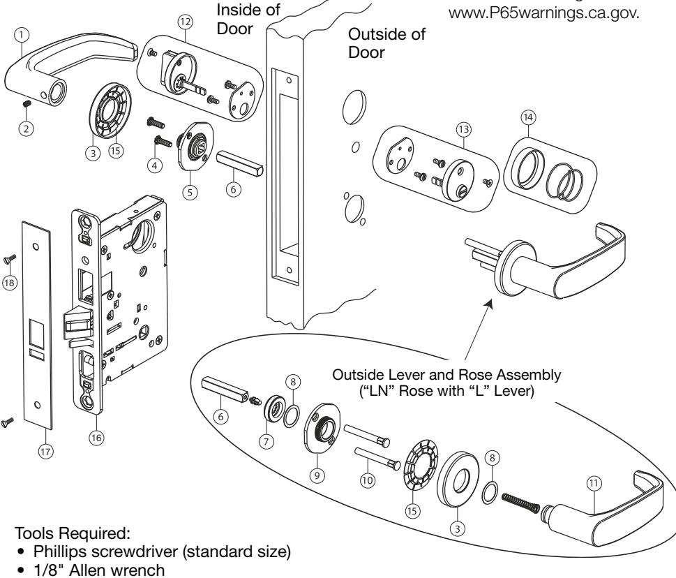
| Part No. | Description | Req. | |
| 1 | Varies | Inside lever handle – consult factory | 1 |
| 2 | Handle set screw 1/4-28 UNF | 1 | |
| 3 | 81–0093 | Rose – "LN" design | 2 |
| 4 | 01–1495 | Machine screw #8-32 x 5/8" | 2 |
| 5 | 82–3088 | Inside adapter and plate assembly | 1 |
| 6 | 82-0368 | Spindle | 2 |
| 7 | 82-0184 | Cap nut | 1 |
| 8 | 01–0079 | Washer | 2 |
| 9 | 82–3082 | Adapter and plate assembly (LN design) | 1 |
| 10 | 81–0723 | Mounting post | 2 |
| 11 | Outside lever handle – consult factory | 1 | |
| 12 | 77–3279 | Turn lever assembly – 130KB design | 1 |
| 13 | 77–2595 | Emergency button assembly – 184KB | 1 |
| 14 | 77–0509 | KB cylinder rosette (for 8200) | 1 |
| 15 | 82–0612 | Non-loosening wave spring | 2 |
| 16 | Varies | Lockbody | 1 |
| 17 | Varies | Outside front | 1 |
| 18 | 01–102 | Machine Screw #8-32 x 1/4" | 2 |
Copyright © 2016, 2019, SARGENT Manufacturing Company. All rights reserved. Reproduction in whole or in part without the express written permission of SARGENT Manufacturing Company is prohibited.
ASSA ABLOY
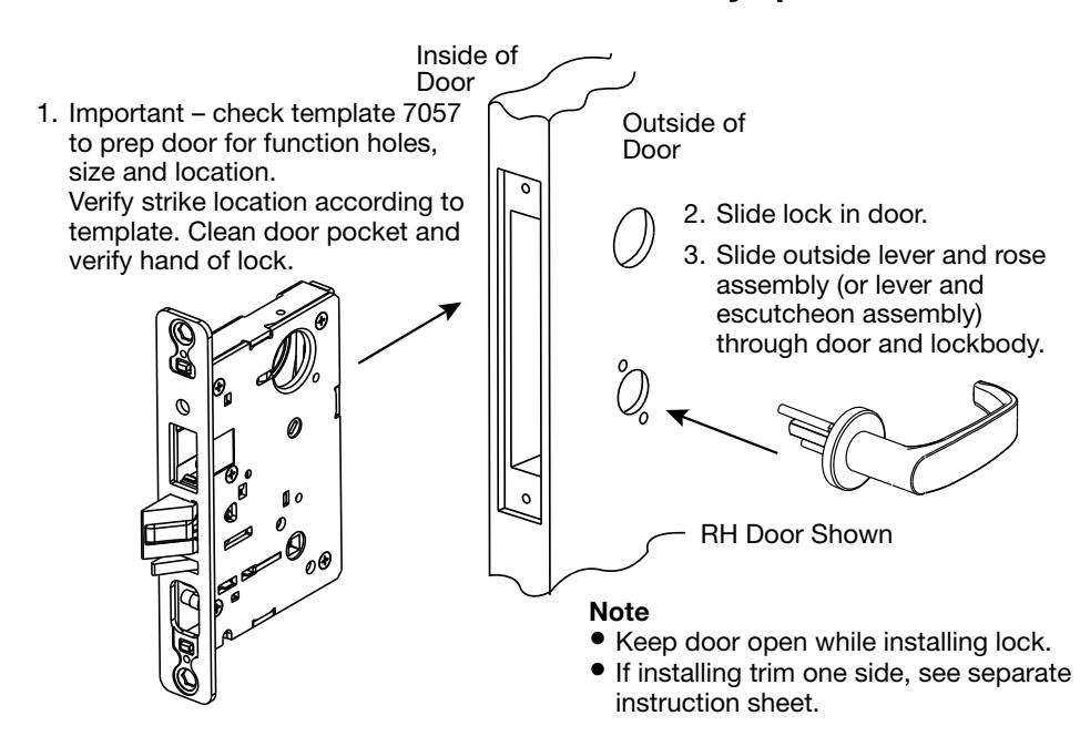
Installation Instructions for 7800/8200 Series Mortise Locks (Except PT Trim and FE Trim) See trim section to identify specific lock.
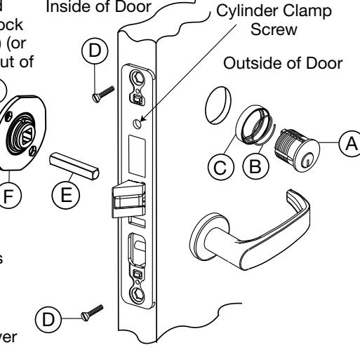
4. Slide cylinder (A) through spring (B) and collar (C) (or escutcheon). Thread into lock until cylinder face is flush with collar (C) (or escutcheon) edge. Key slightly pulled out of cylinder will help thread cylinder.
2 A7772:H
SARGENT logo must be horizontal and on top portion of cylinder.
- Tighten cylinder clamp screw by hand with #2 Phillips screwdriver.
- Secure lock in door with two (2) wood screws #12 x 1-1/4" or machine screws #12-24 x 1/2" (D).
- 7. Slide spindle (E) into lockbody hub.
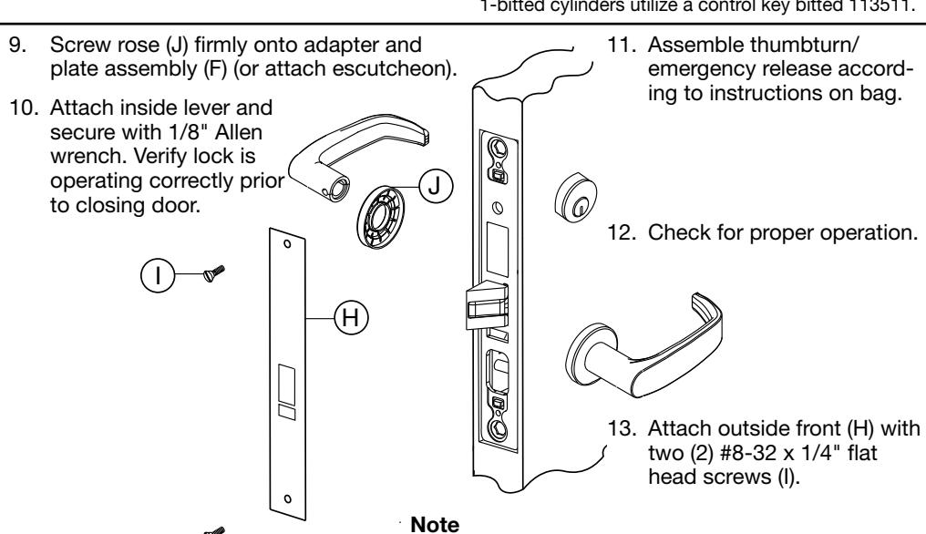
- Slide adapter and plate assembly (F) over spindle and secure with two (2) #8-32 screws (G).
Inside of Door
R/C and I/C cylinder cores require control key (stamped "C") to install. Must request separately. 1-bitted cylinders utilize a control key bitted 113511.
Check for proper lock operation by function number (ex.: 8205=05 function). See 7800/8200 Series
catalog (www.sargentlock.com).
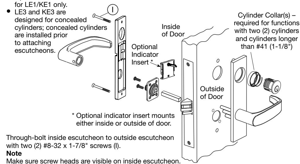
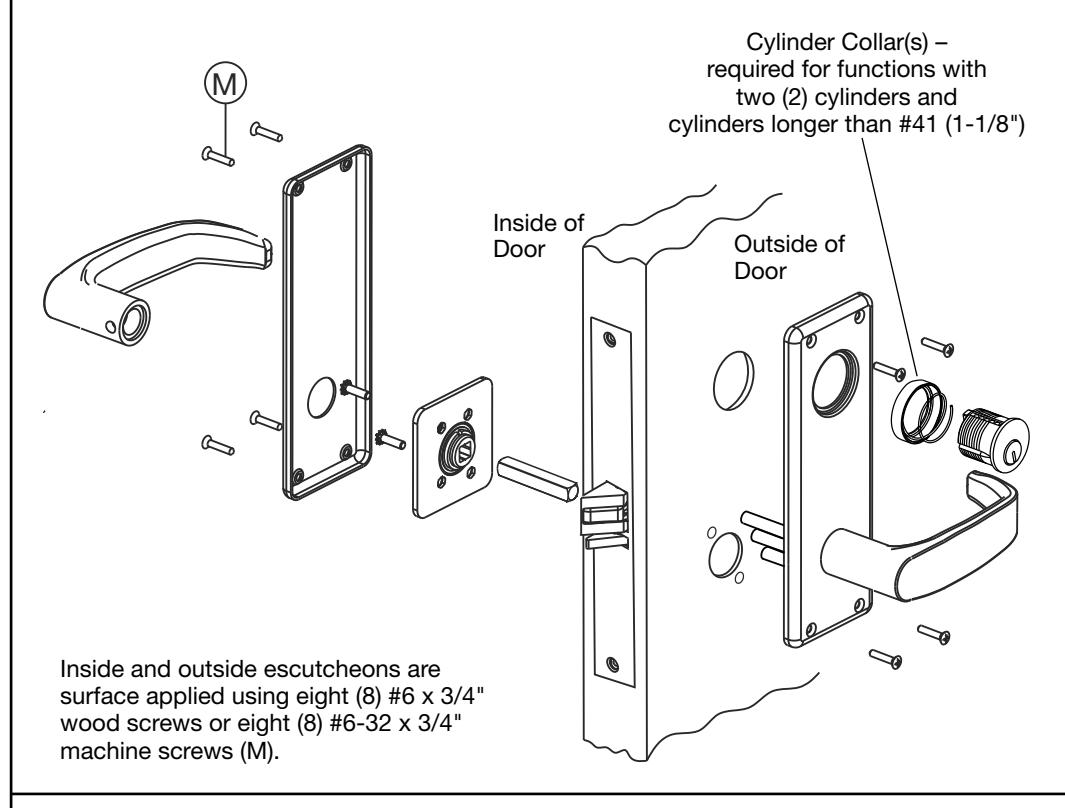
TE, CE, LE1, KE1, LE3, KE3, LW1 and KW1 Escutcheon Installation
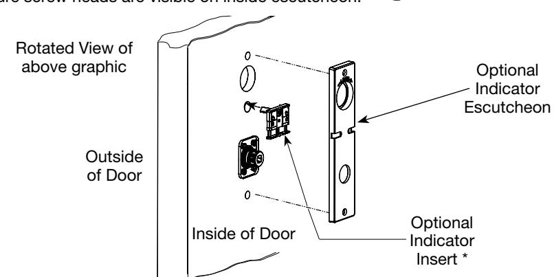
Optional Indicator Insert Installation:
- 1. Mount outside escutcheon and inside mounting plate per standard instructions.
- 2. If applicable, mount indicator insert on inside or outside of door by inserting spindle into mortise hub and continue with standard installation of inside escutcheon.
Optional indicator insert available
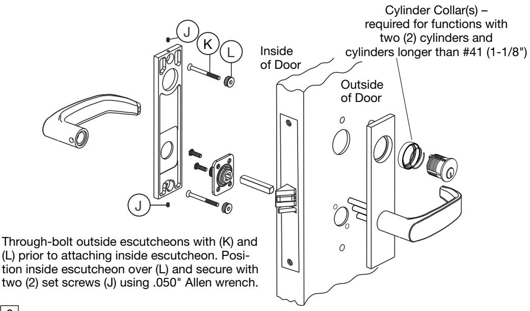
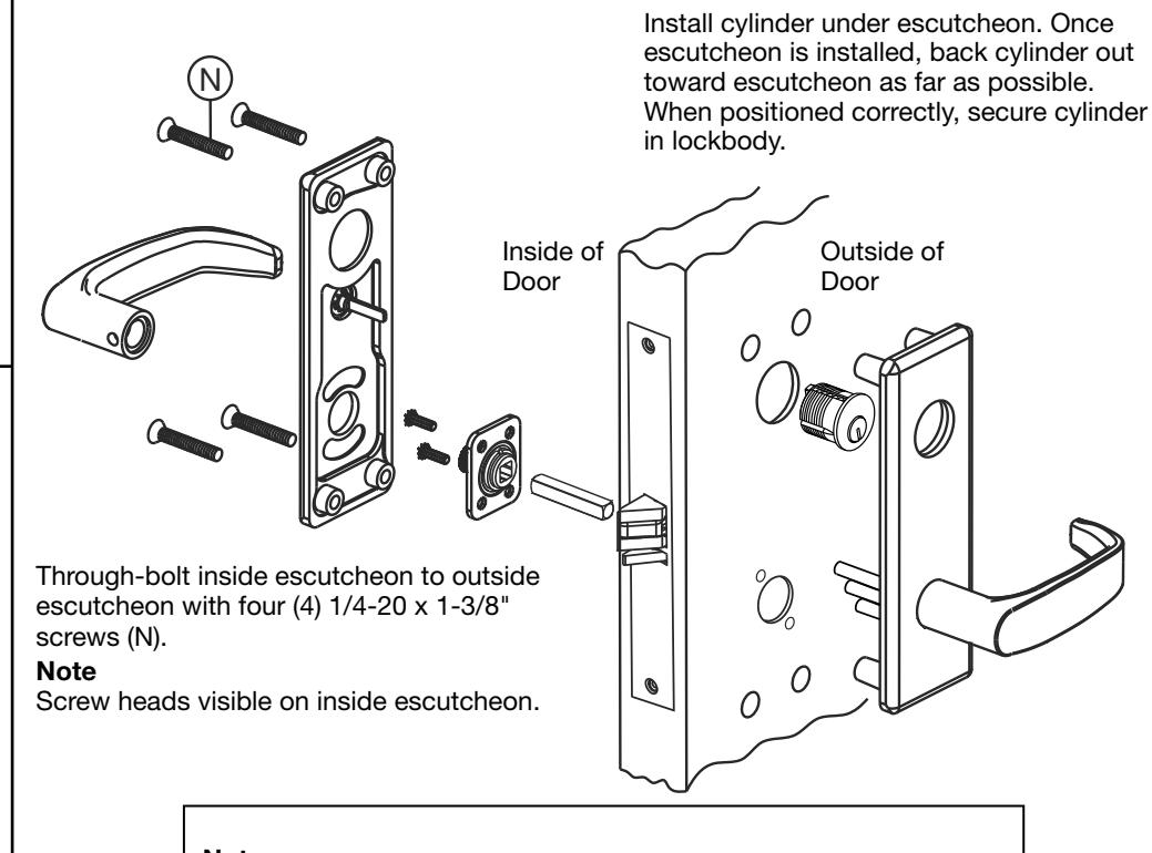
LE2, LE4, KE2 and KE4 Escutcheon Installation
LE4 and KE4 are designed for concealed cylinders; concealed cylinders are installed prior to attaching escutcheons.
WT Escutcheon Installation
LS and KS Security Escutcheon
4
To install double cylinder functions using supplied cylinder retaining cap:
- 1. Install:
- both cylinders,
- cylinder retaining cap (over each cylinder) and
- escutcheons.
- 2. Back cylinders out and secure in place.
Copyright © 2016, 2019, SARGENT Manufacturing Company. All rights