Instruction Sheet for #607 Locking Slide Replacement Kit
Open the original PDF document
View PDFInstallation Instructions

607 Locking Slide
Replacement Kit
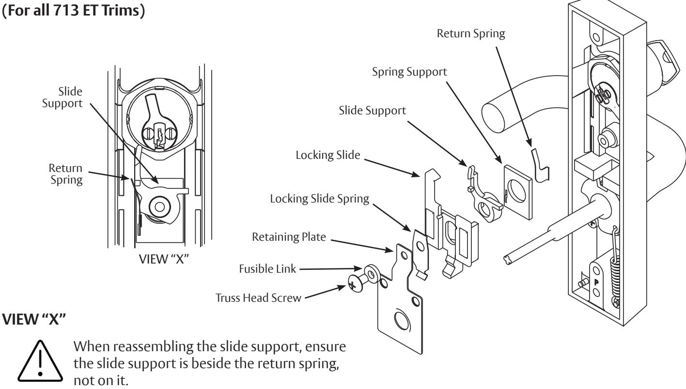
607-1 Locking Slide Replacement Kit
On Lockable ET Controls:
- 1. Remove the truss head screw, fusible link, locking slide spring, retaining plate and locking slide.
- 2. Place the new locking slide over the slide support and return spring making sure that the slide support is beside the return spring. Note: See View "X" for proper installation of slide support, spring support, and return spring.
- 3. Align the locking slide spring, retaining plate, fusible link, and truss head screw.
- 4. Tighten securely.

This product can expose you to lead which is known to the state of California to cause cancer and birth defects or other reproductive harm. For more information go to www.P65warnings.ca.gov.
1-800-727-5477 • www.sargentlock.com A7411C 8/22

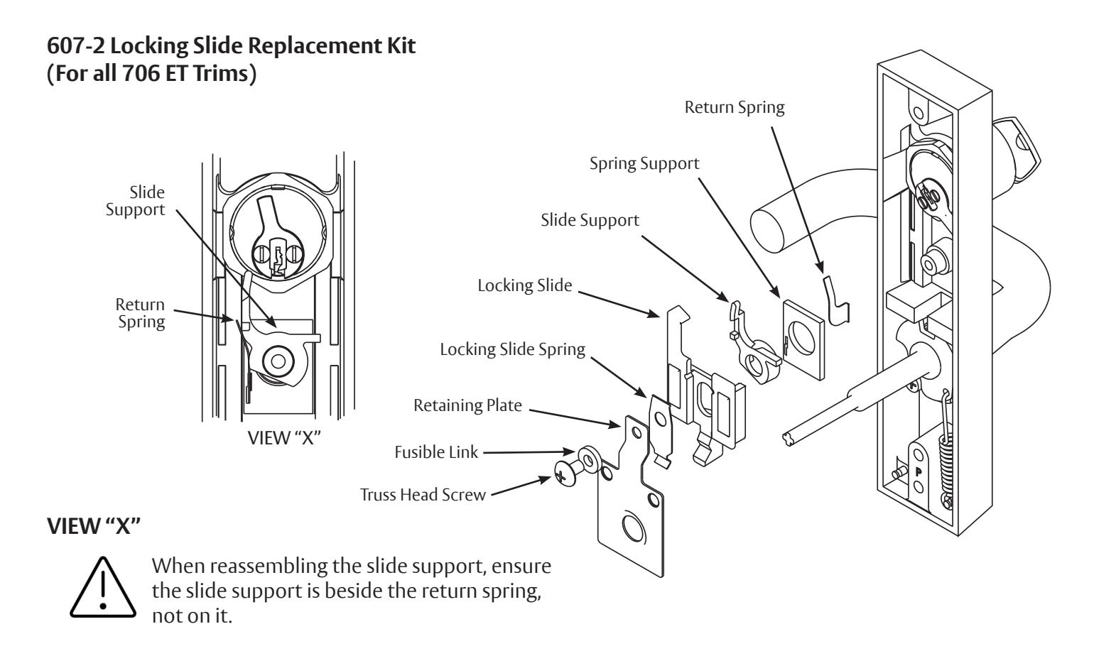
On Lockable ET Controls:
- 1. Remove the truss head screw, fusible link, locking slide spring, retaining plate and locking slide.
-
2. Place the new locking slide over the slide support and return spring making sure that the slide support is beside the return spring.
- Note: See View "X" for proper installation of slide support, spring support, and return spring.
- 3. Align the locking slide spring, retaining plate, fusible link, and truss head screw.
- 4. Tighten securely.
prohibited.

607-3 LOCKING SLIDE REPLACEMENT KIT (For all 743 ET Trims)
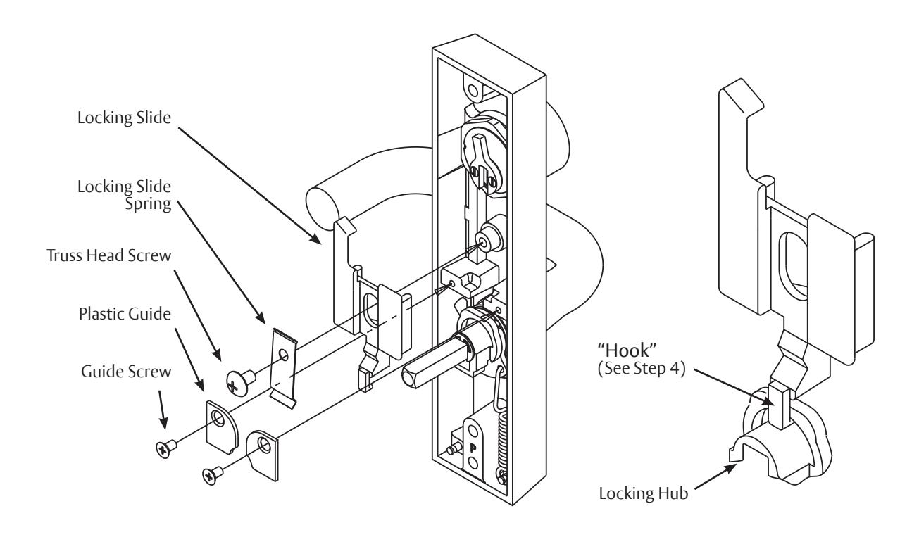
On Free Wheeling ET Controls:
- 1. Remove and save the two plastic guides and the guide screws.
- 2. Remove and discard the truss head screw and slide spring.
- 3. Remove and discard the locking slide, noting how it was installed.
- 4. Place the new locking slide into the ET case. Be sure to put the "hook" of the slide into the slot of the locking hub.
- 5. Place the new spring on the slide as shown and align the hole in the spring with the post.
- 6. Install the truss head screw and tighten securely.
- 7. Reinstall the guides and guide screws as shown.
The ASSA ABLOY Group is the global leader in access solutions. Every day we help people feel safe, secure and experience a more open world.
607-4 & 607-5 LOCKING SLIDE REPLACEMENT KIT (For all 746 ET Trims)
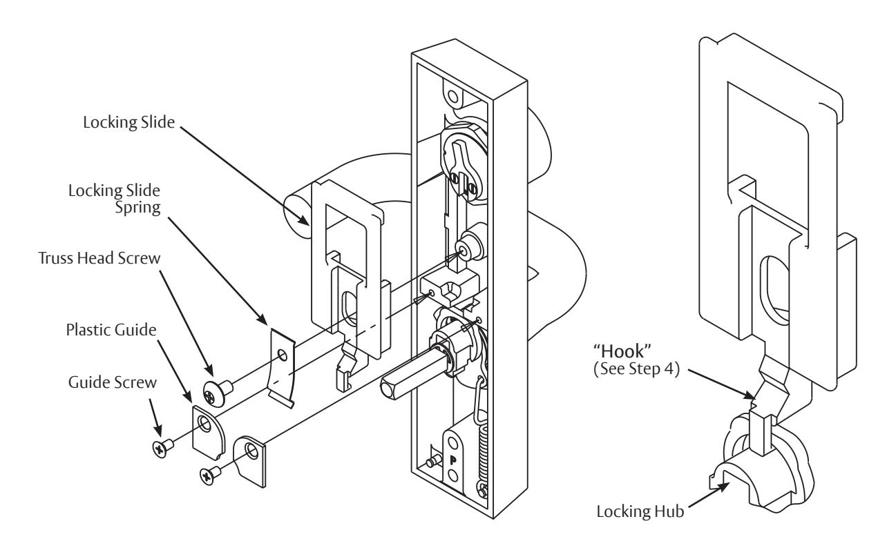
On Free Wheeling ET Controls:
- 1. Remove and save the two plastic guides and the guide screws.
- 2. Remove and discard the truss head screw and slide spring.
- 3. Remove and discard the locking slide, noting how it was installed.
-
4. Place the new locking slide into the ET case. Be sure to put the "hook" of the slide into the slot of the locking hub.
- Note: The cylinder cam must point up for proper operation.
- 5. Place the new spring on the slide as shown and align the hole in the spring with the post.
- 6. Install the truss head screw and tighten securely.
- 7. Reinstall the guides and guide screws as shown.
SARGENT Manufacturing Company 100 Sargent Drive New Haven, CT 06511 USA 800-727-5477 www.sargentlock.com
1-800-727-5477 • www.sargentlock.com A7411C 8/22