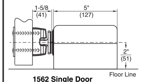
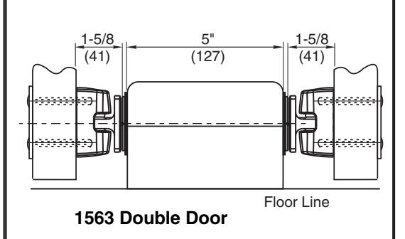
Instruction Sheet for 1562 Single Door-1563 Double Door Release
Open the original PDF document
View PDF

ASSA ABLOY
All electric box anchoring shall withstand 50 lbs of pull or push force.
Verify line voltage.
See Page 2 to complete this installation.
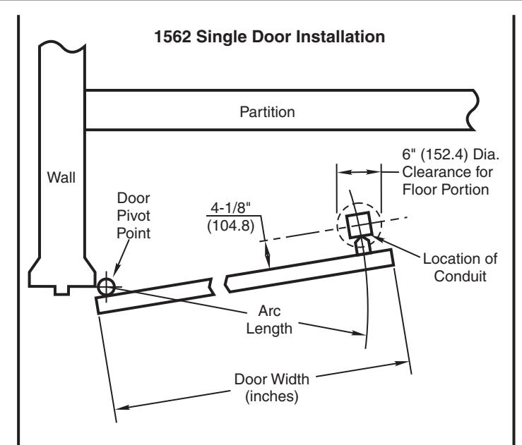
- 1. Determine pivot point of door.
- 2. Determine door width (inches).
- Determine maximum degree of door opening permitted by door closer, trim and partition.
To Locate Conduit:
1. Determine "arc length" (see drawing).
Arc Length = Width of Door (inches) minus 5-5/8" (143mm) Example: To determine "arc length" of 3'0" (914mm) door Width of Door (inches) 36" (914mm) Minus 5-5/8" (143mm) Arc Length = 30-3/8" (771.5mm)
- Determine maximum degree of desired door opening (closer, trim or partition permitting). Allow a 6" (152mm) diameter clearance around conduit and any partition for the floor mount 1562. (See drawing.)
- Conduit will be located on the arc and 4-1/8" (105mm) from the pull side of door when the door is at the maximum degree of door opening.
1563 Double Door Installation Door Pivot Point Arc _enath Wall 8-1/4" (209.6)Location of Min. Conduit Door Pivot Length Point Door Width (inches)
- 1. Determine pivot point of door.
- 2. Determine door width (inches).
- Determine maximum degree of door opening permitted by door closer (maximum degree of opening 130°).
To Locate Conduit:
1. Determine "arc length" (see drawing).
- Strike "arc lengths" from pivot points of doors. Conduit will be located where the two arcs intersect. (See drawing.)
- 3. 8-1/4" (210mm) minimum space required between pull sides of doors for full 90° opening. (Maximum degree of door opening 130°).
REV-2
INSTALLATION INSTRUCTIONS 1562/1563 DOOR RELEASE
Floor Mounted Application
For installation assistance, contact SARGENT at 800-727-5477 • www.sargentlock.com
SARGENT
ASSA ABLOY
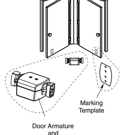
Door Armature
and
Electromagnet
See Page 1 for electric box location.
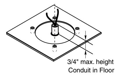
2 Place anchors in floor. Align anchor holes using magnet mounting bracket assembly for hole placement.
3 Place gasket on floor aligning gasket holes with anchors.
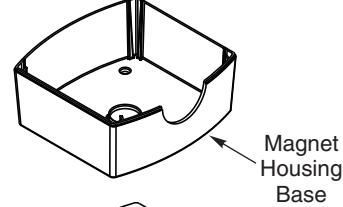
4 Place magnet housing base on gasket.
5 Connect power. 24VAC/VDC
• For coils that are tri-volt put ground wire in "Com". Put power wire in correct voltage slot on strip.
For coils with two wires attach one wire to ground. Attach one wire to power. Coil is non-polarized so it doesn't matter which wire is attached to which.
Ground floor portion assembly to earth ground per state and local regulations.
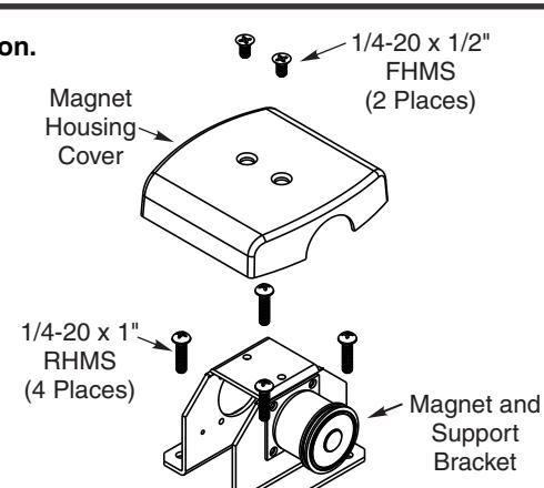
6 Place magnet mounting bracket assembly in base and screw into anchors. Make sure seal is tight around cover and base.
7 Screw magnet housing cover to mounting bracket assembly.
8 Loosen contact plate adjustment screw.
9 Remove paper.
10 Turn power on.
120VAC 12VDC

CAUTION: Nicks and scratches on the metal ring of the coil will lessen or diminish the holding force of the magnet. Do not remove protective cap until last steps of installation.
11 Place armature flat on coil.
Make sure round solenoid is completely covered by contact plate **If coil cannot be energized yet, hand hold contact plate on magnet and complete next steps.
2 Open door against armature on floor.
13 Tighten contact plate on armature.
14 Pull door away leaving mounting template sticking to face of door.
|5 Select Thru Bolt or Surface mounting option.
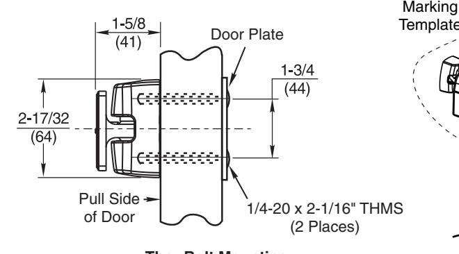
Thru Bolt Mounting Recommended for Hollow Metal, Hollow
Recommended for Hollow Metal, Hollow Core or Composite Type Wood Doors
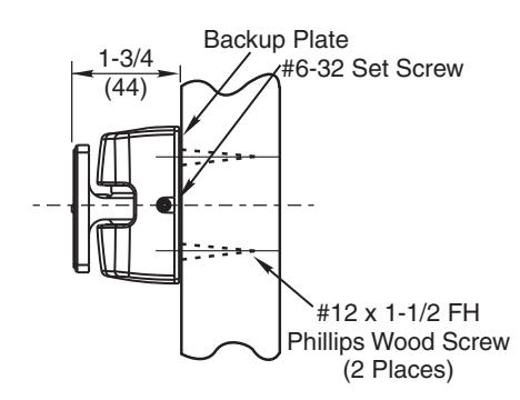
Surface Applied Concealed Mounting Recommended for Solid Wood Doors Only
Electromagnet
16 Affix to door.
REV-2
Screw
Paper