Instruction Sheet for 1560 Door Release
Open the original PDF document
View PDFINSTALLATION INSTRUCTIONS 1560 DOOR RELEASE
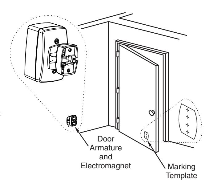
Surface Mounted Application
For installation assistance, contact SARGENT at 800-727-5477 • www.sargentlock.com

ASSA ABLOY
- 1. Use table to locate Surface Adapter Housing.
- 2. Determine door width (Dim "B"). Measure pivot centerline to wall (Dim. "A"). Find dimension "C" in table.
Example: Pivot centerline to wall ("A") = 10" (254mm)
Door Width ("B") = 36" (914mm)
Surface Adapter Housing Centerline ("C") = 33" (838mm)
3. If "A" or "B" falls between the numbers listed in table, allow for difference.
Example: Pivot centerline to wall ("A") = 17" (432mm)
Door Width ("B") = 36" (914mm)
Surface Adapter Housing Centerline ("C") = 31" (787mm)
- 4. If dimensions "A" and "B" intersect in shaded area of table DO NOT INSTALL Surface Adapter Housing. The degree of door opening will not permit proper alignment between armature and wall magnet.
- 5. Vertical location to be determined by others. Suggested height is 2' to 4' (610mm to 1219mm) from floor and/or not over 6' (1829mm).
- 6. Check degree of door opening in table and coordinate with door closers and other door hardware.
| Location of Surface Adapter Housing | |||||||||
|---|---|---|---|---|---|---|---|---|---|
| Α | → | Door Jamb | |||||||
| ζ { | |||||||||
|
|
cs |
B
Surface Adapter Housing |
|||||||
- "A" Door Jamb to Wall
- "B" Door Width
- "C" Pivot Centerline to Surface Adapter Housing
All Surface Adapter Housing anchoring shall withstand 50 lbs of pull or push force.
Verify line voltage.
See Page 2 to complete this installation.
| Sui | lace Ac | лартет п | lousing | Centen | ine ( C | ) = 31" ( | /0/11111 | 1) | ||||||||||||||
|---|---|---|---|---|---|---|---|---|---|---|---|---|---|---|---|---|---|---|---|---|---|---|
| [ | Door Wid | dth "B" | ||||||||||||||||||||
| Dim. | 28" ( | 711) | 30" ( | 762) | 32" | (813) | 34" ( | 864) | 36" ( | 914) | 38" ( | 965) | 40" ( | 1016) | 42" (1 | 1067) | 44" ( | 1118) | 46" ( | 1168) | 48" (1 | 219) |
| "A" | "C" | Deg. | "C" | Deg. | "C" | Deg. | "C" | Deg. | "C" | Deg. | "C" | Deg. | "C" | Deg. | "C" | Deg. | "C" | Deg. | "C" | Deg. | "C" | Deg. |
| 2" (51) |
26"
(660) |
87° |
28-1/8
(714) |
87° |
30-1/8
(765) |
87° |
32-1/8
(816) |
88° |
34"
(864) |
89° |
36"
(914) |
89° |
38"
(965) |
89° |
40"
(1016) |
90° |
42"
(1067) |
91° |
4
3-7/8
(1114) |
90° |
4
5-3/4
(1162) |
90° |
|
4"
(102) |
26"
(660) |
94° |
28-1/8
(714) |
93° |
3
0-1/4
(768) |
93° |
32-1/8
(816) |
93° |
34"
(864) |
93° |
36"
(914) |
93° |
38"
(965) |
93° |
40"
(1016) |
94° |
42"
(1067) |
94° |
4
3-7/8
(1114) |
93° |
4
5-3/4
(1162) |
93° |
|
6"
(152) |
26"
(660) |
97° |
28"
(711) |
96° |
30"
(762) |
96° |
32"
(813) |
96° |
33-7/8
(860) |
96° |
35-7/8
(911) |
96° |
37-7/8
(962) |
96° |
3
9-7/8
(1013) |
96° |
4
1-7/8
(1064) |
96° |
4
3-3/4
(1111) |
95° |
4
5-3/4
(1162) |
95° |
| 8" (203) |
2
5-1/2
(648) |
103° |
2
7-3/4
(705) |
102° |
2
9-3/4
(756) |
101° |
3
1-3/4
(806) |
100° |
3
3-5/8
(854) |
100° |
3
5-5/8
(905) |
99° |
3
7-5/8
(956) |
98° |
3
9-3/4
(1010) |
98° |
4
1-3/4
(1060) |
98° |
4
3-5/8
(1108) |
97° |
4
5-1/2
(1156) |
97° |
|
10"
(254) |
25-1/8
(638) |
107° |
27-1/4
(692) |
104° |
29-1/4
(743) |
104° |
31-3/8
(797) |
103° |
33-3/8
(848) |
103° |
35-3/8
(899) |
103° |
37-1/4
(946) |
103° |
39-3/8
(1000) |
102° |
41-1/2
(1054) |
102° |
4
3-3/8
(1102) |
101° |
4
5-1/4
(1149) |
100° |
|
12"
(305) |
2
4-1/2
(622) |
113° |
26-5/8
(676) |
110° |
28-3/4
(730) |
107° |
30-7/8
(784) |
105° |
32-7/8
(835) |
106° |
34-7/8
(886) |
105° |
36-7/8
(937) |
105° |
39"
(991) |
104° |
41-1/8
(1045) |
104° |
43"
(1092) |
4
4-7/8
(1140) |
103° | |
|
14"
(356) |
2
3-5/8
(600) |
116° |
25-7/8
(657) |
112° |
28"
(711) |
113° |
30-1/8
(765) |
112° |
32-1/4
(819) |
111° |
34-3/8
(873) |
109° |
36-3/8
(924) |
108° |
38-1/2
(978) |
107° |
40-5/8
(1032) |
107° |
4
2-5/8
(1083) |
106° |
4
4-1/2
(1130) |
106° |
|
16"
(406) |
22-1/2
(572) |
123° |
24-7/8
(632) |
120° |
27-1/8
(689) |
117° |
29-3/8
(746) |
115° |
31-1/2
(800) |
114° |
33-5/8
(854) |
113° |
35-3/4
(908) |
112° |
38"
(965) |
111° |
40-1/8
(1019) |
110° |
42"
(1067) |
109° |
4
3-7/8
(1114) |
108° |
|
18"
(457) |
21-1/4
(540) |
127° |
23-3/4
(603) |
125° |
26-1/8
(664) |
122° |
28-3/8
(721) |
120° |
30-1/2
(775) |
117° |
32-3/4
(832) |
116° |
34-7/8
(886) |
115° |
37-1/8
(943) |
114° |
39-1/4
(997) |
113° |
41-1/4
(1048) |
112° |
4
3-1/8
(1095) |
112° |
|
20"
(508) |
1
9-3/4
(502) |
133° |
2
2-1/4
(565) |
130° |
2
4-3/4
(629) |
126° |
27-1/8
(689) |
123° |
2
9-1/2
(749) |
121° |
31-3/4
(806) |
119° |
34"
(864) |
117° |
3
6-1/4
(921) |
116° |
38-1/2
(978) |
116° |
4
0-1/2
(1029) |
110 |
4
2-3/8
(1076) |
114° |
|
22"
(559) |
2
4-1/4
(616) |
132° |
2
5-3/4
(654) |
126° |
2
8-1/4
(718) |
125° |
3
0-5/8
(778) |
123° |
32-7/8
(835) |
122° |
35-1/4
(895) |
120° |
3
7-1/2
(953) |
118° |
3
9-5/8
(1006) |
4
1-5/8
(1057) |
116° | |||||
|
24"
(610) |
2
4-3/8
(619) |
129° |
2
6-7/8
(683) |
129° |
2
9-3/8
(746) |
127° |
3
1-7/8
(810) |
125° |
3
4-1/4
(870) |
123° |
3
6-5/8
(930) |
122° |
3
8-3/4
(984) |
4
0-7/8
(1038) |
118° | |||||||
|
26"
(660) |
2
2-5/8
(575) |
133° |
25"
(635) |
134° |
27-5/8
(702) |
130° |
30-1/4
(768) |
127° |
3
2-3/4
(832) |
126° |
35-1/4
(895) |
125° |
37-1/2
(953) |
123° |
3
9-5/8
(1006) |
122° | ||||||
|
28"
(711) |
25-7/8
(657) |
133° |
28-1/2
(724) |
133° |
3
1-1/4
(794) |
130° |
3
3-7/8
(860) |
127° |
3
6-1/8
(918) |
125° |
3
8-1/4
(972) |
124° | ||||||||||
|
30"
(762) |
2
9-1/4
(743) |
132° |
3
2-1/8
(816) |
132° |
34-1/2
(876) |
120 |
3
6-3/4
(933) |
127° | ||||||||||||||
|
32"
(813) |
33"
(838) |
132° |
3
5-1/2
(902) |
131° |
Approved
Dimensions given in inches (mm).
SARGENT
ASSA ABLOY
1 See Page 1 for Surface Adapter Housing location.
- 2 Mount Surface Adapter Housing to wall.
- 3 Connect power.
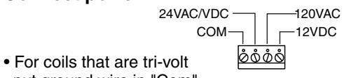
- put ground wire in "Com". Put power wire in correct voltage slot on strip.
- For coils with two wires attach one wire to ground. Attach one wire to power. Coil is non-polarized so it doesn't matter which wire is attached to which.
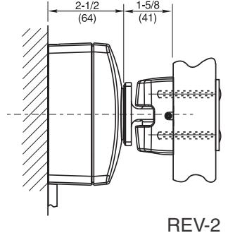
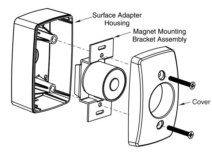
- 4 Attach cover & magnet mounting bracket assembly to Surface Adapter Housing.
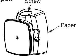
- 5 Loosen contact plate adjustment screw.
6 Remove paper.
- 7 Turn power on.
-
8 Place armature flat on coil. Make sure round solenoid is completely covered by contact plate.
- ** If coil cannot be energized yet, hand hold contact plate on magnet and complete next steps.
- 9 Open door against armature on wall.
- 10 Tighten contact plate on armature.
- 11 Pull door away leaving mounting template sticking to face of door.
CAUTION: Nicks and scratches on the metal ring of the coil will lessen or diminish the holding force of the magnet. Do not remove protective cap until ast steps of installation.
12 Select Thru Bolt or Surface mounting option.
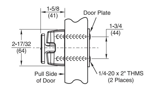
Thru Bolt Mounting
Recommended for Hollow Metal, Hollow Core or Composite Type Wood Doors
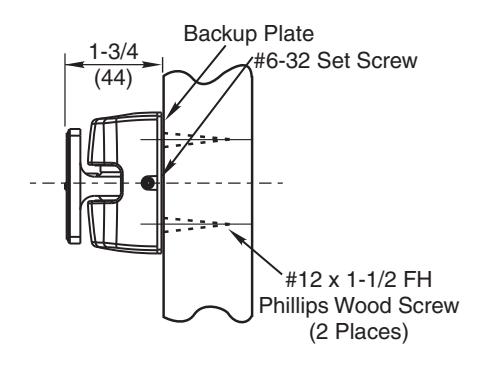
Surface Applied Concealed Mounting Recommended for Solid Wood Doors Only
13 Affix to door.
REV-2