Installation Instructions for Low Profile Mortise Locks
Open the original PDF document
View PDF

Installation Instructions Profile Series v.G1 Mortise Lock

Copyright © 2009, Sargent Manufacturing Company, an ASSA ABLOY Group company. All rights reserved. Reproduction in whole or in part without the express written permission of Sargent Manufacturing Company is prohibited.


| Table of Contents | Page | |
|---|---|---|
| 1 | Warning | |
| 2 | General Description | 1 |
| 3 |
Specifications
|
1 |
| 4 |
Features
|
1 |
| 5 | Parts Breakdown | 2-3 |
| 6 |
Installation Instructions
|
4-9 |
| 7 |
Operational Check
|
10 |
| 8 | Installation of the RF Technology Lock (G1-TU, G1-TA, G1-TP)10 |


Warning Warning: Changes or modifications to this unit not expressly approved by the party responsible for compliance could void the user's authority to operate the equipment.
This device complies with Part 15 of the FCC Rules. Operation is subject to the following two conditions: (1) this device may not cause harmful interference, and (2) this device must accept any interference received, including interference that may cause undesired operation.
Note: This equipment has been tested and found to comply with the limits for a Class B digital device, pursuant to Part 15 of the FCC Rules. These limits are designed to provide reasonable protection against harmful interference in a residential installation. This equipment generates, uses and can radiate radio frequency energy and if not installed and used in accordance with the instructions, may cause harmful interference to radio communications. However, there is no guarantee that the interference will not occur in a particular installation. If this equipment does cause harmful interference to radio or television reception, which can be determined by turning the equipment off and on, the user is encouraged to try to correct the interference by one or more of the following measures:
- • Reorient or relocate the receiving antenna
- • Increase the separation between the equipment and receiver
- • Connect the equipment into an outlet on a circuit different from that to which the receiver is connected
- • Consult the dealer or an experienced TV technician for help
This Class B digital apparatus complies with Canadian ICES-003.
Cet appareil numérique de la classe B est conforme avec la norme NMB-003 du Canada.
Warning ! To comply with "Fire Listed" doors, the batteries must be replaced with alkaline batteries only.

General Description 2
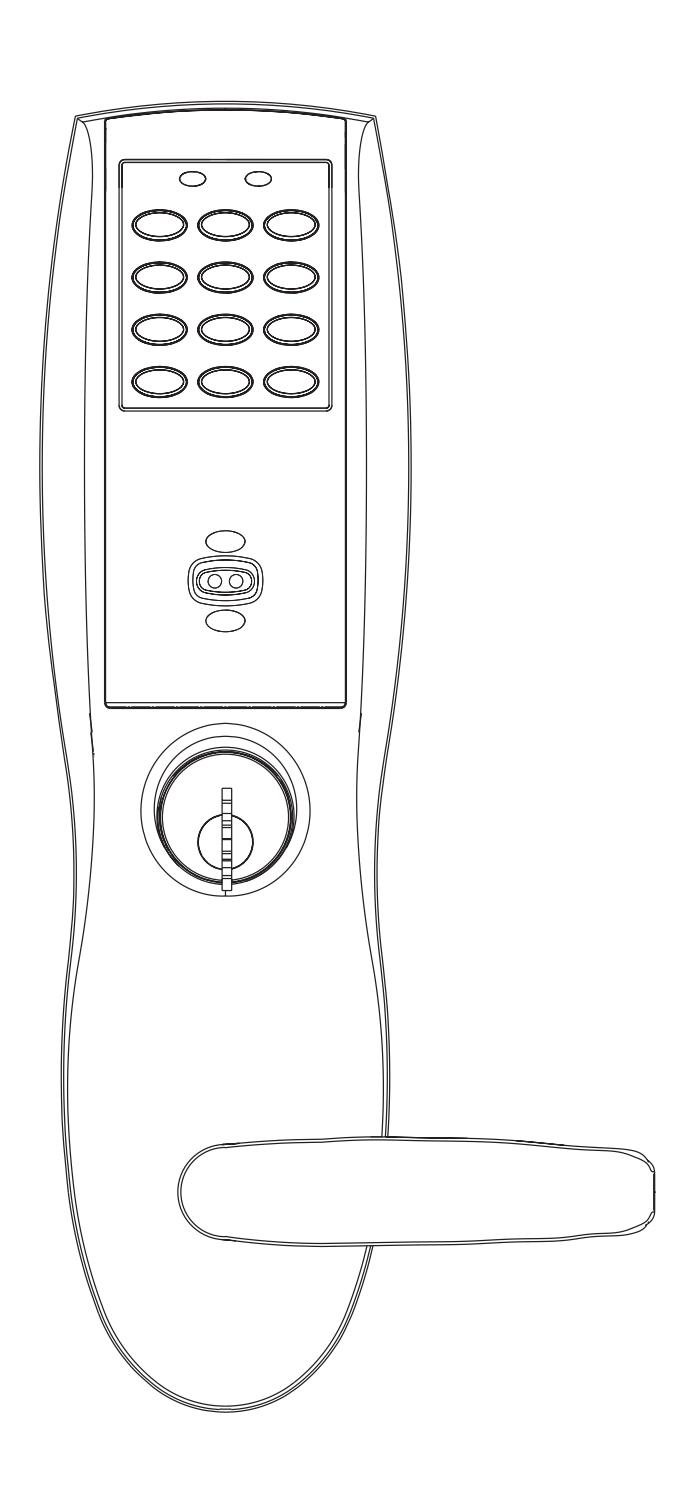
The SARGENT Profile v.G1 Mortise Lock is designed for areas which require stand alone authorized entry. It is a self-contained microprocessor-controlled keypad with non-volatile memory. The keypad will hold a total of 100(LK)/2000 (G1-LU, G1-PK, G1-PA, G1-TU, G1-TP, G1-TA) different user codes. User codes "01" & "02" are utilized for Master and Supervisory Codes, respectively.
This product is operated by six (6) "AA" alkaline batteries. SARGENT mortise locks are designed with quality components to provide high security, performance and durability.
Specifications 3
- Latch Stainless steel
- Deadbolt Stainless steel
- Guardbolt Stainless steel, non handed
- Handed Easily field reversible without disassembling the lock body
- Case 12 gauge heavy duty wrought steel
- Outside lever controlled by any combination of keypad, Proximity or RF Technology
- Inside lever retracts latch and deadbolt
- Locks furnished for 1-3/4" doors. Can be furnished for other door sizes upon request. Consult factory
- U.L. Listed (3 hr.)
Features 4
- Low battery alert–4 chirps after code entry
- • External remote "request to enter" connector
- Master, Emergency or Supervisory code will unlock door when low battery has expired
- • Programming done at the keypad (Except G1-PA & G1-TA) or with a PDA using SofLink Plus software and a PC
- Entry of three wrong User Codes disables all codes for ten seconds. Yellow LED on solid
- Last 15 transactions can be output to portable printer via infrared link (LK Only)
- • Last 2000 (Except LK) transactions can be output to a PC via a PDA and SofLink™ Plus software


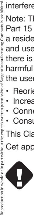
Parts Breakdown


27/28

Parts Breakdown (Continued) 5
| ITEM | PART No. | DESCRIPTION | REQ'D |
|---|---|---|---|
| 1 | 82-4190 | Outside Escutcheon with Cylinder Hole and Key Pad, or Key Pad/Prox (G1-LU, G1-PK, G1-TU, G1-TP)1 | |
| 82-4191 | Outside Escutcheon without Cylinder Hole and Key Pad or Key Pad/Prox (G1-LU, G1-PK, G1-TU, G1-TP)1 | ||
| 82-4192 | Outside Escutcheon with Cylinder Hole and Prox Only (G1-PA, G1-TA) | 1 | |
|
82-4193
82-0493 |
Outside Escutcheon without Cylinder Hole and Prox Only (G1-PA, G1-TA)
Outside Escutcheon Housing Only without Cylinder Hole |
1
1 |
|
| 82-0495 | Outside Escutcheon Housing Only with Cylinder Hole | 1 | |
| 52-2432 | Keypad/Proximity Bezel Assembly w/ Harness (LK) | 1 | |
| 52-2706 | Proximity Only Bezel Assembly with Harness (G1-PA, G1-TA) | 1 | |
| 52-2704 | Key Pad/Proximity Bezel Assembly with Harness (G1-LU, G1-PK, G1-TU, G1-TP) | 1 | |
| 2 |
82-3837
82-3838 |
Inside Escutcheon with Thumb Turn and 100 User Controller (LK)
Inside Escutcheon without Thumb Turn and 100 User Controller (LK) |
1
1 |
| 82-4182 | Inside Escutcheon with Thumb Turn and 2000 User Controller (G1-LU) | 1 | |
| 82-4183 | Inside Escutcheon without Thumb Turn and 2000 User Controller (G1-LU) | 1 | |
| 82-4184 | Inside Escutcheon with Thumb Turn Prox/Key Pad Controller (G1-PA, G1-PK) | 1 | |
| 82-4185 | Inside Escutcheon without Thumb Turn Prox/Key Pad Cont. (G1-PA, G1-PK) | 1 | |
|
82-4186
82-4187 |
Inside Escutcheon with Thumb Turn & 2000 User Controller with RF Technology (G1-TU)
Inside Escutcheon Less Thumb Turn & 2000 User Controller with RF Technology (G1-TU) |
1
1 |
|
| 82-4188 | Inside Escutcheon with Thumb Turn & Keypad/Prox or Prox Only Controller (G1-TA, G1-TP) | 1 | |
| 82-4189 | Inside Escutcheon Less Thumb Turn & Keypad Prox or Prox Only Controller (G1-TA, G1-TP) | 1 | |
| 82-0492 | Inside Escutcheon Housing Only without Thumb Turn | 1 | |
| 82-0494 | Inside Escutcheon Housing Only with Thumb Turn | 1 | |
| 52-2440 | 100 (LK) User Key Pad Controller Assembly | 1 | |
|
52-2783
52-2784 |
2000 (G1-LU) User Controller Assembly
2000 User (G1-PA, G1-PK) Controller Assembly |
1
1 |
|
| 52-2786 | 2000 User Keypad/Prox Controller Assembly w/ RF Technology (G1-TA, G1-TP) | ||
| 52-2785 | 2000 User Keypad Controller Assembly w/ RF Technology (G1-TU) | ||
| 3 |
52-0170
52-2509 |
Battery Cover
Battery Cover – RF Technology (G1-TU,G1-TP, G1-TA) |
1 |
| 4 | 01-1212 | Security Screw | 1 |
| 5 | 01-0297 | Security Tool | 1 |
| 7 | 82-0507 | Thumb Turn | 1 |
| 8 | 77-0772 | Spindle (Thumb Turn) | 1 |
| 9 | 01-0844 | Washer (Thumb Turn) | 1 |
| 10 | 01-0543 | Spring Grip Fastener (Thumb Turn) | 1 |
| 11 | 77-0168 | Through-bolts #8-32 x 1 7/8" Flat Head Screw | 2 |
| 12 | 52-0033 | Fire Stop Plate | 1 |
| 13 | 01-1500 | Fire Stop Screws #8 x 1/2" Type "AB" Phillips Pan Head Self Tap | 2 |
| 14 | 82-3088 | Inside Spindle Adapter & Plate Assembly | 1 |
| 15 | 01-1495 | Screw #8-32 x 1/2" | 2 |
| 16 | 82-0368 | Inside Spindle/Outside Spindle | 2 |
| 17 | 82-0347 | Inside Spring/Outside Spring | 2 |
| 18 | 82-0081 | Face Plate no Dead Bolt | 1 |
| 19 | 82-0084 | Face Plate with Dead Bolt | 1 |
|
20
21 |
01-1028
01-2299 |
Face Plate Screws Machine 8-32 x 1/4"
Lock Body Screws/Wood Door #12 x 1 1/4" |
2
2 |
| 22 | 01-1019 | Lock Body Screws/Metal Door 12-24 x 1/2" | 2 |
| 23 | 82-0184 | Cap Nut | 1 |
| 24 | 01-0079 | Washer | 2 |
| 25 | 82-3082 | Plate Assembly | 1 |
| 26 | 81-0723 | Post | 2 |
| 27 | 01-1472 | Lever Handle Screw, A, E & F Lever | 1 |
| 28 | 01-1174 | Lever Handle Screw, B, J, L, P & W Lever | 1 |
| 29 | Reference Profile Series catalog for available lever handles | ||
| 30 | |||
| 31 | 82-3732 | Lockbody Assembly (with deadbolt) (8276 & 8277) | 1 |
| 82-3733 | Lockbody Assembly (without deadbolt) (8278 & 8279) | 1 | |
| 32 | 01-0803 | Battery Alkaline ("AA" cell) | 6 |
| 33 | 52-0253 | Battery Keeper | 1 |
| 52-0344 | Battery Keeper – RF Technology (G1-TU, G1-TP, G1-TA) |

4/01/09 Copyright © 2009, Sargent Manufacturing Company, an ASSA ABLOY Group company. All rights reserved. Reproduction in whole or in part without the express written permission of Sargent Manufacturing Company is prohibited.


ASSA ABLOY
Profile Series v.G1 Mortise Lock
6 Installation Instructions
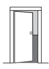
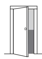
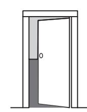
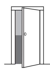
Verify Hand and Bevel of Door
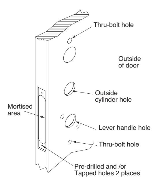
Step #1 – Door Preparation
Before Starting
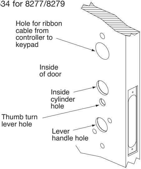
Prep door according to Instruction Sheet A7454 and appropriate template:
Wood door - A7457
Metal door - 4533 for 8276/8278


(

ASSA ABLOY
Connector
End Cap
Connector
and wires
Profile Series v.G1 Mortise Lock
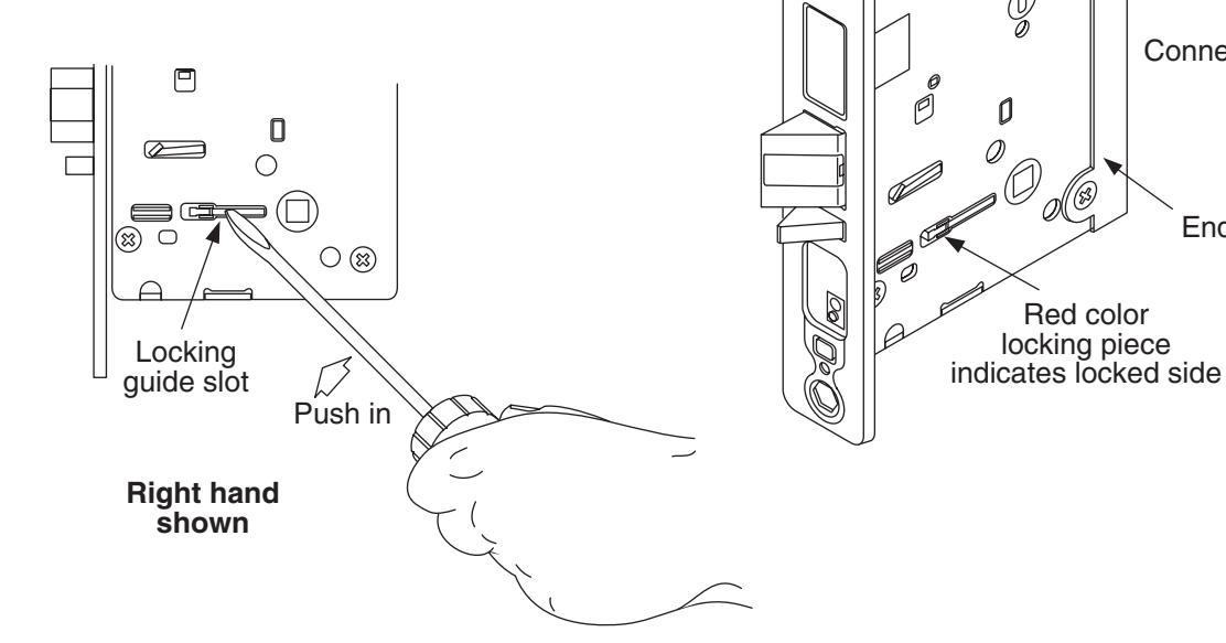
Step #2 – How to Reverse Lock Hand
If it is necessary to change hand of locking piece:
- 1. Turn lockbody to side NOT marked with RED locking piece.
- 2. Insert blade of common screwdriver into locking piece slot.
- 3. Push locking piece toward front of lockbody and rotate until RED shows.
- 4. RED indicates locked (outside) side.
- 5. Wire harness MUST exit thru non-cylinder side.
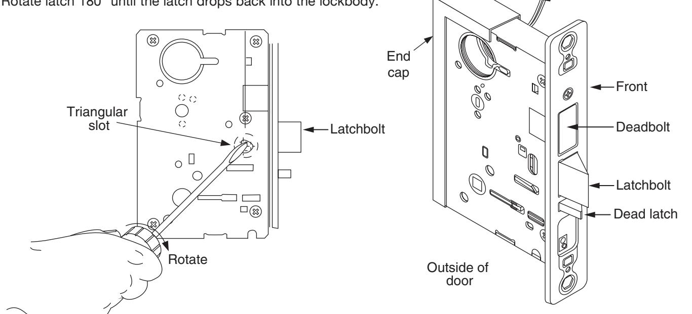
If it is necessary to change hand of latch:
1. Insert blade of common screwdriver into triangular slot behind latch.
2. Rotate screw driver and push latch out until back of bolt clears lockbody front.

ASSA ABLOY, the global leader in door opening solutions
A7454C• 800-810-WIRE (9473) • www.sargentlock.com

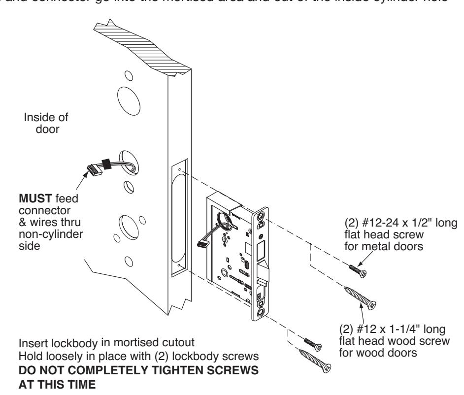
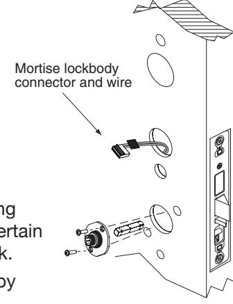
Step #3 – Lockbody Installation
Wires and connector go into the mortised area and out of the inside cylinder hole
Step #4 – Attach Fire Stop Plate
NOTE: Required for 12- fire rated doors.
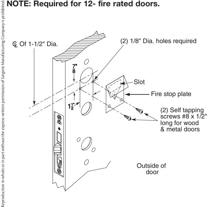
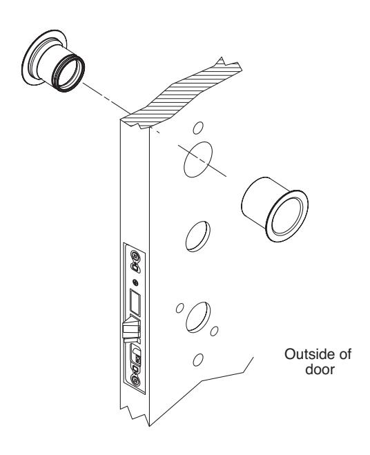
Non Fire Rated Exterior Doors-Install Weather Conduit (P/N 52-2847) as shown below
6 800-810-WIRE (9473) • www.sargentlock.com • A7454C
4/01/09 Copyright © 2009, Sargent Manufacturing Company, an ASSA ABLOY Group company. All rights reserved.

ASSA ABLOY
Keypad ribbon
Profile Series v.G1 Mortise Lock
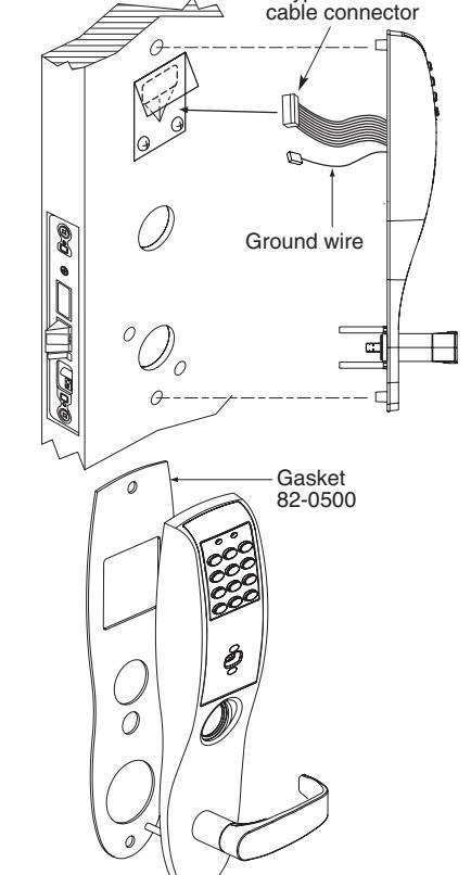
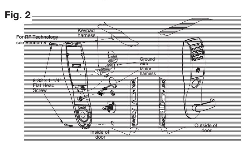
Step #5 - Installation of Outside/Inside Escutcheon & Lever Assembly
NOTE: For exterior applications, gasket (82-0500) should be used to seal between escutcheon and outside door surface
- 1A. For 12- fire rated devices, feed keypad ribbon cable connector and ground wire from outside of door through gasket and fire stop plate hole
- 1B. For non-12- exit devices, feed keypad ribbon cable connector and ground wire through gasket then through hole in door
- With outside lever horizontal, insert mounting posts through door and lock body. Make certain the lever spindle is properly engaged in lock.
- 3 Secure inside adapter and plate assembly by threading screws into mounting posts of outside lever assembly
- Tighten retaining nut by hand, back off slightly until star pattern lines up with square lever assembly corners
- Insert spindle into square hole of adapter plate
Ground tab (E3)
Remote
unlock/power connector

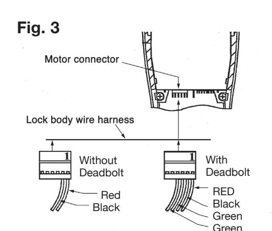
- Connect ground wire to terminal E3 (Ref. Fig. 1), keypad ribbon cable connector to controller (Ref. Fig. 2), and ET motor harness to motor connector (Ref. Fig. 3).
- Place extra wire inside door hole or outside escutcheon being careful not to pinch wires
NOTE: Connectors go on only one way, do not offset connector and be sure they are completely seated
Insert #8-32 x 1-1/4" screws through inside escutcheon and thread into outside escutcheon. Straighten (Ref. Fig. 2) escutcheons and tighten securely.
NOTE: For RF Technology versions (G1-TU, G1-TP, G1-TA) refer to Section 8 to install through bolt screws.
4/01/09
ASSA ABLOY, the global leader in door opening solutions
A7454C• 800-810-WIRE (9473) • www.sargentlock.com
Fig.
Groundwire
Motor

ASSA ABLOY
Profile Series v.G1 Mortise Lock
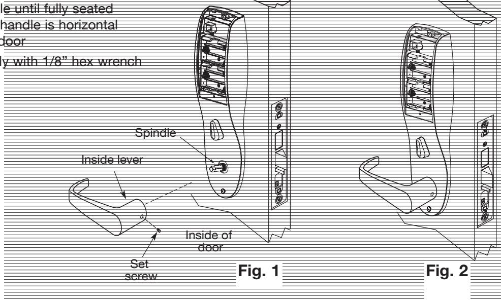
Step #7 - Installation of Inside Lever and Outside Cylinder
- 1. Put the turn lever in the horizontal position (Ref. Fig. 1).
- 2. Slide lever handle onto spindle until fully seated (as shown in Fig. 2). Be sure handle is horizonta and facing to the rear of the door
- 3. Tighten the set screw securely with 1/8" hex wrench
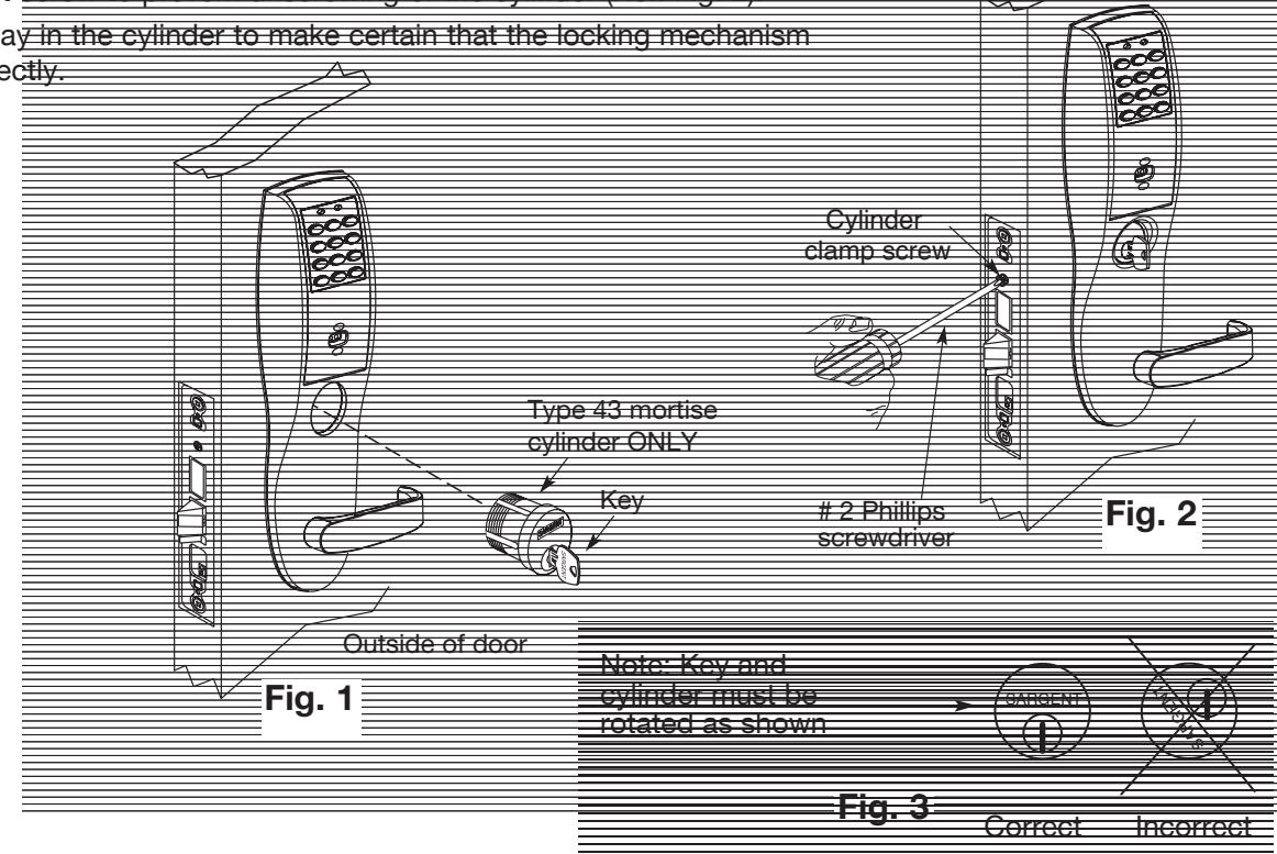
Step #8 – Installation of Cylinder
- 1. Align cylinder (as shown in Fig. 1)
- 2. Screw cylinder into lockbody unit (Ref
- 3. Tighten the set se
- 4. Turn the keyway in the functions correct

ASSA ABLOY
Profile Series v.G1 Mortise Lock
Step #9 – Battery Installation/Application of Front Plate
- 1. Tighten lockbody screws (Ref. Fig. 1)
- 2. Attach front plate with (2) flat head screws
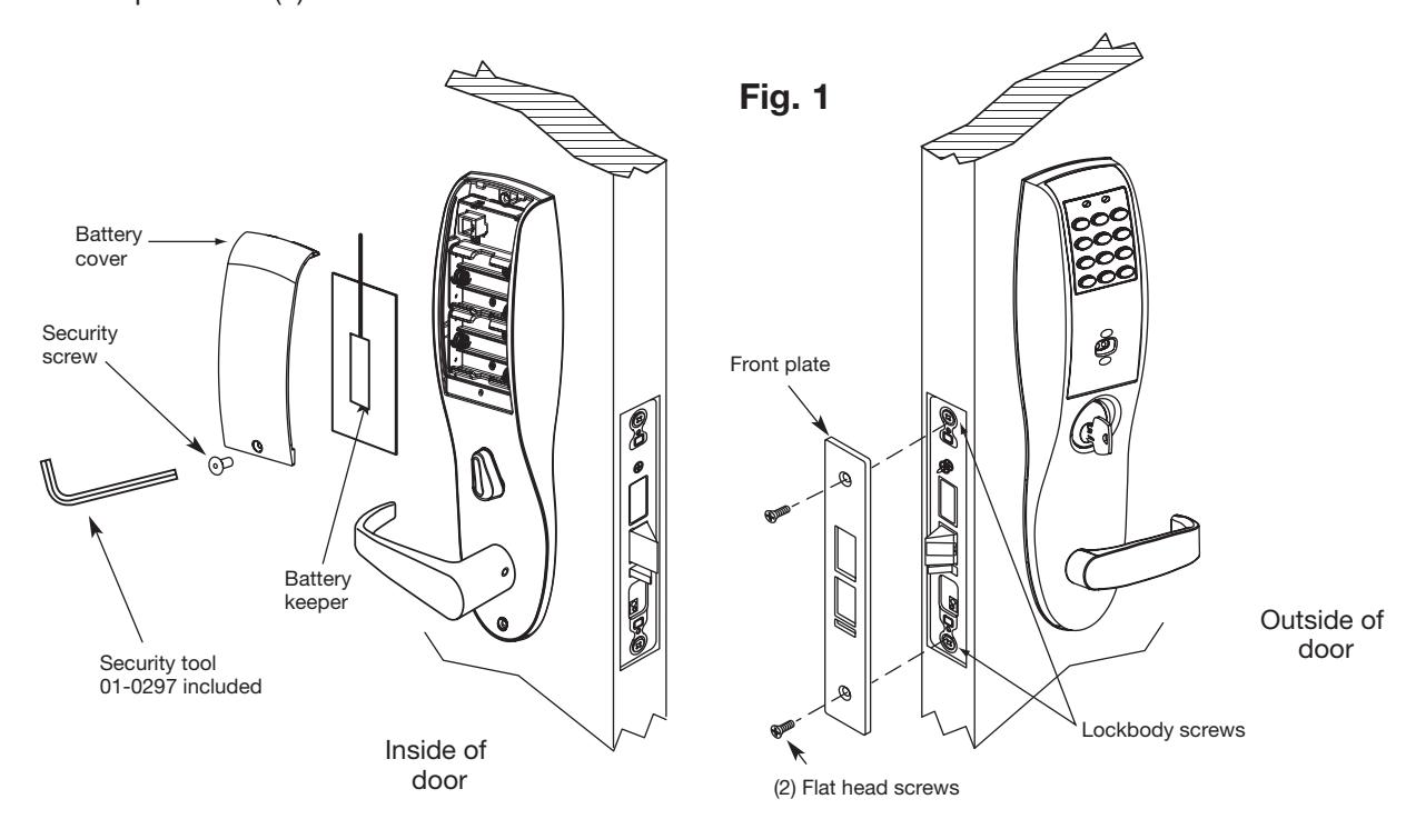
- 2. Place (6) "AA" batteries* into the compartment being careful to align polarity properly (Ref. Fig. 2).
- 3. Install battery keeper clip by inserting tabs into bottom slots. To remove keeper, pull on top tab (Ref. Fig 3).
(
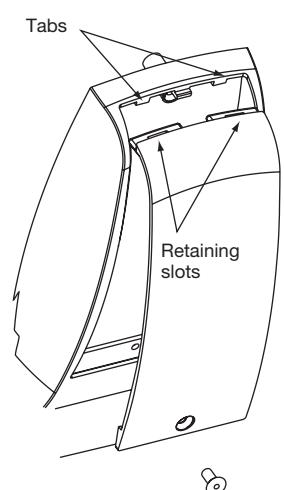
4. Attach battery cover to inside escutcheon making sure to line up tabs with retaining slots in battery cover. Secure with security screw (Ref. Fig. 4).
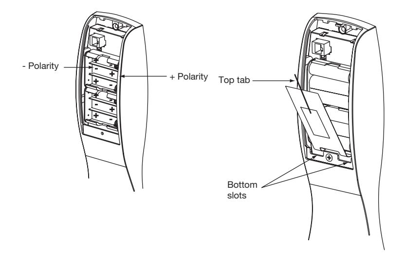
Fig. 2 Fig. 3
8
Fig. 4
A7454C• 800-810-WIRE (9473) • www.sargentlock.com
(
(
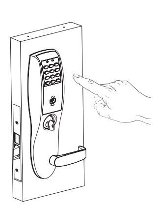
Operational Check 7
For devices with cylinders:
- 1. Insert key into cylinder and rotate (There should be no friction against lock case, wire harness or any other obstructions – refer to Section 6, Step 8 if harness friction exists.
- 2. The key will retract the latch, key should rotate freely
- 3. If the deadbolt is thrown, the key will retract both the deadbolt and the latch
- 4. Inside lever retracts latch and deadbolt (if provided)
- 5. Enter 1234* to unlock outside lever handle and retract latch and deadbolt (if provided)
- 6. If lock is prox only (G1-PA) or RF Technology with prox (G1-TA) refer to keypad programming instructions (A7716) to program lock using SofLink Plus™ software.
Installation of RF Technology Lock 8
The RF Technology Lock (G1-TU, G1-TA, G1-TP) is installed as described in sections 1-7 with the following exceptions:
- Installation of the top through-bolt screw
- Removal process for the battery keeper
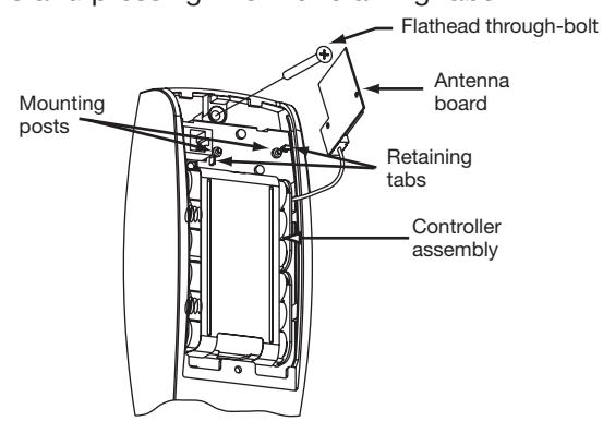
A. Installation of the top through-bolt screw:
The antenna board must be carefully moved to access the upper through-bolt screw. Care should be taken to prevent damage to the antenna retaining tabs during this process.
Press the two tabs away from the antenna board and lift the board off the mounting posts. Insert the flat head through-bolt and secure the escutcheon in place. After tightening the top through-bolt, replace the antenna board by placing it on the mounting posts and pressing into the retaining tabs.
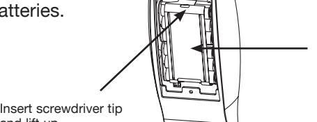
B. Removal procedure for the Battery Keeper:
To remove the battery keeper, a flat bladed screwdriver or similar tool must be used.
Insert the screwdriver into the slot at the top of the battery keeper, lift up and pull the top of the keeper away from the batteries.
To install, insert the tabs on the bottom of the keeper into the battery compartment slots and press the keeper tightly against batteries.
Battery Keeper
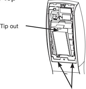
Keeper tabs
4/01/09 Copyright © 2009, Sargent Manufacturing Company, an ASSA ABLOY Group company. All rights reserved. Reproduction in whole or in part without the express written permission of Sargent Manufacturing Company is prohibited.
10 800-810-WIRE (9473) • www.sargentlock.com • A7454C
and lift up
