Installation Instructions for Freewheeling FE Escutcheon Trim
Open the original PDF document
View PDFINSTALLATION INSTRUCTIONS FOR 8200 Lever with Freewheeling Escutcheon Trim FE
FOR ASSISTANCE, CALL SARGENT AT 1-800-727-5477 or www.sargentlock.com
Patent pending and/or patent www.assaabloydss.com/patents
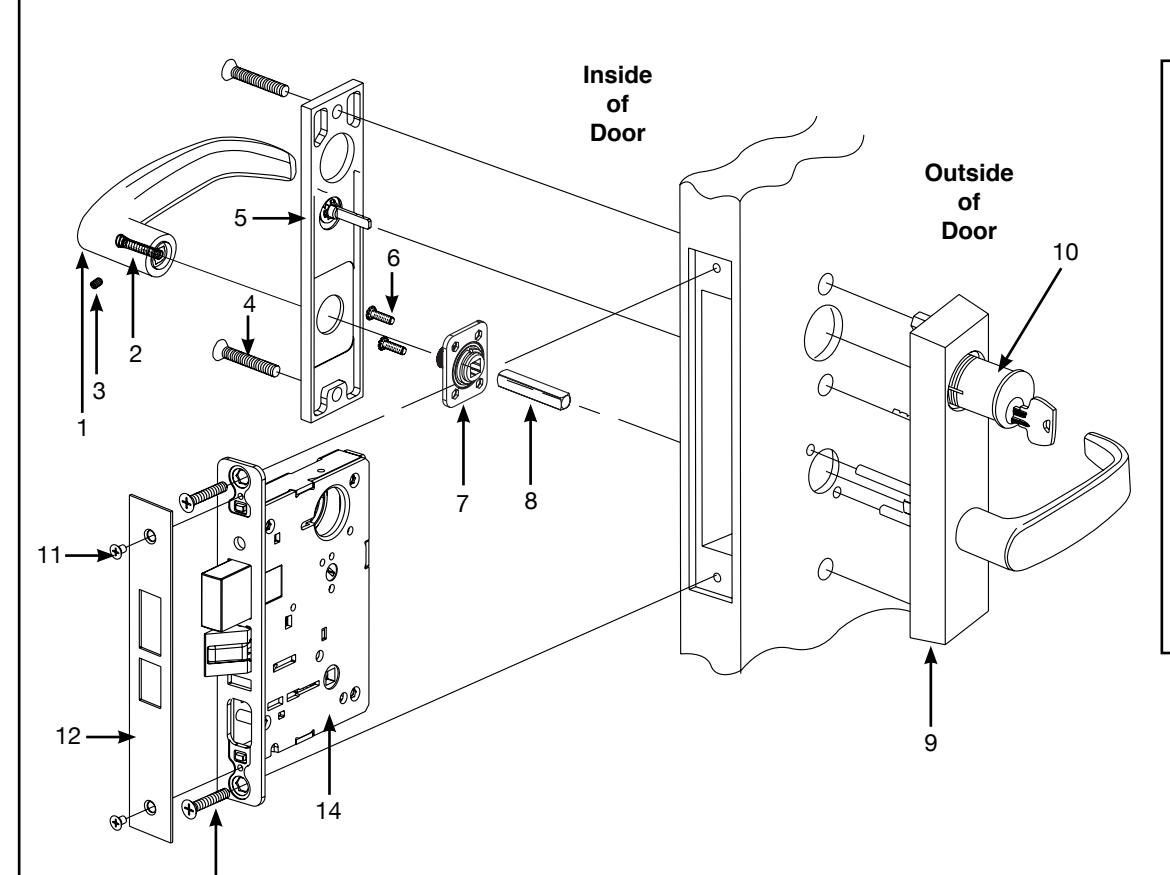
Parts List Description
- 1. Inside Lever
- 2. Spring
- 3. Set screw
- 4. Through-bolt Screws (2) (1/4" - 20 x 1-3/4)
- 5. Inside Escutcheon Plate
- 6. Screws & Lockwashers (2) (#8-32 x 5/8")
- 7. Adapter & Plate Assy.
- 8. Lever spindle
- 9. Outside Escutcheon Assembly
- 10. Cylinder
- 11. Screws (2) (#8-32 x 1/4")
- 12. Front Plate
- 13. Lockbody screws (2) (#12 x 1-1/4")
- 14. Lockbody
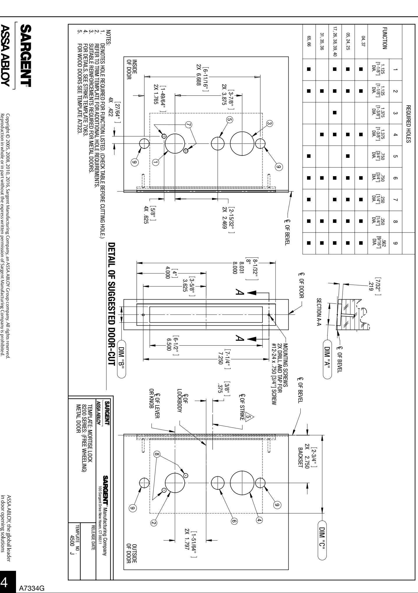
25 Function Shown — For hole locations of other functions, see template page 4
1 2
13
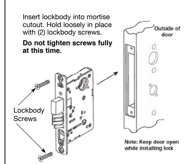
Install Lockbody Outside Escutcheon Assembly
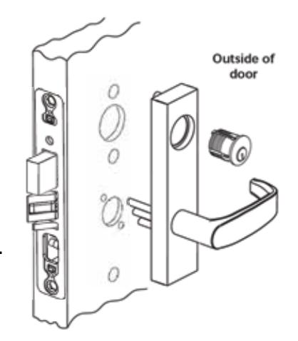
A. With outside lever horizontal, carefully insert the mounting posts through the door and lockbody. Make sure the spindle is properly engaged in the lock. Outside escutcheon assembly should be flush with door surface.
If cylinder is not included in this function, proceed to step 3.
B. Screw cylinder into lockbody until flush with escutcheon face.
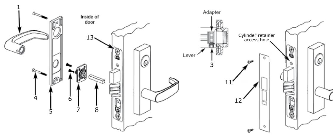
Inside Adapter & Plate Assembly 3
- A. Slide spindle (8) into lockbody hub
- B. Slide adapter & plate assembly (7) over spindle and secure with two #8-32 screws (6) (do not tighten)
- C. Tighten lockbody screws (13) on edge of the door
- D. Tighten both #8-32 (6) screws, securing adapter & plate assembly
- E. Position inside Escutcheon (5) and secure with two 1/4-20 x 1-3/4" screws (4)
- F. Place inside lever (1) horizontally onto lever spindle (8). Hold lever firmly against the escutcheon.
- G. Use the 1/8" Allen wrench to tighten the set screw (3) securely. Set screw should seat in the groove of the inside adapter (7).
- H. Pull on lever to verify set screw is seated properly.

- I. With the cylinder flush to the escutcheon face, rotate cylinder to make the keyway vertical. This ensures that the cylinder retainer fork will line up with the notch on the side of the cylinder.
- J. Secure the cylinder with a #2 Phillips screw driver, using the cylinder retainer access hole.

L. Secure Outside Front (12) with two #8-32 screws (11) to the lockbody.
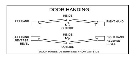
How to Change Hand of Lock
Note: Red surface of locking piece must face secure side of door. To rotate locking piece:
- 1.Position lockbody with red surface of locking piece visible
- 2.Insert blade type screwdriver into locking piece slot to rotate locking piece
- 3.Push locking piece toward back of lock body and rotate 180° until RED surface shows on opposite side
Note: Functions 04, 06, 13, 17 and 31 require the following, before the locking piece can be rotated:
- (a) Remove the Green catch screw
- (b) Rotate hub to make straight
- (c) Rotate locking piece for required hand
- (d) Red surface faces locked side of door
- (e) Rotate hub to the original 45 degree position as shown on lock case
- (f) Reinstall the Green catch screw
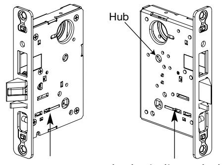
Locking piece slot
Red color indicates locked side of door
Note: Beveled surface of latch must face strike. The deadlatch is self adjusting. To change hand of latch:
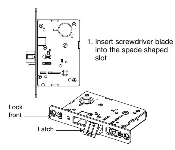
2. Rotate screwdriver 90º to push latchbolt out of the lock case, until back of latchbolt clears lock front. Then rotate latchbolt 180º allowing it re-enter the lockbody.
(Note: Latch can not be unscrewed)
Changing Hand Of Trim
in door opening solutions
ALWAYS WEAR EYE PROTECTION WHILE WORKING
- SARGENT
- Loosen screw (1) and remove interlocking assembly (2). See Figure A.
ASSA ABLOY
- 2. Unscrew the lower through-bolt stud (11) with a 3/8" wrench. Remove mounting plate (6) and mounting posts. Switch mounting posts (7) so they occupy the opposite positions on the mounting plate (6)
- 3. Note the original position of the extension spring (16) and lower plate (9) in the escutcheon (14). Unhook the extension spring from pin (13).
- 4. Remove spring (16), lower plate (9) and locking hub (8) assembly together.
- 5. Detach extension spring (16) from lower plate (9) and locking hub assembly (8). Flip lower plate on locking hub assembly spindle so that the spring hole is on the opposite side. Reattach hook end of spring to lower plate.
- 6. Unscrew cap screw w/spacer (12) using 5/32" Allen wrench. Move to opposite hole and tighten firmly.
- 7. Rotate lever to position shown in Figure E for desired hand.
- 8. Tighten retaining nut (10) firmly by hand and then back off one notch until pattern shown in Figure C appears.
- 9. Attach bottom of spring (16) (closed loop) to pin (13). Hold lever horizontal while inserting locking hub assembly (8) and lower plate (9) into retaining nut (10).
- 10. Refer to Figure E: Position hub (4) for required function and hand, checking that spindle (5) is vertical. Note position of interlocking assembly Hook when positioning hub. Reposition spindle as shown in Figure D if necessary.
- 11. Place the interlocking assembly (2) into the escutcheon and attach the bottom hook to the locking hub (8) as shown in Figure B. Secure in place with screw (1). Caution: Check that locking hub (4) moves freely by rotating the hub spindle (5). If not, check that bottom hook is engaged in locking hub (8).
- 12. Insert and secure mounting plate and mounting posts to escutcheon with lower through-bolt stud (11).

1-51/64"
OF DOOR OUTSIDE
4500 J