Installation Instructions for DL Lever Lock
Open the original PDF document
View PDFInstallation Instructions

DL Series Tubular Lock
1 Tools Required
- #2 Phillips screwdriver
- T20 sized security bit
- 1/8" drill bit
- 2-1/8" drill bit
- 1" drill bit
- Right angle square (square roses)
Product Components
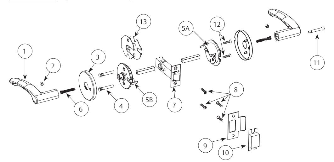
| ltem | Description | Qty |
|---|---|---|
| 1 | Lever | 2 |
| 2 | Set Screw | 2 |
| 3 | Rose Assembly | 2 |
| 4 | Mounting Post | 2 |
| 5A | Inside Spring Housing | 1 |
| 5B | Outside Spring Housing | 1 |
| 6 | Lever Springs | 2 |
| 7 | Latch | 1 |
| 8 | T-Strike Screw Pack | 1 |
| 9 | Standard T-Strike | 1 |
| 10 | Wrought Box Strike | 1 |
| 11 |
Push Button
(Privacy Function Only) |
1 |
| 12 | Mounting Post Screw Pack | 1 |
| 13 |
Fire Clip
(Required for fire-rated doors) |
1 |
Note: Refer to DL Series Parts Manual for Part
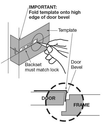
Door and Frame Preparation
- Hollow Metal Doors should be properly reinforced for lock support. If support is not provided, contact door manufacturer.
- For door preparations, use template A6305 (Except for single and double lever pull functions (DLU93 / DLU94) which use template A7931).
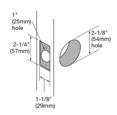
1. Mark and Drill Holes
2. Final Door Prep
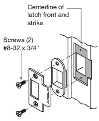
3. Frame Preparation
DL Series
Tubular Lock
Installation Instructions

4 Installation
a Passage (DLU15) and Privacy (DLU65) Functions
IMPORTANT
For proper installation, the spring housing assembly with sticker should have arrow pointing towards latchbolt and be legible during installation. See Figure 1.
-
1. Install latch using (2) #8-32 x 3/4" screws. Install loosely; tighten after step #5.
- a. For DLU65 privacy function, the threaded hole on locking piece must be toward the inside of the door. See Figure 2.
- 2. Slide outside assembly into bore.
- 3. Install inside mounting plate assembly using (2) #8-32 x 3/4" screws. Note location for set screw, see Figure 3.
- 4. Install rose onto spring housing assembly. See page 4 if Square Roses.
-
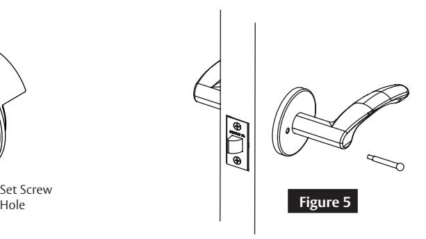
5. Install lever onto spindle. Insert set screw into hole in lever and tighten.
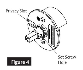
- a. If lever set screw does not align with the threaded hole in the spring housing assembly, remove spindle and rotate the hub 180 degrees. Ensure the set screw orientation in the hub is opposite the privacy slot in the housing, see Figure 4.
- 6. For DLU65 privacy function, install push button. See Figure 5.
Screws (2) #8-32 x 3/4" Figure 1 Install first for fire rated option only.
Locking Piece
b Communicating (DLU15-3) Function
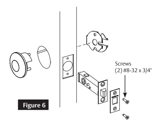
- 1. Install latch using (2) #8-32 x 3/4" screws. Install loosely; tighten after step #5.
- 2. Slide blank outside rose assembly into bore, see Figure 6.
- 3. Install inside spring housing assembly, rose and lever same as #3, 4 & 5 above.
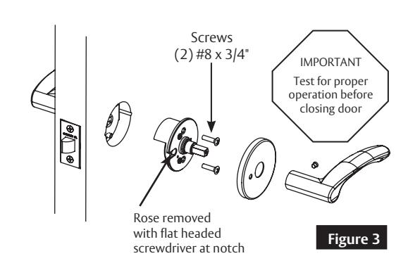
Figure 2
1-800-727-5477 • www.sargentlock.com A7858H 01/23
DL Series
Tubular Lock
Installation Instructions

4 Installation, Continued.
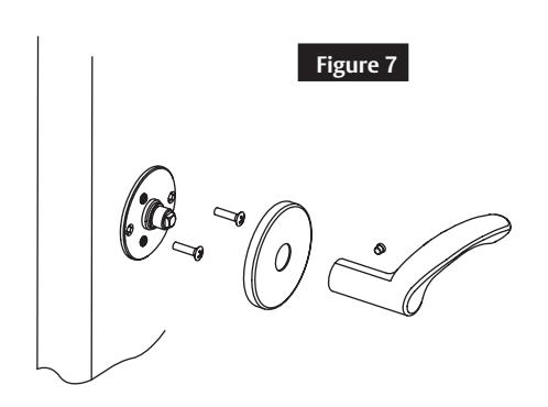
c Single Lever Pull (DLU93) Function
- 1. Install inside mounting plate assembly using (2) #8-32 x 3/4" screws. Note location for set screw.
- 2. Install rose onto spring housing assembly. See page 4 if Square Roses.
- 3. Install lever onto spindle. Insert set screw into hole in lever and tighten. See Figure 7.
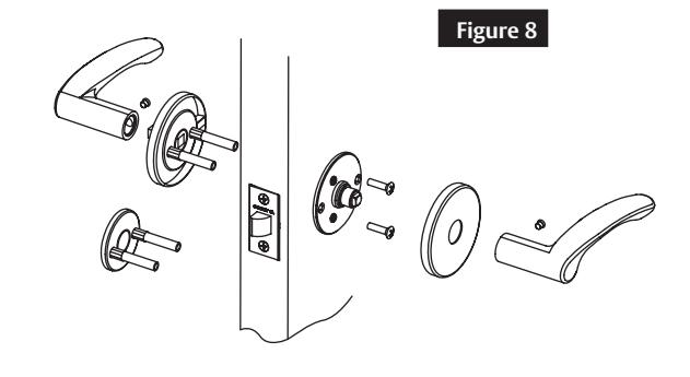
d Through-bolted Single Lever Pull (TB-DLU93) and Double Lever Pull (DLU94) Functions
- 1. Install through-bolt assembly from outside.
- 2. Install inside mounting plate assembly using (2) #8-32 x 3/4" screws. Note location for set screw.
- 3. Install rose onto spring housing assembly. See page 4 if Square Roses.
- 4. Install lever onto spindle. Insert set screw into hole in lever and tighten. Repeat process for outside lever (94 Function only). See Figure 8.

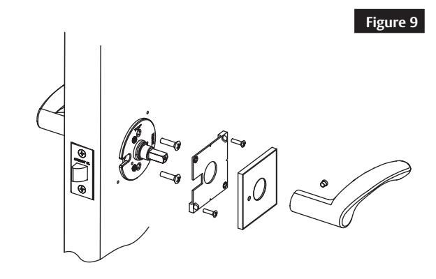
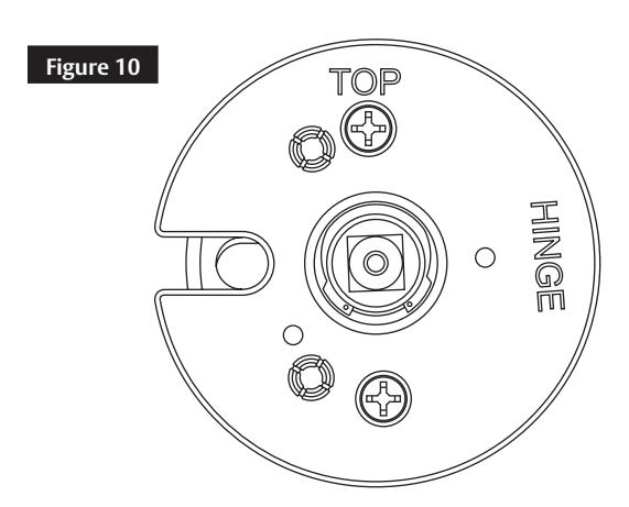
5 Square Rose Installation (Figure 9)
- 1. Install latch, outside assembly and inside spring housing assembly per function.
- 2. Position square mounting plate over spring housing, See Figure 10.
- 3. Drill two centered pilot holes for the #6-32 mounting screws in the upper right and lower left portions of the square mounting plate.
- 4. Loosely attach mounting plate to both sides of the door with screws.
- 5. Square top surface of mounting plate to edge of door. a. The right angled square MUST be on the flat surface of the square mounting plate for proper leveling.
- 6. Tighten mounting screws
- 7. Press rose onto mounting plate.
- 8. Install lever onto spindle. Insert set screw into hole in lever and tighten.
Note: To level plate, place a right angle square on the flat portion of the mounting plate.
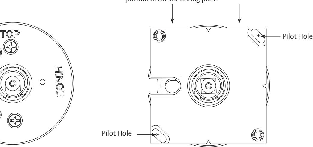
Spring Housing Square Mounting Plate
Scan with your camera on your phone to see a video of this installation step.

SARGENT Manufacturing Company 100 Sargent Drive New Haven, CT 06511 USA 800-727-5477 www.sargentlock.com

This product can expose you to lead which is known to the state of California to cause cancer and birth defects or other reproductive harm. For more information go to www.P65warnings.ca.gov.
1-800-727-5477 • www.sargentlock.com