Installation Instructions for 9-2990, 12-2990, 2990 Series FIREGUARD
Open the original PDF document
View PDFInstallation Instructions

2900 FIREGUARD® Electromechanical Closer-Holder 2990 Multipoint Hold Open with Double Lever Arm
Pull (Hinge) Side
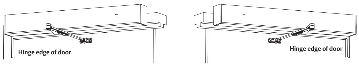
Regular Arm for Reveals Up to 7"
Models 2991, 2992, 2993

Models 2994, 2995
General Notes:
- 1. Devices are handed and must be the same hand as door.
- 2. Rod assembly portion of arm assembly increases in length for deeper reveals.
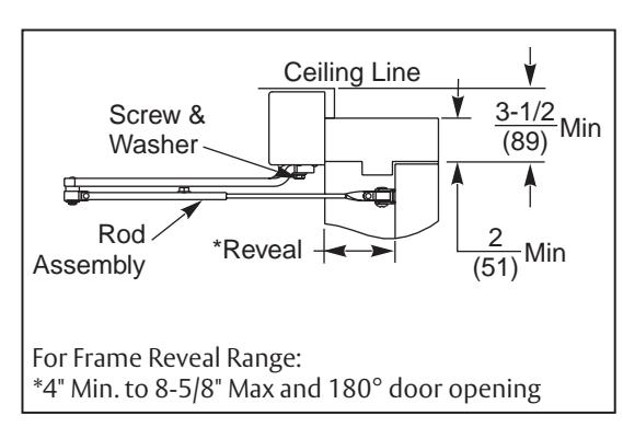
- 3. Frame face must be a minimum of 2".
- 4. Ceiling clearance must be a minimum of 3-1/2" closer.
MARNING
This product can expose you to lead which is known to the state of California to cause cancer and birth defects or other reproductive harm. For more information go to www.P65warnings.ca.gov.
INSTALLER: LEAVE INSTRUCTIONS FOR BUILDING OWNER
2990 Hold-Open Double Lever Arm/Push (Stop) Side Mounting
Installation Instructions
| TOC | Table of Contents |
|---|---|
| 1 | Install Body and Backplate Assembly 2 |
| 2 |
Install Arm
3 |
| 3 |
Final Adjustment and Regulating Procedures
4 |
| 4 |
Typical Wiring
5 |
| 5 | Optional 80- Prefix Bypass Hold Open Switch 6 |
| 6 | Template 7 |
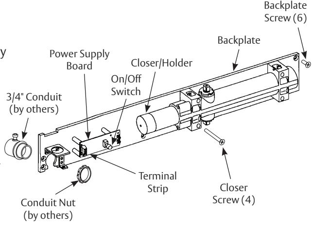
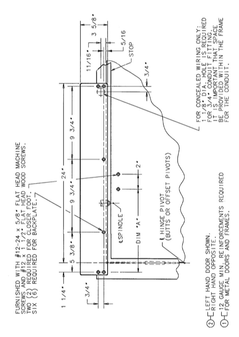
1 Install Body and Backplate Assembly
1. Use dimensions shown on provided template to prepare holes.
For concealed wire applications:
Locate and drill 1-1/8" diameter hole in the frame face for 3/4" conduit. (This is normally done at the time the frame is being installed.) Connect conduit to backplate before fastening backplate to frame. (Figure 1)
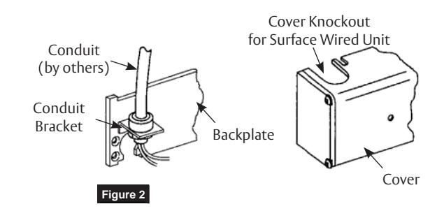
For surface wire units:
Use conduit bracket attached to backplate. (Figure 2)
- 2. Attach backplate/closer assembly to frame. Position backplate end with conduit connection away from hinge of frame. (Figure 1)
- 3. Make electrical connections (see page 5 )
- 4. Make input power connections to the power supply board as directed in Typical Wiring section.
NOTE: If electrical connections are to be made at a later date, place cover on chassis now to prevent its loss.

2
2990 Hold-Open Double Lever Arm/Push (Stop) Side Mounting
Installation Instructions
2 Install Arm
Regular Arm:
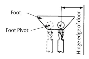
- 1. Attach foot to door with foot pivot AWAY from hinge edge of door. Move foot pivot to hole nearest hinge for additional closing power for all models. (Figure 3)
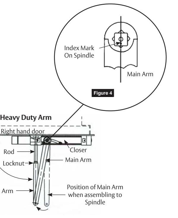
- 2. Assemble main arm to closer with index mark on spindle. Align with axis of arm. Use washer and screw. (Figure 4)
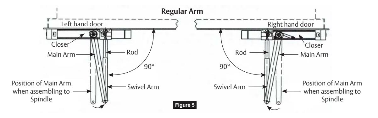
- 3. Open door and insert rectangular rod into swivel arm. Close door and tighten arm screw securely. (Figure 5)
For illustration purposes only. See template section for dimensions.

Deep Reveal Arm (Models 2994, 2995)
- 1. Assemble main arm to closer with index mark on spindle. Align with axis of arm. Use washer and screw. (Figure 4)
- 2. Adjust length of rod assembly to position rod at right angle to door. (Figure 6)
- 3. Attach the foot of the rod assembly to the door.
- 4. Tighten locknut on rod.
A7397C 09/21 1-800-727-5477 • www.sargentlock.com
Figure 6
Rod
Locknut
Swivel Arm
90°
2990 Hold-Open Double Lever Arm/Push (Stop) Side Mounting
Installation Instructions
3 Final Adjustment and Regulating Procedures
Adjust Spring Power According to Chart (Figure 7)
Turn spring adjustment nut clockwise the required number of turns to match door width as indicated in chart.
NOTE:
- • Where strong drafts exist, increase spring power as needed.
- • 351 Style door closers normally leave the factory with spring adjustment set at eight (8) turns.
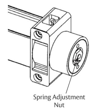
Figure 7
|
Maximum
Width of Door Interior Only |
Clockwise
Turns of Adjusting Nut |
|---|---|
| 2' 8" | 4 |
| 3' 2" | 8 |
| 3' 8" | 10 |
|
4' 0" and
Wider |
14-20 |
Max adjustment is approx 20 turns. Do not forcibly extend adjustment beyond limits.
Adjustment Instructions (Figure 8)
Minimum recommended door closing time is 6 seconds for doors opened to 90 degrees.
Using 1/8" hex wrench, turn valve screw clockwise to slow down or counter clockwise to speed up door movement.
Turn backcheck valve clockwise to increase intensity of backcheck action or counter clockwise to decrease checking (as desired).

CAUTION: Set backcheck valve for a slight cushioning effect. It is damaging to the closer if the checking action is too abrupt. Backcheck should never be used as a door stop. Always use a door stop to stop the door.
Install Cover (Figure 9)
- 1. Assemble three (3) short cover screws (#8-32 x 5/16") into bottom of closer body cover mounting bracket approximately one (1) turn.
- 2. Slide cover onto backplate and closer assembly. Secure with three (3) cover screws.

CAUTION: Avoid interference with electronics and wires during installation of cover.
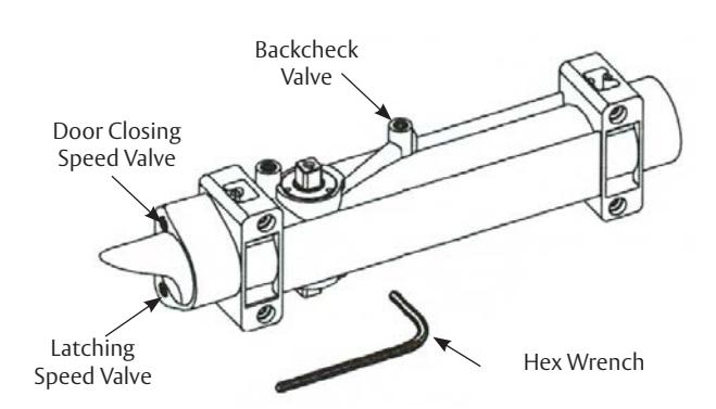
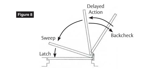
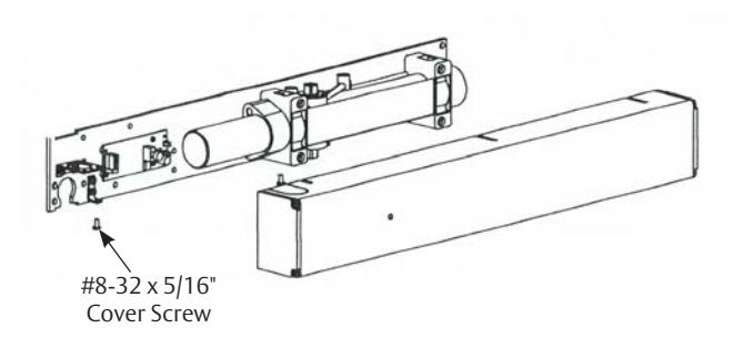
Figure 9
A7397C 09/21 1-800-727-5477 • www.sargentlock.com
2990 Hold-Open Double Lever Arm/Push (Stop) Side Mounting
Installation Instructions
4 Typical Wiring

CAUTION
- 1. Disconnect all power before beginning installation to prevent electrical shock and equipment damage.
- 2. Installer must be a trained, experienced service person.
- 3. All wiring must comply with applicable local electrical codes, ordinances and regulations.
- 4. Maximum wire size is 18AWG.
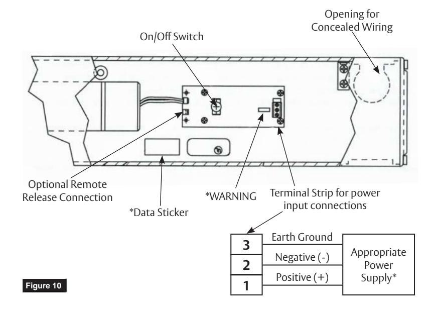
2990 Stand-Alone Units (Figure 10)
- 1. Wire stand alone unit to appropriate power supply and fire alarm.
- 2. Refer to data sticker for proper input voltage and current specifications.

*WARNING: Input power supply must match circuit board voltage rating, either 24VAC/DC or 120VAC. (Refer to data sticker)
- 3. Energize power supply.
- 4. Open door to hold-open point. Door should hold open.
- 5. Depress on/off switch. Door should close and latch.
- 6. Adjustment of spring power may be necessary to ensure proper latching. See Final Adjustment and Regulating Procedures section.
- 7. Depress on/off switch again. Open door to hold open position; door will hold open.
A7397C 09/21 1-800-727-5477 • www.sargentlock.com
2990 Hold-Open Double Lever Arm/Push (Stop) Side Mounting
Installation Instructions
5 Optional 80- Prefix Bypass Hold Open Switch for 2960, 2970 & 2990 FIREGUARD®
Switch Cam General Information The 80 prefix switch allows initial hold open point to be adjustable from 20 degrees through full door opening. This adjustment is done using a cam on spindle opposite from where arm mounts.
Figure 11
Adjustment Instructions

IMPORTANT
- 1. CAUTION: Disconnect all input power beginning installation to prevent electrical shock and equipment damage.
- 2. Installer must be a trained, experienced service person.
- 3. All wiring must comply with applicable local electrical codes, ordinances and regulations.
INSTALLATION
- 1. Mount closer/holder per instruction sheet provided.
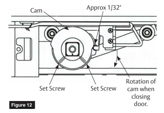
- 2. Locate switch roller and cam and loosen both set screws in cam. (Figure 11)
- 3. Open door to desired holding position and hold open with door stop. Rotate cam until switch roller is on lower section of cam and approximately 1/32" from bottom of incline. (Figure 12) Cam should be positioned so when door closes, roller on switch will ride up incline of cam operating the switch. Tighten on set screw in cam with hex key and pull door closed.
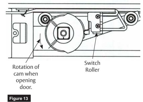
- 4. Pull door open to desired hold open position. When switch roller travels down to bottom of incline, door closer will function as a standard multi-point holder. (Figure 13) Depending on door size and closer fall back, cam may need to be adjusted so that switch roller is positioned further from base of incline. When cam is positioned properly for desired door operation, tighten both set screws firmly.
CAM IN DOOR OPEN POSITION
Set Screw (2 Places)
Roller
CAM IN DOOR CLOSED POSITION
A7397C 09/21 1-800-727-5477 • www.sargentlock.com
2990 Hold-Open Double Lever Arm/Push (Stop) Side Mounting
Installation Instructions
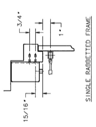
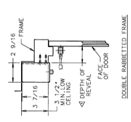
6 Template
| DIM 'A' | 11,1/8 | + | 11 15/16* | ||
| 10° 10 170° 11 1/8 | * * * | 10° TO 150° 11, 15/16° | 10. 10 170. | ||
| DOOR OPENING HOLD OPEN | 180* | - | 160 | 180 | - |
| DEPTH OF ARM ASSEMBLY MAXIMUM REVEAL FURNISHED DOOR OPENING |
2991, 9-2991
& 12-2991 0 TO 1 3/4 TYPE "0" ARM |
2992, 9-2992
& 12-2992 1 7/8 TO 4 TYPE "0Z" ARM |
TYPE "0ZA" ARM | 2994, 9-2994 4 1/8 TO 7 TYPE *0Y* ARM |
2995, 9-2995
& 12-2995 |
| 0. TO 1 3/4. | 1 7/8* TO 4* | 4 1/8* 10 7* | 4 1/8* T0 7* | 7 1/8* T0 8 5/8* | |
| MODEL No. |
2991, 9-2991
& 12-2991 |
2992, 9-2992
& 12-2992 |
2993, 9-2993
& 12-2993 |
2994, 9-2994
& 12-2994 |
2995, 9-2995
& 12-2995 |
| DESCRIPTION MODEL No. | ULTI-POINT 2991-29-2993 0 TO 1 3.74 TYPE -0 - ARM CLD-OPEN 2892-2993 1 7.78 TO 4 TYPE -0.2 - ARM CLD-OPEN 2893-2-9933 4 1.78 TO 7 TYPE -0.2 - ARM IREGUARD 2893-2993 4 1.78 TO 7 TYPE -0.2 - ARM IREGUARD 2893-2993 4 1.78 TO 7 TYPE -0.7 - ARM 295-295-392995 7 1.78 TO 8 5/8 TYPE -0.7 - ARM 295-295-295-3 7 1.78 TO 8 5/8 TYPE -0.7 - ARM | ||||

SARGENT Manufacturing Company 100 Sargent Drive New Haven, CT 06511 USA 800-727-5477 www.sargentlock.com
Founded in the early 1800s, SARGENT® is a market leader in locksets, cylinders, door closers, exit devices, electro-mechanical products and access control systems for new construction, renovation, and replacement applications. The company's customer base includes commercial construction, institutional, and industrial markets.