Installation Instructions for #855 Signal Switch Kit
Open the original PDF document
View PDFInstallation and Wiring Instructions
855 Signal Switch Kit
with ElectroLynx® Connector System
The 855 Signal Switch Kit is designed to be retrofit into an existing 80 Series rail assembly. The signal switch monitors the touch bar and signals a remote location that someone has egressed. The 855 signal switch can also be used as a request to exit switch, to de-energize a mortise lock.
A. Preliminary Preparation:
- 1. Provide a 1/4" diameter minimum raceway in the door to allow insertion of electrical wires running between signal switch and electric hinge.
- 2. Wiring instructions see wiring diagram for necessary information.
B. Installation Procedure:
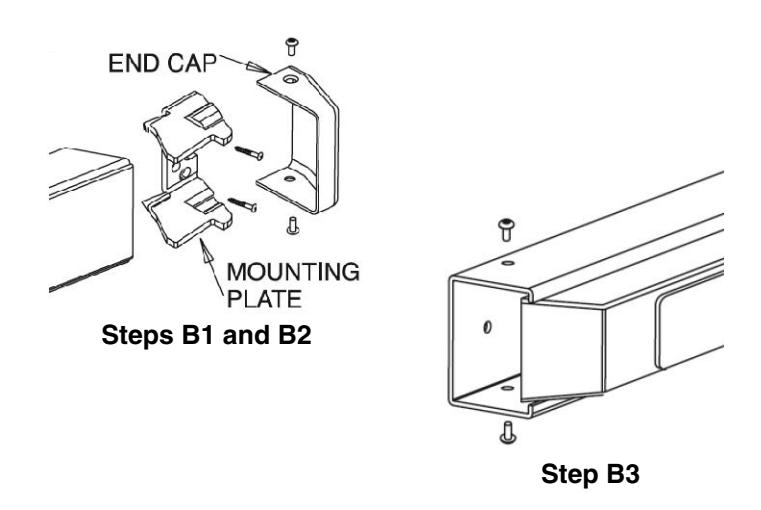
- 1. Remove end cap by taking out two (2) screws securing it.
- 2. Remove mounting plate by taking out two (2) screws securing it.
- 3. Remove two (2) #8-32 truss head screws holding rail to chassis.
- 4. Remove rail from door.
- 5. Slide mounting insert out of rail.
- 6. Loosen two (2) #6-32 flat head screws on back of rail (closer to hinge).
- 7. Lift connecting arm bracket and slip 855 switch assembly under bracket, as shown.
- 8. Install switch leaf under tail of connecting arm. Important: Switch leaf may break if installed on top.
- 9. Ensure connecting arm bracket is sitting flush against rail mount.
- 10.Tighten #6-32 screws.
- 11. Slide mounting insert back into rail.
- 12. Install rail onto chassis and tighten #8-32 truss head screws.
- 13. Reinstall mounting plate and end cap with appropriate screws.
C. Installation Notes:
- 1. Door without ElectroLynx connector system: Cut 8-pin connector off signal switch wires and hardware to electric hinge as required.
- 2. Wiring to pigtail harness or electric hinge is per facility wiring requirement.

This product can expose you to lead which is known to the state of California to cause cancer and birth defects or other reproductive harm. For more information go to www.P65warnings.ca.gov.
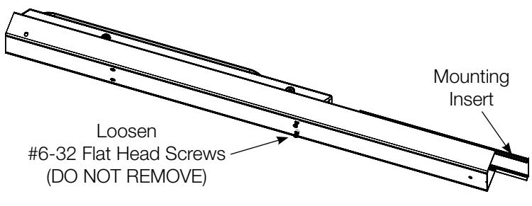
Steps B5 and B6
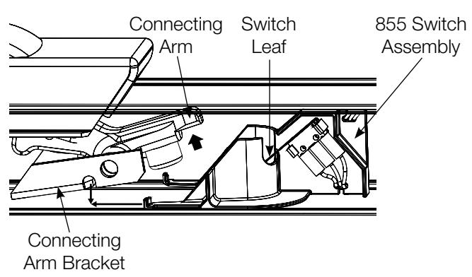
Steps B7 and B8

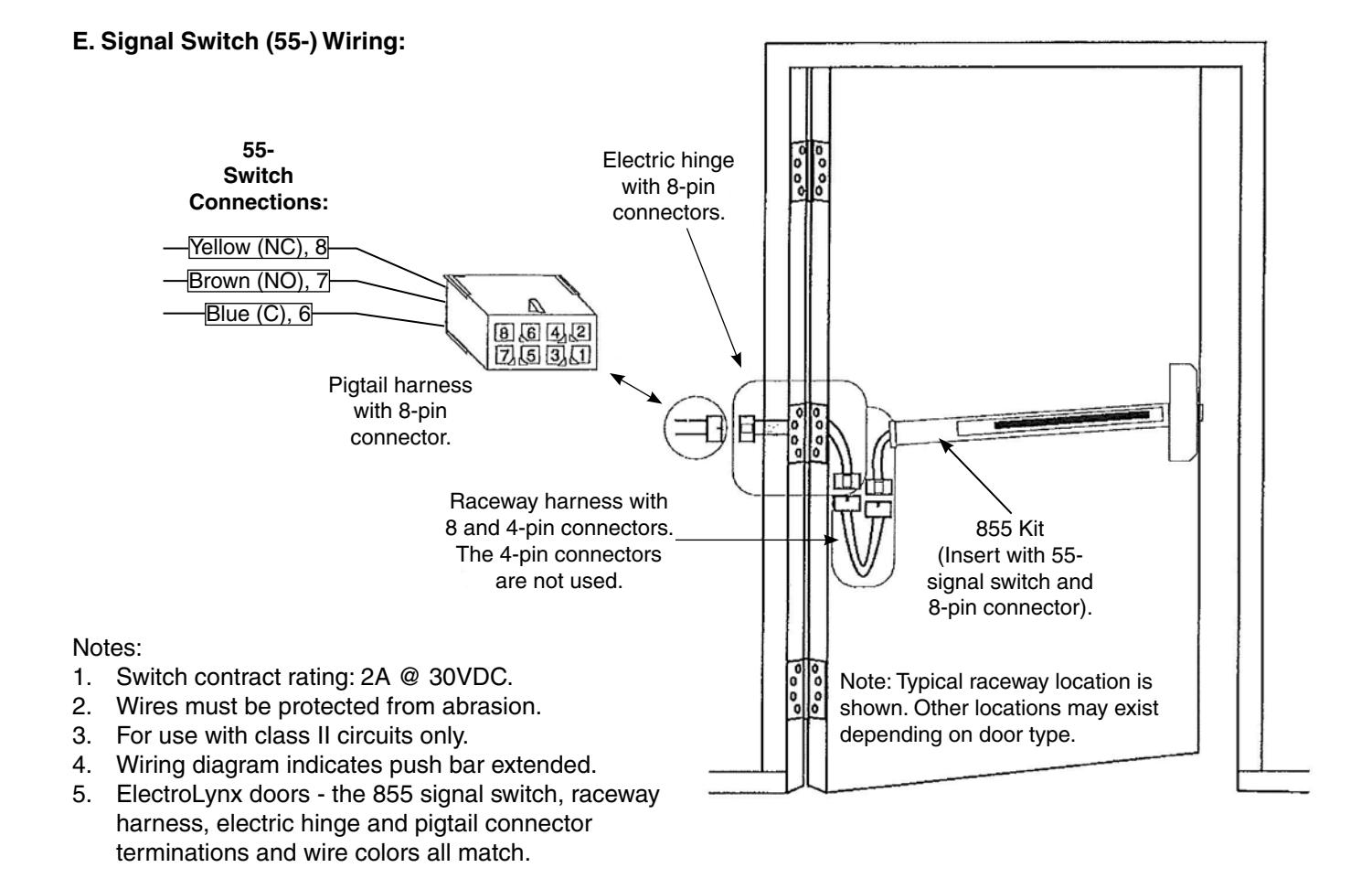
D. Door with ElectroLynx connector system:
The only wiring required is to the loose wires on the pigtail harness assembly on the frame side of the electric hinge.
IMPORTANT:
The plug and receptacle connectors are designed to mate and lock together as shown in the figure. Plug the connectors into each other with the locking mechanism aligned as indicated.
DO NOT FORCE CONNECTORS ON ANY OTHER WAY.
SARGENT Manufacturing Company 100 Sargent Drive New Haven, CT 06511 USA 800-727-5477 www.sargentlock.com