Installation Instructions for 7900 & 8200 Mortise Locks with Studio Collection Levers
Open the original PDF document
View PDFInstallation Instructions

7900 & 8200 Series Mortise Locks
with Studio Collection Levers
1 Tools Required
-
•
#2 and #3 Phillips screwdriver
•
Flat blade screwdriver
•
T20 Torx wrench
•
1/8" Allen wrench
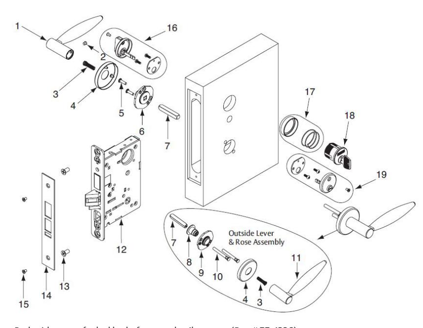
2 Package Contents
All trim components will vary by function number. For one sided trim, see reference document A7028.
| Fig. | Part # | Description | Qty | |
|---|---|---|---|---|
| 1 | — |
Inside lever (designs vary- some
handed) |
||
| 2 | 82-1623 | Lever set screw 1/4-28 (wide flat head) | ||
| 3 | 82-0347 | Lever spring | ||
| 4 |
696 x
Design |
Rose (designs vary) | ||
| 5 | 01-1495 | Machine screw #8-32 x 5/8" | ||
| 6 | Varies | Inside adapter & plate assembly | ||
| 7 | 82-1626 | Inside Studio spindle | ||
| 8 | 82-0691 | Bushing | ||
| 9 | Varies | Outside rose mounting plate | ||
| 10 | 81-0723 | Through-bolt posts | ||
| 11 | — |
Outside lever (designs vary-some
handed) |
||
| 12 | — | Lockbody (various functions) | ||
| 13 |
01-1019
01-2299 |
Machine screw #12 - 24 x 1/2" and
Wood screw #12 x 1-1/4" |
||
| 14 |
Varies x
Function |
Outside front plate | ||
| 15 | 01-1028 | Front screw #8 - 32 x 1/4" | ||
| 16 | 130KB | Thumbturn assembly (Varies x Design) | ||
| 17 | 1KB-1 | Cylinder collar/rosette (size varies) | ||
| 18 | — | Cylinder (various key systems) | ||
| 19 | — |
Emergency release assembly
Varies x Design 184 x Design |
||
Screw Pack with screws for lockbody, fronts and strike screws (Part # 77-4236)
Trim both side pack includes inside adapter plate assembly, spindle, through-bolt screws and set screw
- Rose Trim #79-2161
- Escutcheon Trim #82-4600
Trim one side pack includes inside adapter plate assembly, spindle, through-bolt screws, set screw and trim one side plate.
- Rose Trim #79-2162
- Escutcheon Trim #82-4599
WARNING
This product can expose you to lead which is known to the state of California to cause cancer and birth defects or other reproductive harm. For more information go to www.P65warnings.ca.gov.
A7896F 9/22
7900 & 8200 Series Mortise Locks
with Studio Collection Levers
Installation Instructions
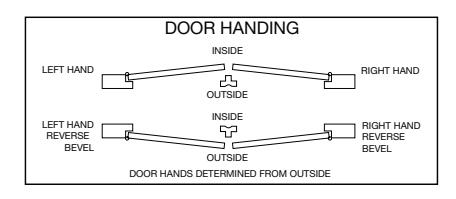
3 Door Preparation
- 1. Important: Check template A7057 to prep door for function holes, size & location. Verify strike location according to template. Clean out door pocket and door edge of any debris.
- 2. Make sure the handing of the lock (latch & locking piece) match the handing of the door. Slide lock into the door and hold.
- 3. Slide outside lever & rose assembly (or lever & escutcheon assembly) through the door; lock body and hold.
Note: Keep door open while installing lock. Note: If installing lever onto only one side of the door, see separate instruction sheet A7028.
4 Sectional Trim
• Assemble keyed cylinder first through narrow end of spring, and then through the wider opening of the collar (or escutcheon). Assemble onto door by threading into the lock until cylinder face is flush with collar edge. Pulling the key slightly out of cylinder will help to thread the cylinder in. For square collars, align pin to ensure collar is positioned correctly. See #4.
Note: SARGENT logo must be horizontal & on the top portion of the cylinder.
- Tighten cylinder clamp screw (#2 Phillips screwdriver). See #5.
- Secure lock in door with two wood screws (12 X 1-1/4" or machine screws 12-24 X 1/2"). Do NOT tighten completely at this time. See #6.
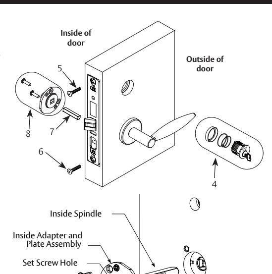
- Insert inside spindle into square hole of mortise lock, with spindle slot directed away from the mortise body and aligned with the set screw hole in the inside adapter. See #7a.
- Slide inside adapter and plate assembly over spindle, and secure with (2) 8-32 X 5/8" Phillips machine screws. See #8.
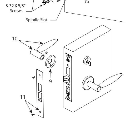
- Align posts in rose with holes in adapter & plate assembly, and press on until rose is tight against door face. See #9.
- Attach inside lever and secure with 1/8" Allen wrench. See #10.
- Assemble thumbturn/emergency release (if provided) according to instructions on bag.
- Check for proper lock operation by function prior to closing door.
- First tighten two lockbody screws completely, then attach outside front with two flat head screws 8-32 X 1/4". See #11.
Note: Removable Core or Interchangeable Core cylinders require a control key (key stamped with "C") to remove and install the inner cylinder core. This is not provided standard; must be requested separately. If requesting 1-Bitted control key, specify 113511 cut.

7900 & 8200 Series Mortise Locks
with Studio Collection Levers
Installation Instructions

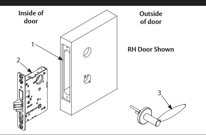
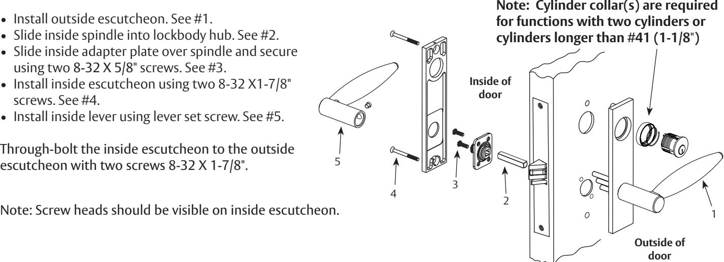
5 CE, LE1 and TE Escutcheon Trim
- Install outside escutcheon. See #1.
- Slide inside spindle into lockbody hub. See #2.
- Slide inside adapter plate over spindle and secure using two 8-32 X 5/8" screws. See #3.
- Install inside escutcheon using two 8-32 X1-7/8" screws. See #4.
- Install inside lever using lever set screw. See #5.
Through-bolt the inside escutcheon to the outside escutcheon with two screws 8-32 X 1-7/8".
Note: Removable Core or Interchangeable Core cylinders - require a control key (key stamped with "C") to remove and install the inner cylinder core. This is not provided standard; must be requested separately. If requesting 1-Bitted control key, specify 113511 cut.
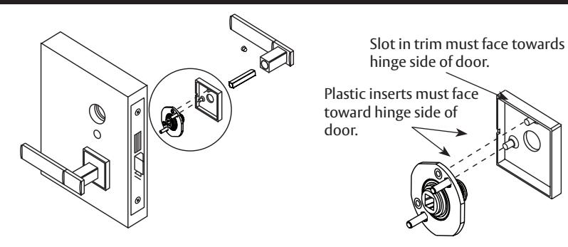
6 Installing E2, E3 and E4 Square Roses
The roses and their mounting plates need to be oriented correctly during installation. Failure to do so causes roses that are crooked on the door. The proper orientation for the plastic rose-mounting inserts points toward the hinge side of the door. The rose is oriented with the slot facing the hinge side of the door.
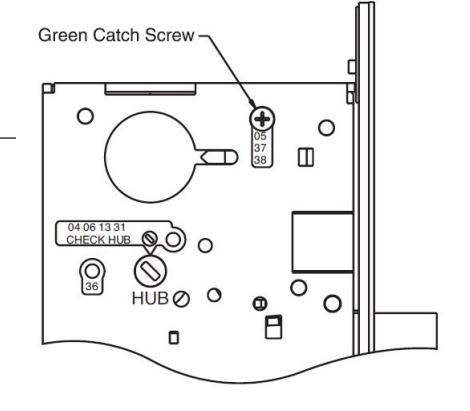
7 Multi-Function Lockbody
8200 Mortise Lock ONLY Multi-function Lockbody Options 04, 05, 06, 13, 31, 36, 37, 38
How to Change Function of Lock:
Green catch screw must be located as designated on lock case to create desired function.
- When moving green catch screw to 04, 06, 13 & 31 functions, hub position must be at 45° as shown on lockcase. See How to Change Hand of Lock, page 4.
- When moving green catch screw on 15 function, slot in hub must be in vertical orientation.

7 Multi-Function Lockbody, continued
Items needed to create each of the following functions:
|
Function Outside
Lever |
Inside
Lever |
Trim One
Side Kit |
Outside
Cylinder |
Inside
Cylinder |
Thumb
Turn |
|
|---|---|---|---|---|---|---|
| 04 | X | X | X | |||
| 05 | X | X | X | X*** | ||
| 06 | X | X | X | |||
| 13 | X | X | ||||
| 15 | X | X | ||||
| 31 | X | X | X | |||
| 36 | X | X | X | |||
| 37 | X | X | X | |||
| 38 | X | X | X | X |
- *** 130 KB thumb turn (designs vary) is used with rose trim only, escutcheon trims requiring thumb turns, must be preassembled at the factory
- #41 Cylinder is standard for both single & double cylinder functions for 1-3/4" thick door
NOTE: Trim one-side functions always require an inside trim assembly which can be used on the inside or outside of the door
| Type of Rose/Escutcheon | Kit Part Number | ||
|---|---|---|---|
| Trim one side kit | CO, CR, LN, O, TO & TR | 82-3208 | |
| Trim one side kit | CE, LE1 & TE Escutcheon | 82-3209 | |
8 8200 Only - How To Change Hand of Lock
( 7900 - see instruction label on lockbody )
Note: Red surface of locking piece must face secure (keyed/locked) side of door.
To rotate locking piece:
- 1. Position lockbody with red surface of locking piece visible
- 2. Insert blade type screwdriver into locking piece slot to rotate locking piece
- 3. Push locking piece toward back of lock body and rotate 180° until RED surface shows on opposite side
IMPORTANT: 04, 06, 13 and 31 Functions require:
- • Green catch screw to be removed
- • Rotate hub 45 degrees to vertical position
- • Rotate locking piece for required hand
- • Red surface faces locked side of door
- • Rotate hub to the original 45 degree position as shown on lockcase
- • Green catch screw is then reinstalled
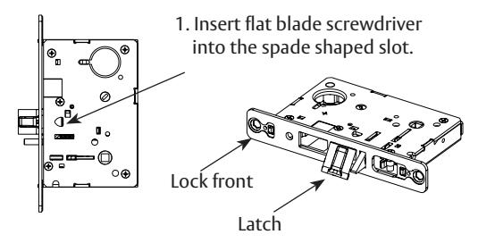
Note: Beveled surface of latch must face strike. The deadlatch is self adjusting. To change hand of latch (See step 1 in the figure to the right).
- 4. Rotate screwdriver 90º to push latch out until back of latch clears lock front.
- 5. Then rotate latch 180º. Latch will then re-enter lockbody.
Note: Latch can not be unscrewed.
SARGENT Manufacturing Company 100 Sargent Drive New Haven, CT 06511 USA 800-727-5477 www.sargentlock.com
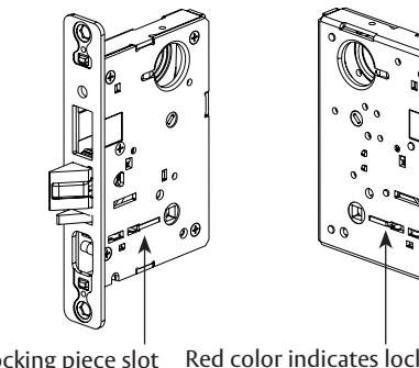
Locking piece slot Red color indicates locked side of door or hold black side (91 and 92 Functions)