Installation Instructions for 7 Line, 10 Line Lever Handles for Sargent Removable Core or Arrow,Best,Falcon Interchangeable Core
Open the original PDF document
View PDFINSTALLATION INSTRUCTIONS FOR
7 and 10 Line Levers with SARGENT Removable Core (63-) or Arrow, Best and Falcon Interchangeable Core

FOR INSTALLATION ASSISTANCE CALL SARGENT AT 1-800-727-5477 • www.sargentlock.com
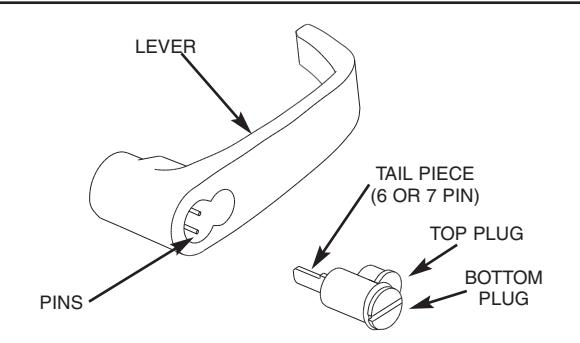
REMOVING DISPOSABLE PLASTIC PLUGS
- 1. Rotate bottom plug until notch lines up with indicator dot on top plug.
- 2. Pull bottom plug straight out, then remove top plug.
Important- Save tail piece on back of construction plug to be reused with cylinder.

INSERT DISPOSABLE PLASTIC PLUGS
NOTE: Tail piece or pins version construction can be used depending on lock. See reverse side for description.
-
1.
Insert top plug into top hole in lever.
- If pins version insert bottom plug with notch facing horizontal on to pins.
- If tail piece version insert the tail piece into the bottom plug then insert bottom plug with notch facing horizontal into lever.
15°
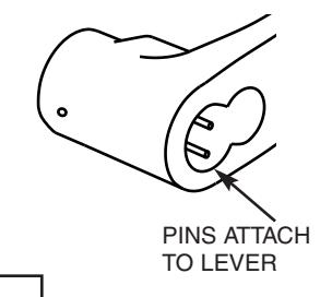
1B PINS VERSION
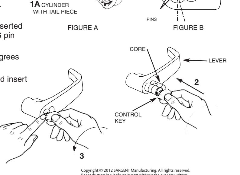
REMOVING CYLINDER CORE
- 1. Insert control key
- 2. Turn clockwise until stop is reached
- 3. With key in this position–pull out core
- 4. To remove key –return to horizontal position and withdraw
NOTE: If a control key is needed for one bitted removable core (63-) cylinders, cut a key blank from bow to tip using 113511.

INSERTING CYLINDER CORE
NOTE: Tail piece or pins version construction can be used depending on lock. See reverse side for description.
-
1. A) Tail piece version
The tail piece should be inserted into back of cylinder. (Use tail piece stamped "6" if 6 pin cylinder and "7" if 7 pin cylinder.) See figure A
- B) Pins version Rotate the pins gently to 15 degrees offset. See figure B.
- 2. Then insert control key into replacement core and insert cylinder into lever
- 3. To remove key –return to horizontal position and withdraw

For easier removal hold core in place while starting to withdraw key.
Reproduction in whole or in part without the express written permission of SARGENT Manufacturing is prohibited.

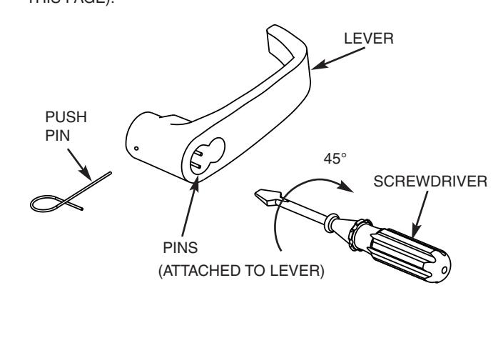
- 1. REMOVE CYLINDER (REFER TO BACK SIDE OF THIS PAGE).
- 2. INSERT FLAT-BLADE SCREWDRIVER INTO LEVER BETWEEN PINS.
- 3. GENTLY TURN SCREWDRIVER 45 DEGREES CLOCKWISE.
- 4. AT THE SAME TIME, INSERT PUSH-PIN INTO HOLE ON LEVER IN ORDER TO DEPRESS LEVER CATCH.
- 5. PULL THE LEVER FROM THE TUBE.
INSTALLING LEVER
- 1. PUSH LEVER ONTO TUBE AS FAR AS IT WILL GO.
- 2. INSERT FLAT-BLADE SCREWDRIVER INTO LEVER BETWEEN PINS.
- 3. GENTLY TURN SCREWDRIVER 45 DEGREES CLOCKWISE.
- 4. PUSH LEVER AGAIN TO MAKE CERTAIN LEVER CATCH ON TUBE IS ENGAGED IN LEVER BY PULLING ON THE LEVER.
- 5. INSERT CYLINDER (REFER TO BACK SIDE OF THIS PAGE).
PINS VERSION TAILPIECE VERSION
REMOVING LEVER HANDLE REMOVING LEVER HANDLE
- 1. REMOVE CYLINDER (REFER TO BACK SIDE OF THIS PAGE).
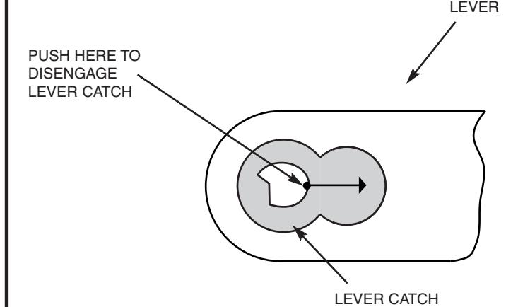
- 2. INSERT PUSH PIN OR SCREW DRIVER INTO FIGURE EIGHT OPENING IN LEVER HANDLE. PUSH LEVER CATCH IN DIRECTION SHOWN TO DISENGAGE IT FROM THE LEVER.
- 3. SLIDE THE LEVER FROM THE TUBE.

TO BE INSERTED IN CYLINDER (6 PIN TAILPIECE SHOWN)
INSTALLING LEVER
- 1. PUSH LEVER ONTO TUBE UNTIL IT ENGAGES THE LEVER CATCH. MAKE SURE LEVER CATCH IS FULLY ENGAGED BY PULLING ON LEVER.
- 2. INSERT CYLINDER WITH TAIL PIECE. (REFER TO BACK SIDE OF THIS PAGE).