Installation Instructions for 4370 Series Cylinder Key Switches
Open the original PDF document
View PDFInstructions for the Installation of 4370 Key Switches

Switch Data
|
Model
New |
Model
Old |
Qty. | Contact | Туре |
Rear
View (ref) |
|---|---|---|---|---|---|
| 4370 | 4285 | 1 | SPDT | Maintained | Α |
| 4371 | N/A | 1 | SPDT | Momentary | Α |
| 4371L | 4282 | 1 | SPDT | Momentary w/LED's | A |
| 4371LT | 4284/ | 1 | SPDT | Time Delay | |
| | | | 4287 | Adj. 5-120 s. | С | ||
| 4372 | N/A | 1 | DPDT | Maintained | А |
| 4373 | N/A | 1 | DPDT | Momentary | Α |
| 4374 | N/A | 2 | SPDT | Maintained | В |
| 4375 | 4281 | 2 | SPDT | Momentary | В |
| 4375LH | 4286 | 2 | SPDT | Momentary | |
| _ | w/horn & LED's | D | |||
| 4376 | N/A | 2 | DPDT | Maintained | В |
| 4377 | N/A | 2 | DPDT | Momentary | В |
| 4378 | N/A | 1 | SPDT | Momentary/ | |
| 1 | SPDT | Maintained | В | ||
| 4378LH | 4283 | 1 | SPDT | Momentary/ | |
| 1 | SPDT | Maintained | |||
| w/horn & LED's | D | ||||
| 4379 | N/A | 1 | DPDT | Momentary/ | |
| 1 | DPDT | Maintained | В |
Suffixes:
L = LED's - one red, one green
H = Horn (Requires Double Gang)
T = Time Delay (Requires Double Gang)
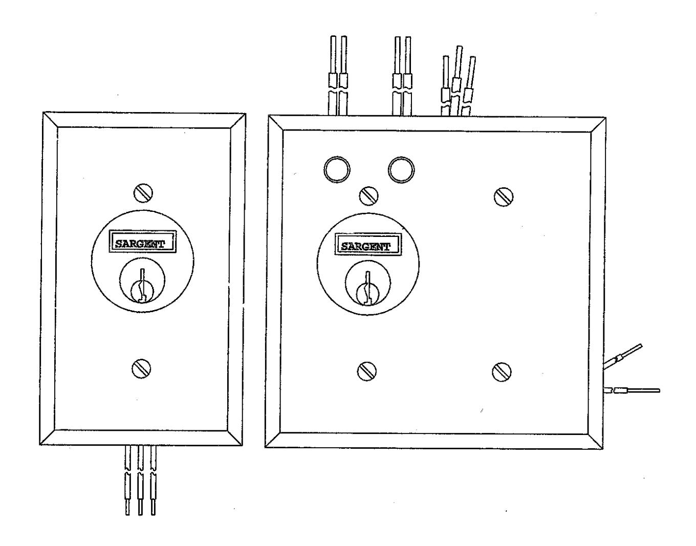
Rear View of Switch Assembly 1-GANG A 1-GANG C 2-GANG D
Faceplate & Outlet Box Dimensions
| Face Plate | Outlet Box Size | Appleton | RACO | ||||
|---|---|---|---|---|---|---|---|
| Height | Width | Height | Width | Depth | Cat No. | Cat No. | |
| 1-Gang | 4½" | 2¾" | 4" | 21/3" | 1%" | 4CS | 670 |
| 2-Gang (single switch) | 4%" | 4½" | 4" | 4" | 2½" | 132 | 680 |
| 2-Gang (double switch) | 4½" | 4½" | 411/46" | 411/16" | 2%" | ||

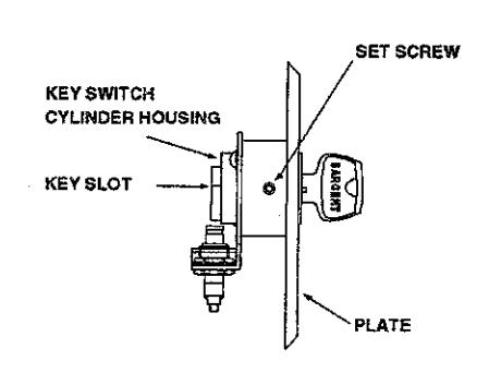
Cylinder Assembly & Switch Adjustment
Cylinder requires clover leaf cam (13-0921) packed standard with key switch
Cylinder Assembly
- · Thread key cylinder fully into key switch assembly stopping when the key slot is vertical
- · Secure into position with set screws located on either side of the assembly
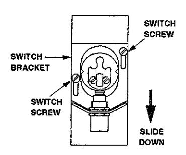
Switch Adjustment
- Loosen both screws holding the switch bracket in place and slide the bracket downward away from the key cylinder (as shown)
- · Grasp the key and rotate the cam so that the short lobe is directly above the switch
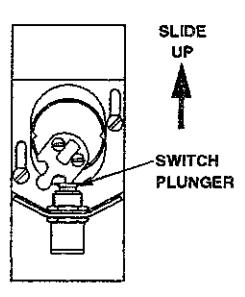
- Push up on the switch bracket until the switch plunger nearly bottoms within the switch
- Retighten the switch bracket holding screws
Final Check of Switch Operation
- · Rotate the key and observe that the small cam lobe depresses the switch plunger and the center cam lobe acts as a stop when it contacts the switch case
- · Minor readjustment may be necessary to obtain a smooth motion
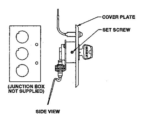
Installation of Key Switch into Outlet Box
- Connect switch and LED wires to wires in junction box
- Carefully insert key switch cylinder housing into junction box making sure switch wires clear junction box edges
- Fasten key switch cylinder housing to junction box with flat head screws provided
- Guide LED wires (if present) into top of junction box above key switch cylinder housing
- · Mount cover plate using slotted or spanner head screws provided and tighten

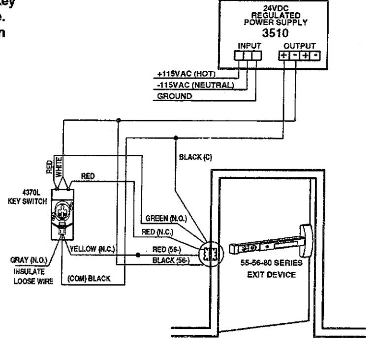
Typical Wiring & Operation for 4370L Key Switch
This application requires a SPDT maintained key switch to activate a latch retraction exit device. A key switch with LED's provides an indication when the device is energized.
Operation of 4370L Key Switch
- 1. Insert key into cylinder.
- 2. Rotate key to energize exit device - remove key.
- 3. Rotate key to de-energize exit device - remove key.

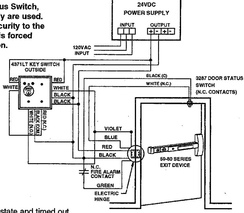
Typical Wiring & Operation for a 4371LT Key Switch
This application requires a SPDT momentary contact key switch with time delay to activate/deactivate a delayed egress system from a remote location. A 59-80 Series Exit Device, 3287 Door Status Switch. 4371LT Key Switch, and 3510 Power Supply are used. The door status switch provides added security to the opening by initiating the alarm if the door is forced open while the unit is in an armed condition.
Operation of 4371LT Key Switch
- Insert key into cylinder.
- 2. Rotate key to energize exit device - remove key.
- 3. Rotate key to de-energize exit device - remove key.
3510
NOTE: Wiring shown with timer in energized state and timed out.