Installation Instructions for 351 EHT Electromechanical Closer-Holder Device (Pull-Push Side)
Open the original PDF document
View PDFINSTALLATION INSTRUCTIONS 351 EHT Electromechanical Closer-Holder Device – Pull Side
CAUTION: FAILURE TO INSTALL OR ADJUST PROPERLY MAY RESULT IN INJURY OR DAMAGE. FOR ASSISTANCE CONTACT SARGENT AT 800-810-WIRE (9473) or www.sargentlock.com
NOTE: AN AUXILIARY DOOR STOP IS REQUIRED AT HOLD OPEN
CAUTION: !
- 1. DISCONNECT ALL POWER BEFORE INSTALLATION
- 2. ALL WIRING TO BE PERFORMED BY QUALIFIED PERSONNEL TO COMPLY WITH ALL APPLICABLE LOCAL CODES.
- 3. MAXIMUM WIRE SIZE IS 18 AWG.
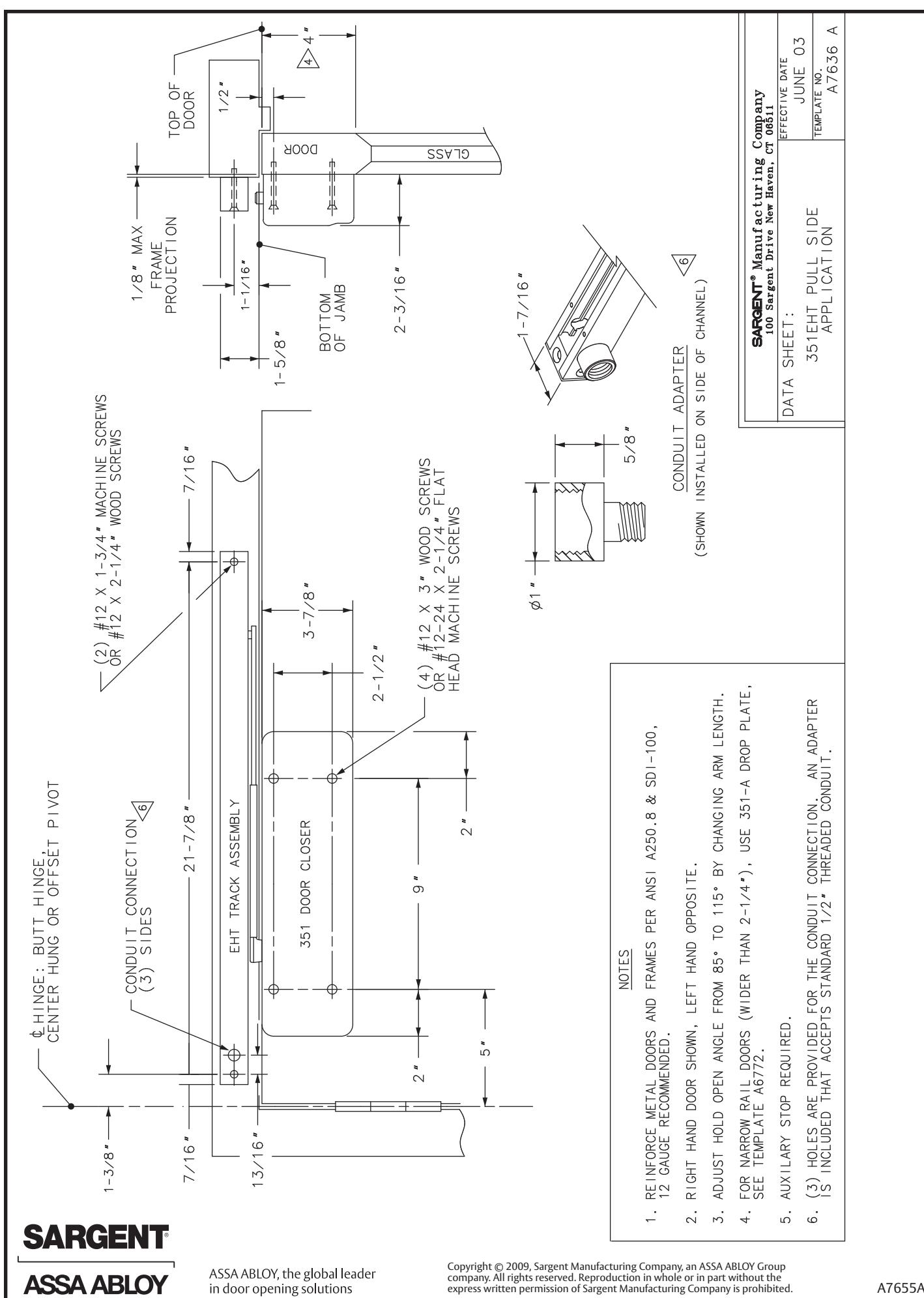
- 1 Use template from page 3; drill and tap door and frame for 12-24 machine screws, and prepare hole for conduit. Do not drill through channel, as damage will occur voiding warranty.
- 2 Install closer body to door with spring power nut away from hinge.

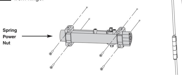
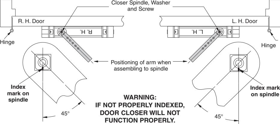
351 closers are non-handed, RH must be on top for right hand doors and LH must be on top for left hand doors.
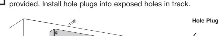
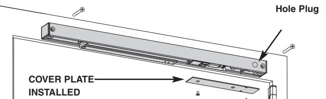
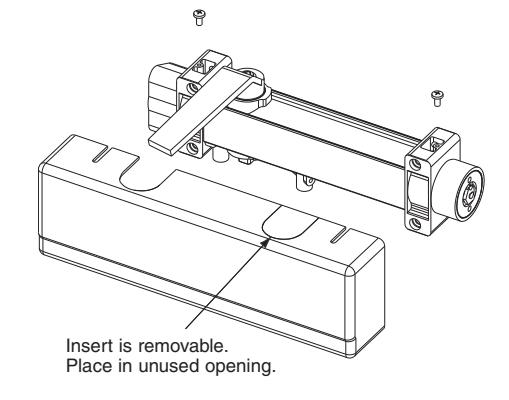
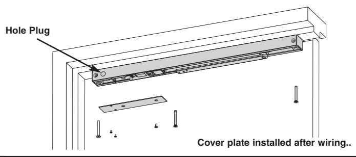
4 Secure track to frame with electronics toward hinge with screws provided. Install hole plugs into exposed holes in track.

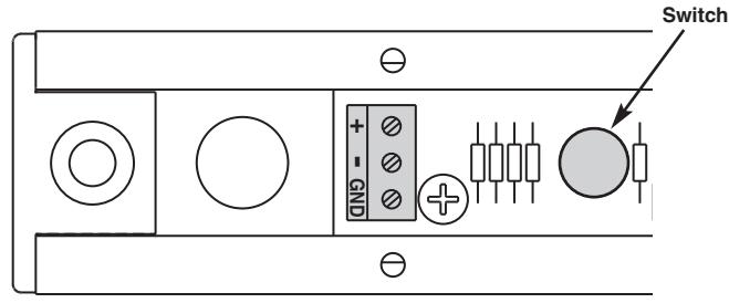
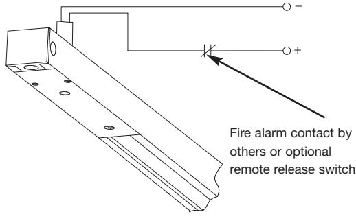
5 Connect 24VDC/VAC to terminal block marked "+", "-" and "GND" (if applicable). (NOTE: GND used if AC is used). On/Off
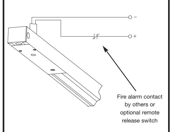
6 Wire through fire alarm contact OR Optional "Remote Release" switch is used.
AFTER WIRING
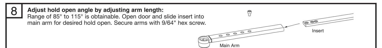
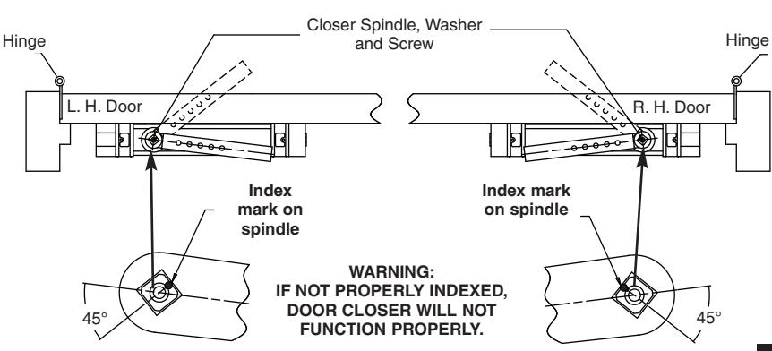
7 Use screw and washer to secure main arm to spindle with index mark as shown.
Copyright © 2009, Sargent Manufacturing Company, an ASSA ABLOY Group company. All rights reserved. Reproduction in whole or in part without the express written permission of Sargent Manufacturing Company is prohibited.
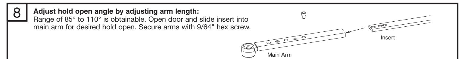
Final Adjustment and Regulating Procedures
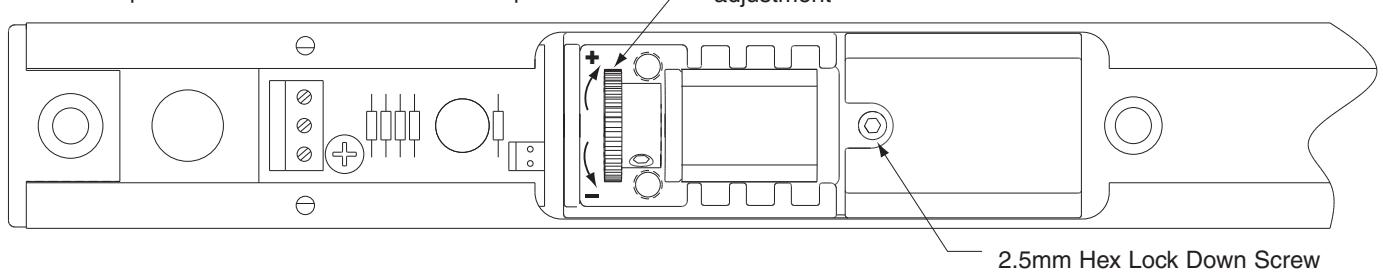
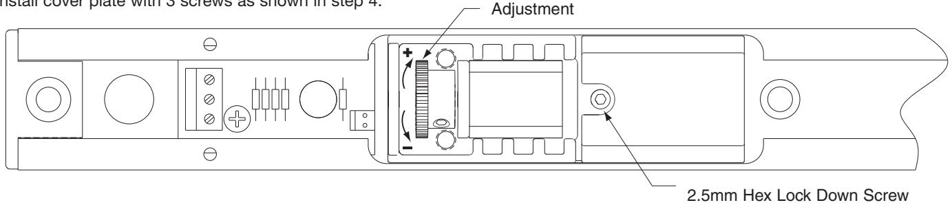
To adjust holding tension:
- Loosen 2.5mm lock down screw
- Turn knob for desired tension
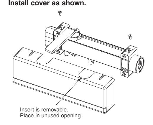
• Retighten 2.5mm lock down screw • Install cover plate with 3 screws as shown in step 4.
Holding tension adjustment
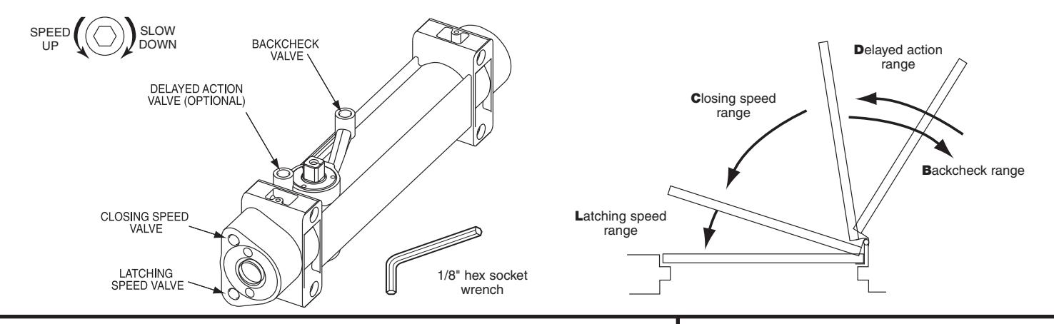
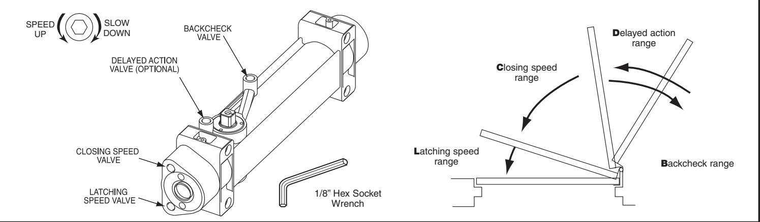
Closing and latching speeds:
Turn valves clockwise to slow down or counterclockwise to speed up door movement.
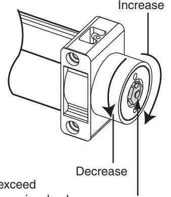
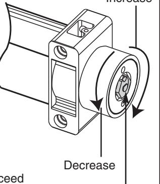
Backcheck:
Turn valve clockwise to increase or counterclockwise to decrease.
CAUTION: SET VALVE FOR SLIGHT CUSHIONING EFFECT; CLOSER CAN BE DAMAGED IF THE CHECKING ACTION IS TOO ABRUPT. NEVER USE THE BACKCHECK AS A DOOR STOP. ALWAYS USE A DOOR STOP TO STOP THE DOOR.
Delayed action feature (optional feature):
When provided, turn valve clockwise to slow down or counterclockwise to speed up door movement.
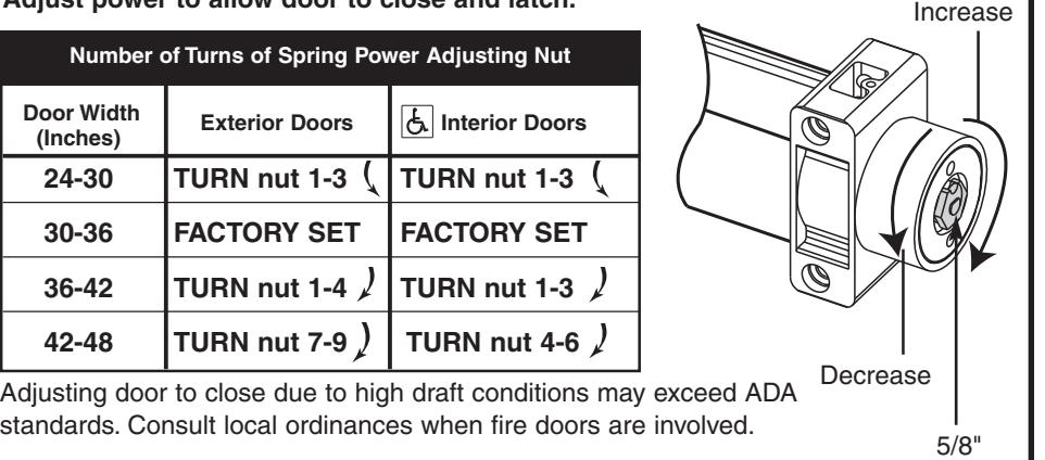
Adjust power to allow door to close and latch.
| Number of Turns of Spring Power Adjusting Nut | ||
|---|---|---|
|
Door Width
(Inches) |
Exterior Doors | Interior Doors |
| 24-30 | TURN nut 1-3 | TURN nut 1-3 |
| 30-36 | FACTORY SET | FACTORY SET |
| 36-42 | TURN nut 1-4 | TURN nut 1-3 |
| 42-48 | TURN nut 7-9 | TURN nut 4-6 |
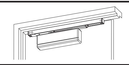
Install cover as shown.

Copyright © 2009, Sargent Manufacturing Company, an ASSA ABLOY Group company. All rights reserved. Reproduction in whole or in part without the express written permission of Sargent Manufacturing Company is prohibited. A7655A
Adjusting Nut
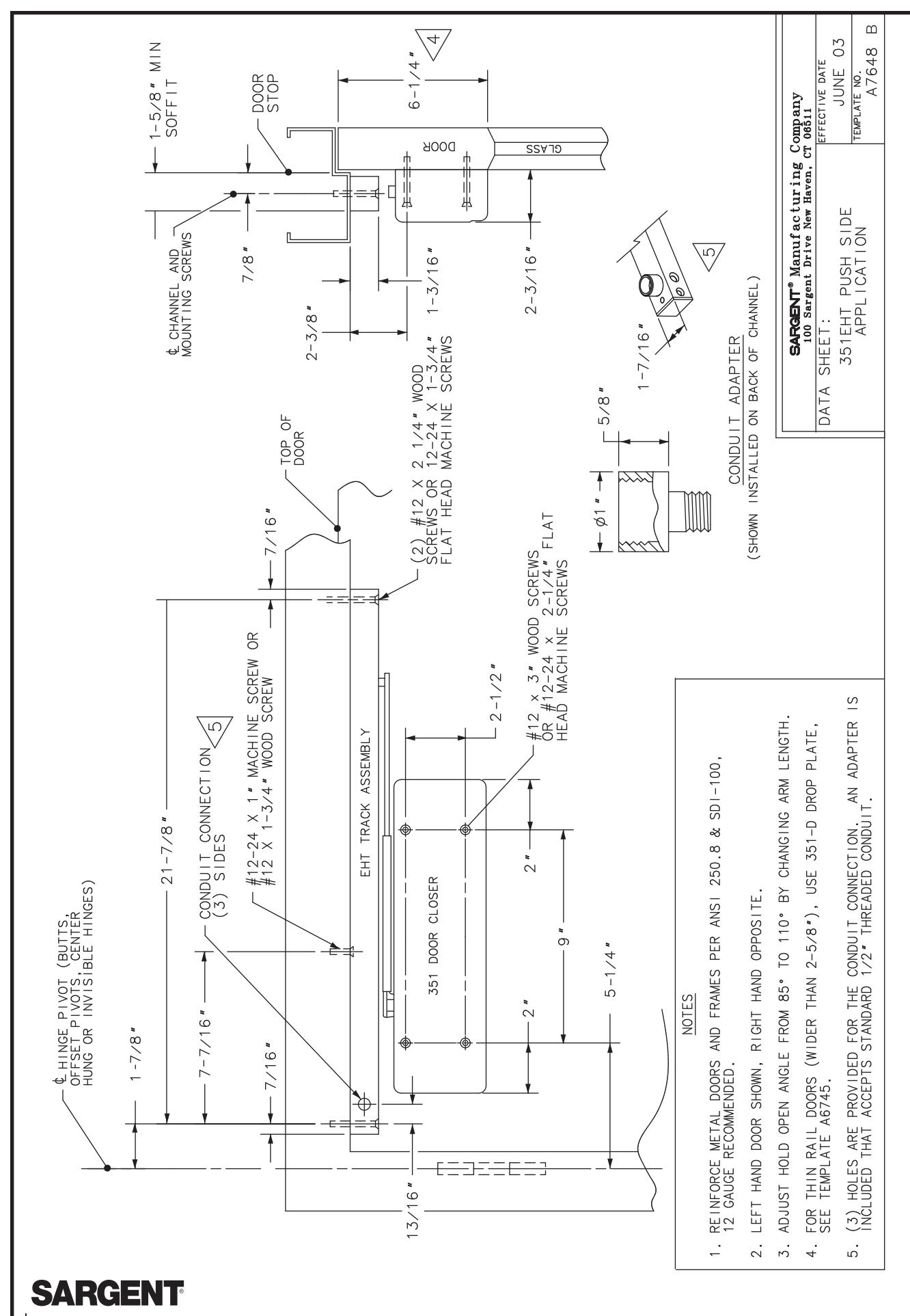
INSTALLATION INSTRUCTIONS 351 EHT Electromechanical Closer-Holder Device – Push Side
SARGENT
ASSA ABLOY
CAUTION: FAILURE TO INSTALL OR ADJUST PROPERLY MAY RESULT IN INJURY OR DAMAGE. FOR ASSISTANCE CONTACT SARGENT AT 800-810-WIRE (9473) or www.sargentlock.com
NOTE: AN AUXILIARY DOOR STOP IS REQUIRED AT HOLD OPEN
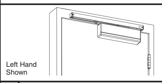
Left Hand
Shown
A CAUTION:
- 1. DISCONNECT ALL POWER BEFORE INSTALLATION
- 2. ALL WIRING TO BE PERFORMED BY QUALIFIED PERSONNEL TO COMPLY WITH ALL APPLICABLE LOCAL CODES.
- 3. MAXIMUM WIRE SIZE IS 18 AWG.
- Use template from page 6 and drill and tap door and frame for 12-24 machine screws. Prepare hole for conduit. Do not drill through channel, as damage will occur voiding warranty.
- 2 Install closer body to door with spring power nut away from hinge.
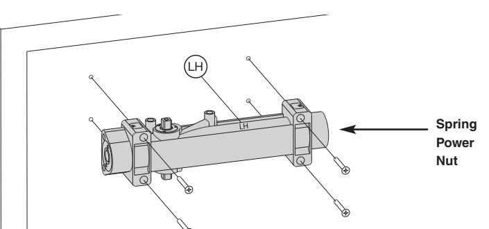
351 closers are non-handed, RH must be on top for right hand doors, and LH must be on top for left hand doors.
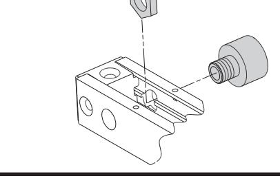
Attach conduit adapter to track with nut provided. Secure cable or conduit (by others) per local codes.
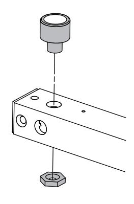
Secure track to frame with electronics toward hinge with screws provided. Install hole plugs into exposed holes in track.
Connect 24VDC/VAC to terminal block marked "+", "-" AND "GND" (if applicable). (NOTE: GND used if AC is used.) On/Off Switch
Wire through fire alarm contact OR optional "Remote Release" switch if used.
ASSA ABLOY, the global leader in door opening solutions
Rotate bottom spindle 45° with wrench. Use screw and washer to secure main arm to top spindle with index mark as shown.
Final Adjustment and Regulating Procedures
Holding Tension
To adjust holding tension:
- Loosen 2.5mm lock down screw
- Turn knob for desired tension
- Retighten 2.5mm lock down screw • Install cover plate with 3 screws as shown in step 4.
Closing and latching speeds:
Turn valves clockwise to slow down or counterclockwise to speed up door movement.
Backcheck:
Turn valve clockwise to increase or counterclockwise to decrease.
CAUTION: SET VALVE FOR SLIGHT CUSHIONING EFFECT; CLOSER CAN BE DAMAGED IF THE CHECKING ACTION IS TOO ABRUPT. NEVER USE THE BACKCHECK AS A DOOR STOP. ALWAYS USE A DOOR STOP TO STOP THE DOOR.
Delayed action feature (optional feature):
When provided, turn valve clockwise to slow down or counterclockwise to speed up door movement.
Door Width Exterior Doors Interior Doors (Inches) 24-30 TURN nut 1-3 TURN nut 1-3 30-36 FACTORY SET FACTORY SET 36-42 TURN nut 1-4 TURN nut 1-3 42-48 TURN nut 7-9 TURN nut 4-6 Adjust power to allow door to close and latch. Number of Turns of Spring Power Adjusting Nut
Adjusting door to close due to high draft conditions may exceed ADA standards. Consult local ordinances when fire doors are involved.

5/8"
Adjusting Nut
ASSA ABLOY