Installation Instructions for 1331 Door Closer with Arm Sets (JO, JOZ, and JP9)
Open the original PDF document
View PDFSARGENT® 1331 DOOR CLOSER INSTALLATION INSTRUCTIONS WITH FOLLOWING ARM SETS: JO, JOZ and JP9
Strength Adjustment From Size 1 Through 6.
CAUTION: FAILURE TO INSTALL OR ADJUST PROPERLY MAY RESULT IN INJURY OR DAMAGE
FOR ASSISTANCE, CALL SARGENT AT 1-800-727-5477 or www.Sargentlock.com
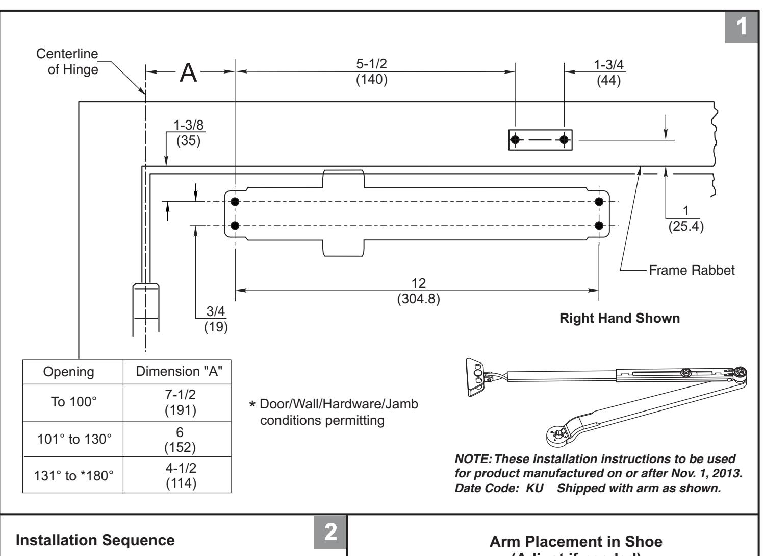
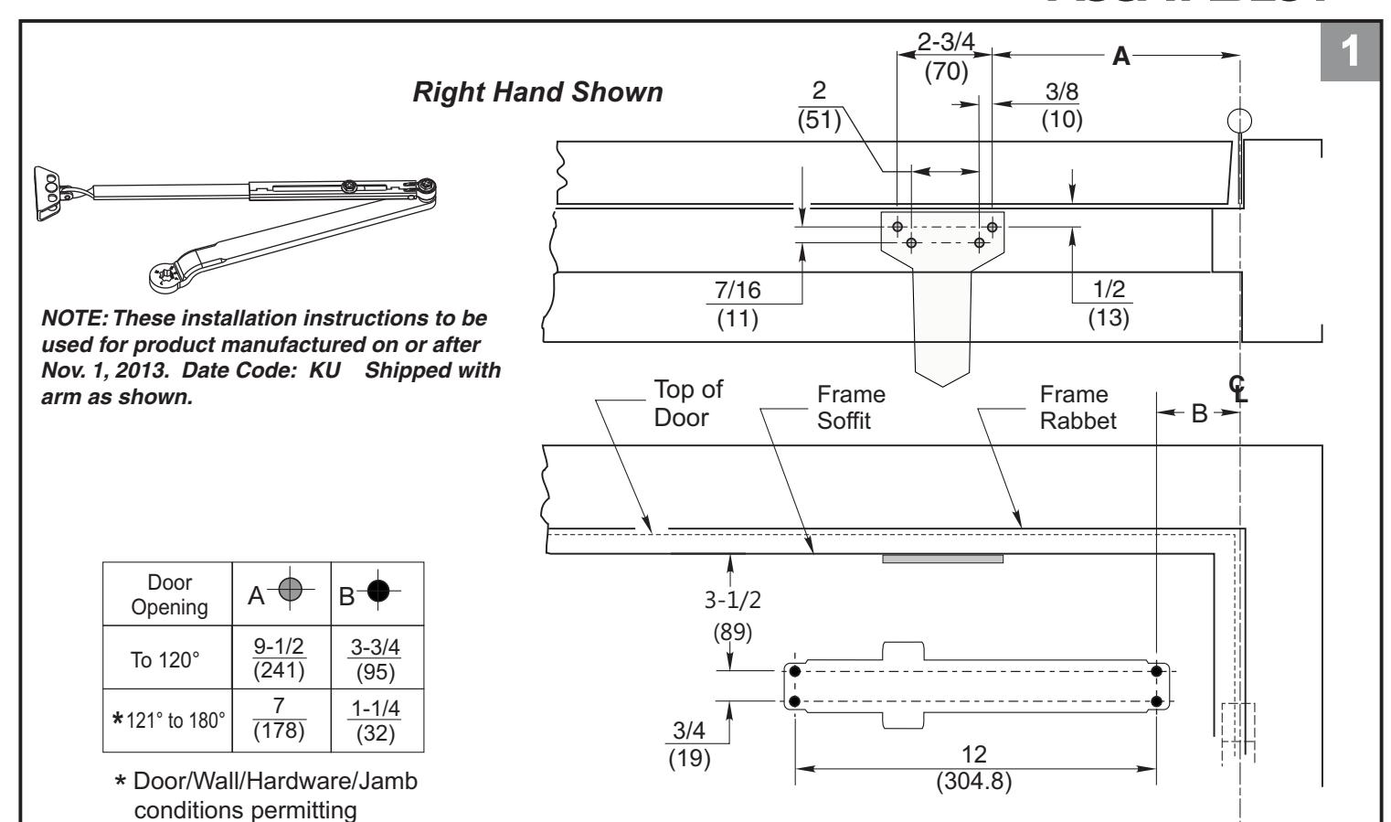
NOTE:These installation instructions to be used for product manufactured on or after Nov. 1, 2013. Date Code: KU and shipped with arms shown on template pages. See page 6 for date code location.
Choose From 1 of 3 Applications
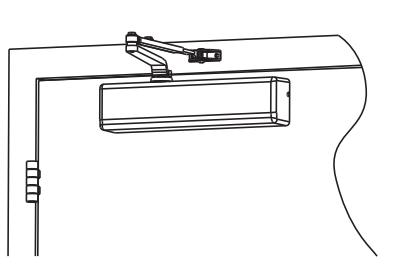
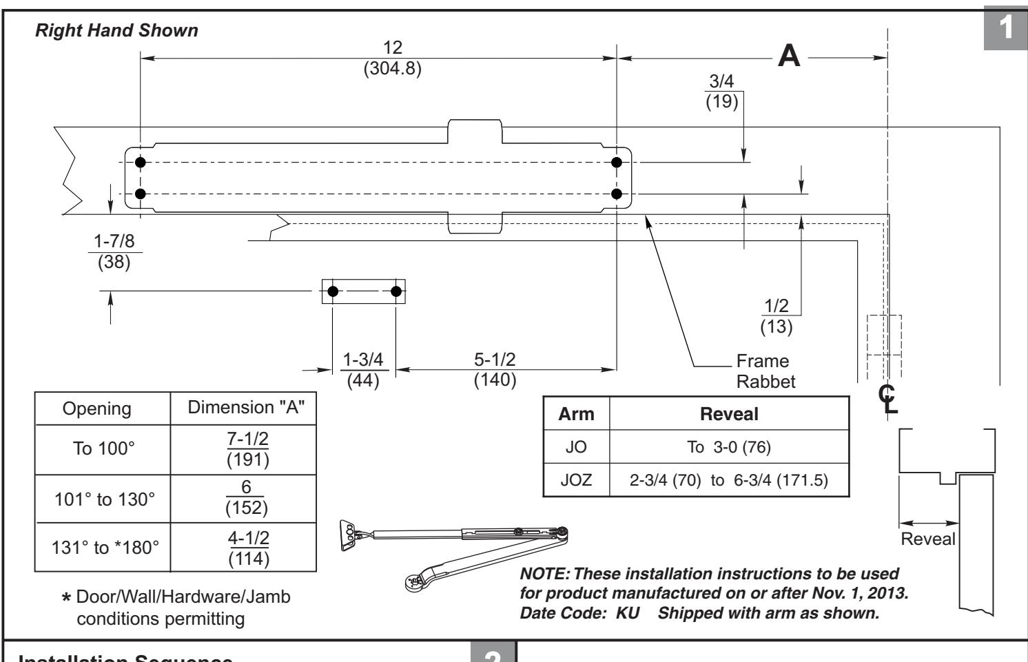
JO Arm (Regular Arm) Right hand (RH) door shown. Left hand reverse (LHR) See page 2
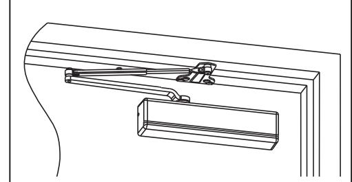
JP9 Arm (Regular Arm) Right hand (RH) door shown. Left hand reverse (LHR) See page 3
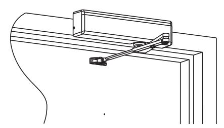
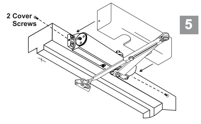
JO Arm (Top Jamb Arm) Right hand (RH) door shown. Left hand reverse (LHR) See page 5
- · Doors should be hung on ball bearing or anti-friction hinges.
- · A separate door stop is recommended.
- · Door and frame must be properly reinforced.
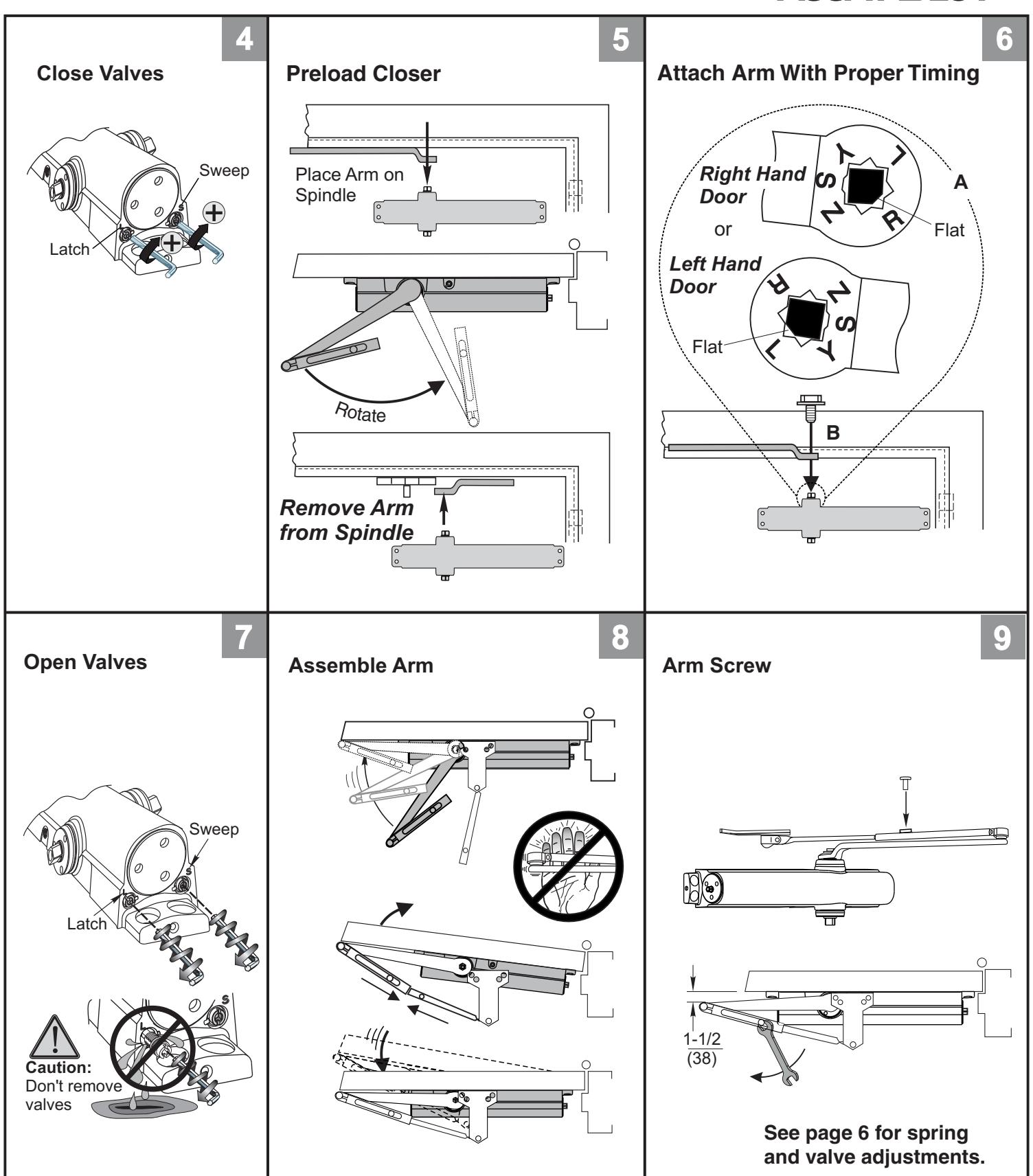
- · Always adjust spring power before adjusting control.
- · Adjust closing time speed between 3 and 7 seconds from 90° to 0°. Greater closing times may be required ADA.
- · These door closers should NOT be installed on the exposed side (weather side) of exterior doors
- · NOTE: For special applications a separate door and frame preparation template is packed with these instructions. Use this instruction sheet for installation sequence and closer adjustments only.
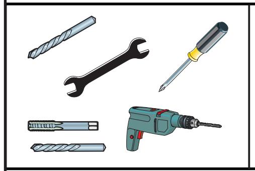
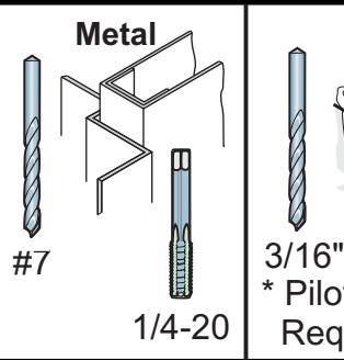
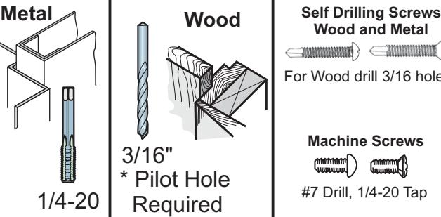
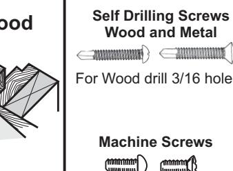
Machine Screws #7 Drill, 1/4-20 Tap

Drill 9/32 thru from Closer Side 3/8 Drill other side
Thru Bolt and Grommet Nut

Drill 3/8 Drill other Side 9/32 thru from Closer Side
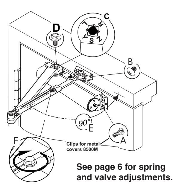
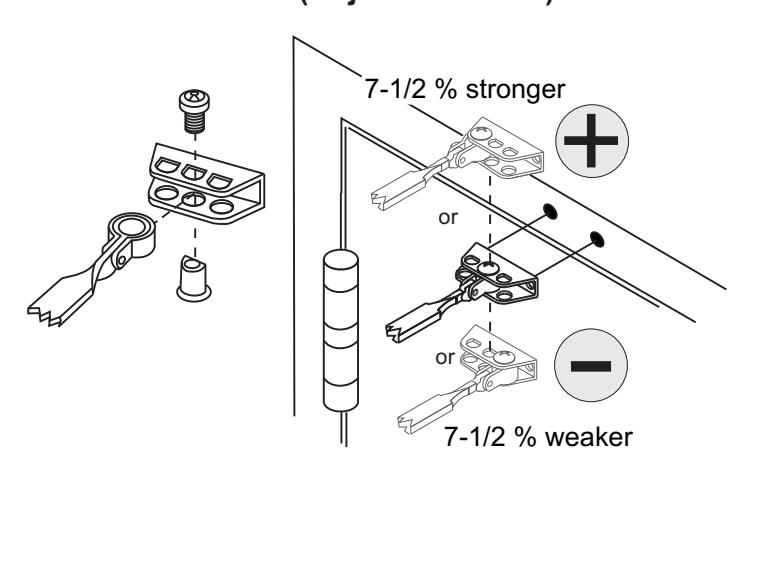
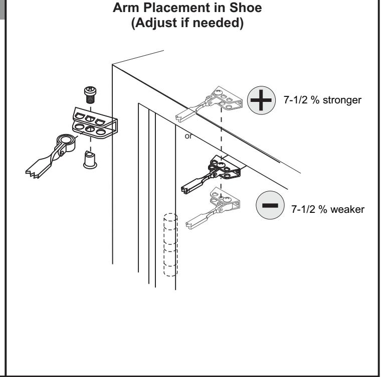
(Adjust if needed)
SARGENT
ASSA ABLOY
SARGENT
ASSA ABLOY
SARGENT
ASSA ABLOY
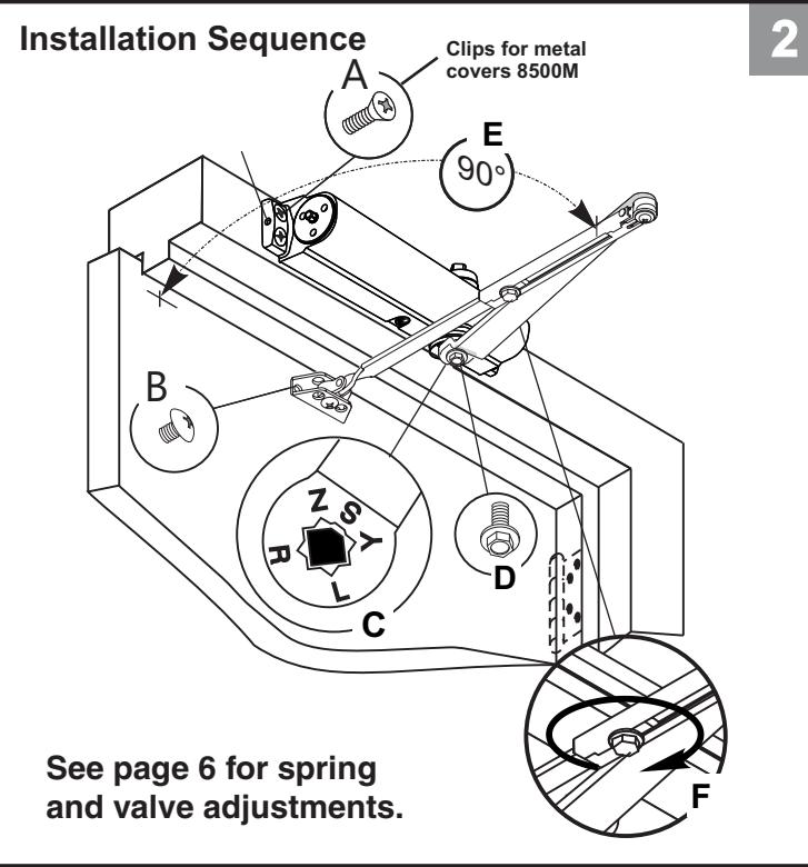
Spring Power Adjust
| Adjustment Chart | Number of Turns Required | |||||||
|---|---|---|---|---|---|---|---|---|
| Π| TYPE | MAXIMUM DOOR SIZE | - | |||||
| DOOR |
OF
INST. |
* |
32"
(0.85M) |
36"
(0.90M) |
42"
(1.00M) |
48"
(1.20M) |
||
| 8100/8300/8500 | INTERIOR |
Regular Arm
Top Jamb |
TURNS OF
OWER NT WRENC |
5 | 8 | 11 | 13 | |
| Parallel Arm | 7 | 10 | 13 | 16 | ||||
| EXTERIOR |
Regular Arm
Top Jamb |
7 | 10 | 13 | 16 | |||
| Parallel Arm | 9 | 12 | 15 | 18 | ||||
*20 FULL (360°) TURNS MAXIMUM AVAILABLE Closer is shipped set at mid range setting = 10 turns

The closing force is adjustable from a size 1 to a size 6, as outlined in ANSI Standard A156.4. When these series of door closers are installed and adjusted to conform to ADA reduced opening force requirements (5 lbs max.) for interior doors, they may not have adequate closing force to reliably close and latch the door. Power adjustments charted on this page are recommended where possible, to ensure proper door control.
SARGENT
ASSA ABLOY
By law the Americans with Disabilities Act (ADA) may require that door closer installation comply with accessability guidelines.
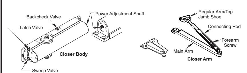
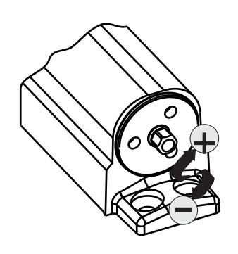
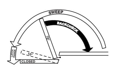
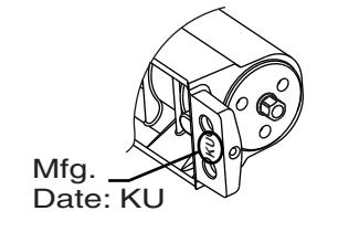
Valve Adjustments
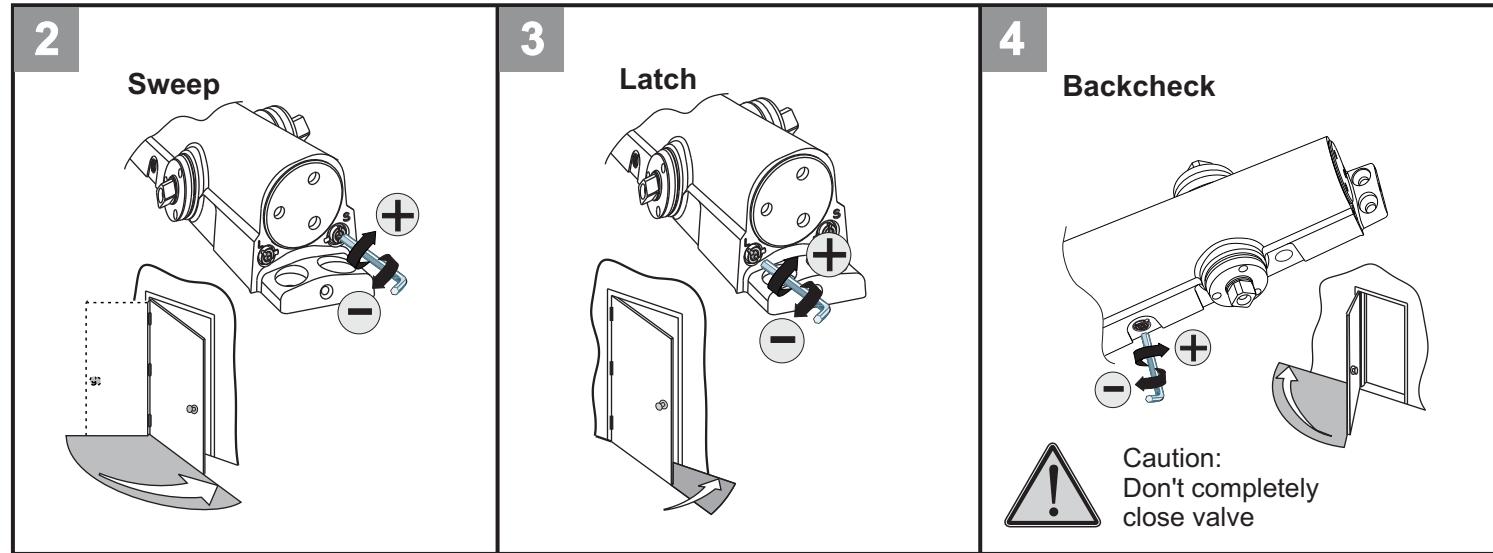

Adjust Closing Speed Time to between 3 to 7 seconds from 90°. Use of the door by handicapped, elderly or small children may require greater closing time.
63-8174-6000-999
Copyright © 2013 Sargent Manufacturing Company, an ASSA ABLOY Group company. All rights reserved. Reproduction in whole or in part without the express written permission of Sargent Manufacturing is prohibited. A8174A