Installation Instructions for 11 Line with High Security Lever Attachment (SL- option)
Open the original PDF document
View PDFInstallation Instructions

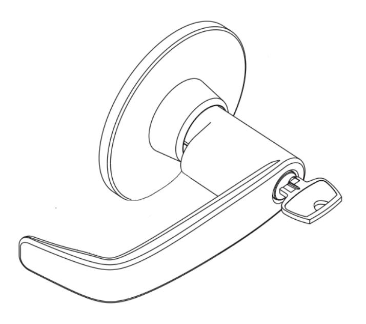
11 Line
with High Security Lever (SL-) Attachment Bored Lock
Note
- Factory assembled for either right or left hand doors. Correct hand to match door application.
- Improper installation may result in damage to lock and void factory warranty.
- Other product brand names may be trademarks or registered trademarks of their respective owners and are mentioned for reference only.

This product can expose you to lead which is known to the state of California to cause cancer and birth defects or other reproductive harm. For more information go to www.P65warnings.ca.gov.

| TOC | Table of Contents |
|---|---|
| 1 | Lock Body Assembly 2 |
| 2 | Security Attachment Screw 2 |
| 3 | Lever Installation 3 |
| 4 | Cylinder Removal 3 |
| 1 | Lock Body Assembly |
- 1. Prep door, and install lock bearing and latch according to T-Zone Installation Instructions A7469, steps 1through 5.
- 2. Complete assembly of lock with Security Lever Attachment, according to the following steps.
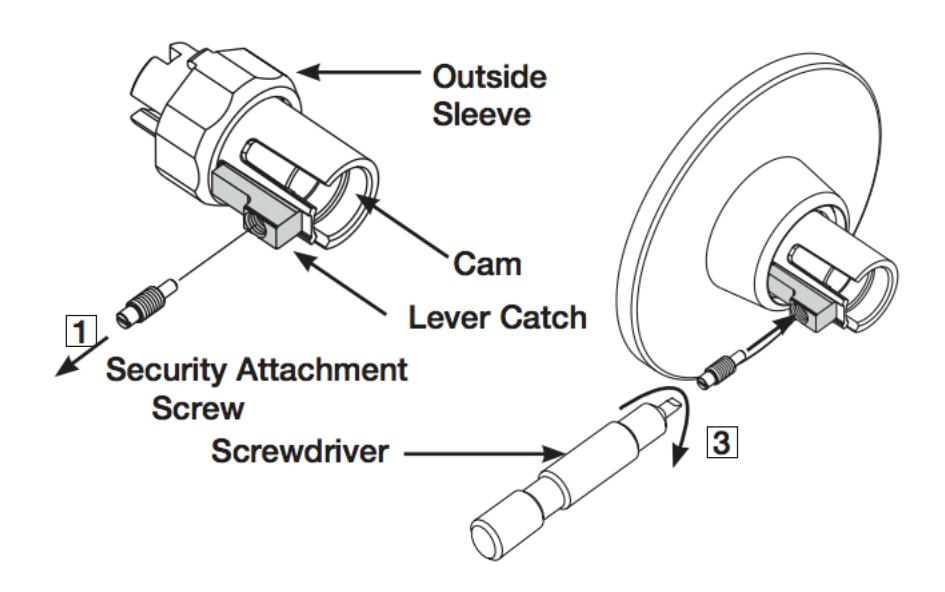
2 Security Attachment Screw
- 1. Using screwdriver provided, unscrew the Security Attachment Screw from lever catch on the outside sleeve.
- IMPORTANT Keep screw for reinstallation.
- 2. Install outside and inside sleeves and roses according to Installation Instructions A7469, steps 6 & 7.
- 3. PLEASE NOTE THE CAM IN THE OUTSIDE SLEEVE MUST BE ROTATED SO THE LARGE SLOT IS HORIZONTAL. THIS ALLOWS THE SECURITY SCREW TO THREAD INTO THE CAM. Insert the Security Attachment Screw into black lever catch assembly and tighten until screw head is within approximately 1/8" of black lever catch. DO NOT OVER TIGHTEN.

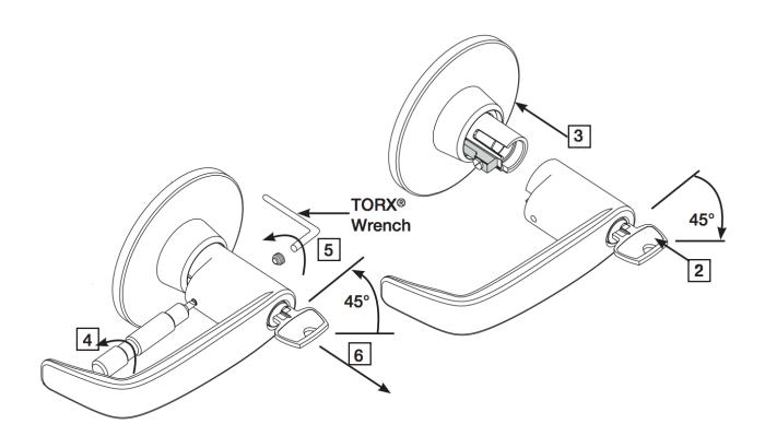
3 Lever Installation
- 1. IMPORTANT: Before installing levers read, "SPECIFIC INSTRUCTIONS PER FUNCTION BEFORE INSTALLING LEVER" on page 4 of T-Zone Installation Instructions A7469.
- 2. Place cylinder in outside lever. Insert key and rotate 45 degrees clockwise.
- 3. With key rotated, push lever onto sleeve until hole on inside of lever is over Security Attachment Screw. If screw interferes with assembly, check that screw is fully threaded into black lever catch.
- 4. Using screwdriver provided, rotate Security Attachment Screw counter-clockwise until flush with the surface of the lever.
- 5. Secure lever with 6 lobe security screws. Screws should be flush when properly tightened.
- 6. Rotate key to horizontal and remove.
- 7. Assemble inside lever and secure with 6 lobe TORX® security screws.
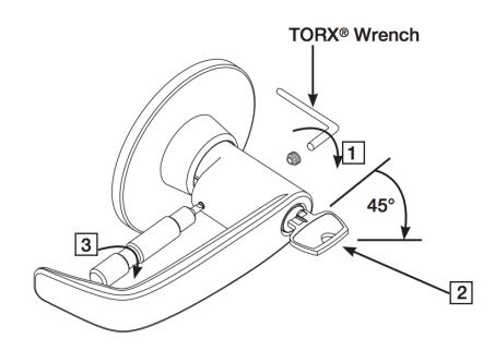
4 Cylinder Removal
- 1. Remove the security screw on the outside of the lever with TORX® wrench.
- 2. Insert key and rotate key 45º clockwise. Keep key in this position .
- 3. Using screwdriver, tighten the Security Attachment Screw clockwise until it clears the lever.
- 4. Remove lever and remove key.
- 5. Remove cylinder from lever and install new cylinder.
- 6. Reinstall lever, following step 3 above.
The ASSA ABLOY Group is the global leader in access solutions. Every day, we help billions of people experience a more open world.
ASSA ABLOY Opening Solutions leads the development within door openings and products for access solutions in homes, businesses and institutions. Our offering includes doors, frames, door and window hardware, locks, perimeter fencing, access control and service.
SARGENT Manufacturing Company 100 Sargent Drive New Haven, CT 06511 USA 800-727-5477 www.sargentlock.com