Installation Instructions for 10 Line Lever Locks
Open the original PDF document
View PDFInstallation Instructions

10 Line Cylindrical Lockset
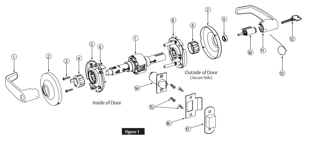
1 Package Contents
| Figure 1 | Description | Req |
|---|---|---|
| 1 | Inside Lever | 1 |
| 2 | Rose Scalp | 2 |
| 3 |
Screws – mounting
plate #6 x 3/4" self tapping |
2 |
| 4 | Spacer bushing | 2 |
| 5 | Inside rose assembly | 1 |
| 6 |
Screws – through
bolt #10-32 x 1-1/4" |
2 |
| 7 | Lockbody | 1 |
| 8 |
Outside rose
assembly |
1 |
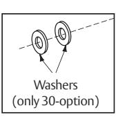
| 9 | Cylinder spacer | 1 |
| 10 | Cylinder | 1 |
| 11 | Outside lever | 1 |
| 12 | Key | 1 |
| 13 | Push pin | 1 |
| 14 | Latch | 1 |
| 15 |
Screws – latch &
strike #8-32 x 3/4" |
4 |
| 16 | Strike | 1 |
| 17 | Strike box | 1 |
Tools Required
- #2 Phillips screwdriver
- Flat-bladed screwdriver
- Push pin (provided)
- 7/16" drill bit • 1" Bore
- 1/8" drill bit
- 2-1/8" Bore
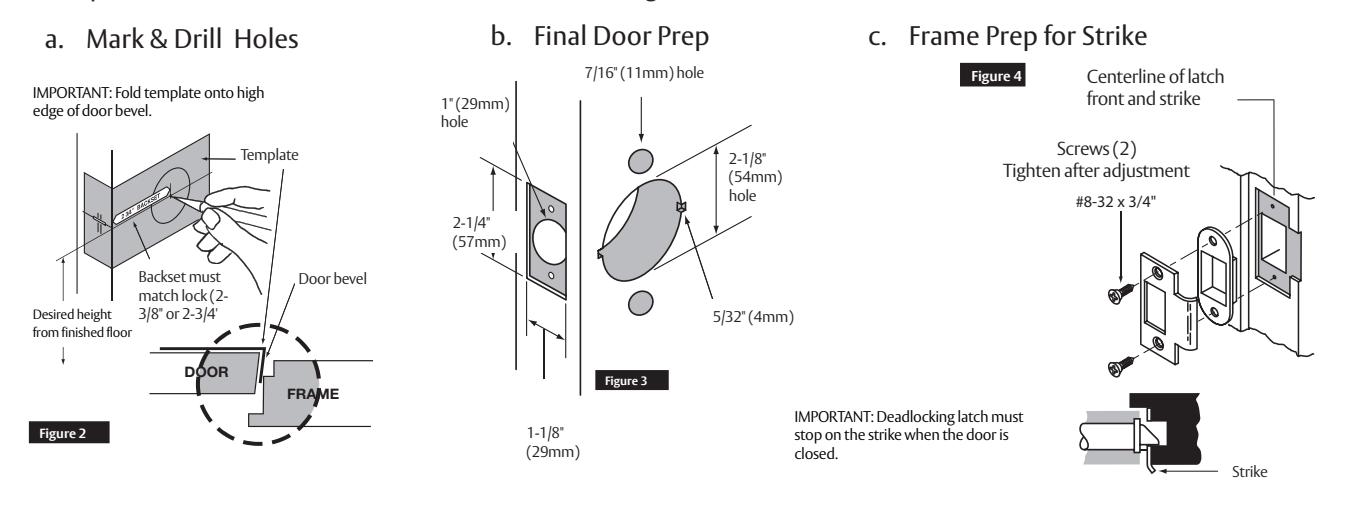
2 Door Preparation
- All doors should be properly reinforced for lock support. If support is not provided, contact door manufacturer.
- For all metal door preparations, use template A4375 (Not included. See website to download), EXCEPT for functions 10G70 or 10G71 which use template 4409 (not included), or functions 10U93, 10U94, and 10U94-2 which require template A4375.
- For all wood door preparations use template A6719 (included), EXCEPT for functions 10G70 & 10G71.
- Template information is available on our website: www.sargentlock.com.
10 Line
Cylindrical Lockset
Installation Instructions

3 Latch Installation
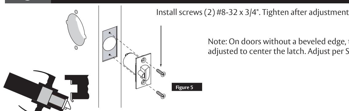
Note: On doors without a beveled edge, the lock needs to be adjusted to center the latch. Adjust per Section 5.
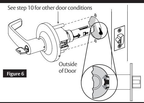
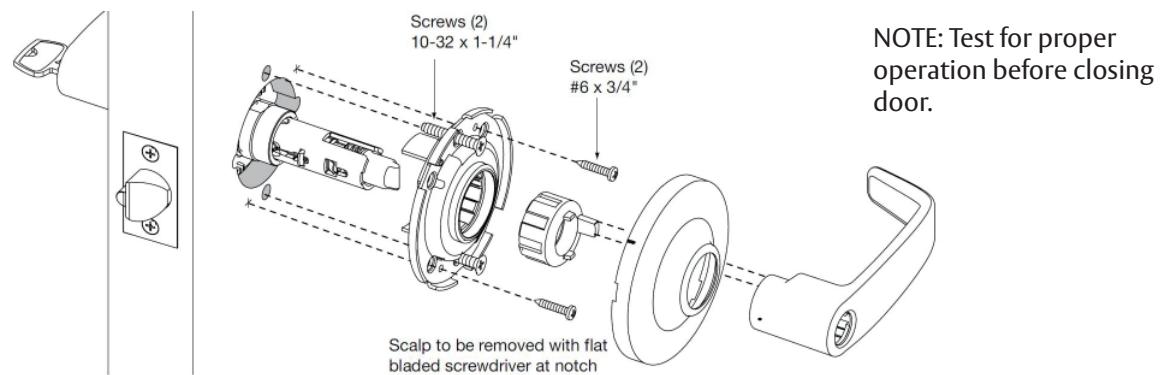
4 Install Outside Assembly
Presets:
- Through-bolt location: 12 and 6 o'clock. (Figure 6)
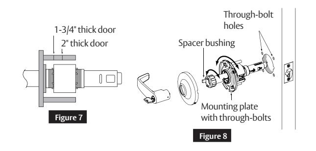
- Door Thickness: 1-3/4" thick.
5 Through-bolt and door thickness adjustment other than preset
- Remove outside lever (usually keyed), rose and spacer bushing. (Figure 8)
- Rotate mounting plate to align with through-bolt holes in door, or adjust mounting plate for proper door thicknesses (see markings on Figure 7).
- Reinstall spacer bushing to align with back of lever. Reinstall scalp and lever.
- For doors 1 3/8" thick, use the 10-3188 adapter kit sold separately. Confirm latch bolt front size.
6 Install Inside Rose Assembly, Scalp and Lever
1-800-727-5477 • www.sargentlock.com A7133 12/20
10 Line
Cylindrical Lockset
Installation Instructions
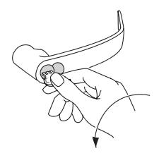
7 Lever Removal & Installation
Standard Cylinder (Figure 9)
To Remove:
Rotate key 45° and hold. Depress lever catch with pin tool.
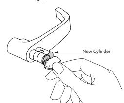
To Install:
Insert key and rotate 45° clockwise, slide the lever on. Confirm the lever will not pull off.
Interchangable or Removable Core (Figure 10)
To Remove:
Remove cylinder and tailpiece, using control key (stamped "C"). Insert Phillips #2 screwdriver into cylinder opening and make contact with lever catch. Pull lever catch horizontally towards door hinge and remove lever.
To Install:
Slide lever over lever catch. Confirm the lever will not pull off.
*Note: For 1-Bitted cylinders, utilize a control key cut 113511.
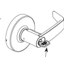
Figure 9
Lever catch

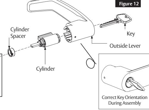
8 Standard Cylinder Installation
IMPORTANT
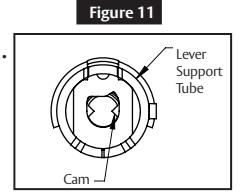
10G16, 10G30, 10G54 Functions:
• Before installing cylinders, use a flat-bladed screwdriver to rotate all cams counterclockwise until they stop (Figure 11). (Cam is located in lever support tube of lockbody). (Figure 12)
10G26 & 10G38 Functions:
• See supplemental instruction sheet A8082.
Interchangeable or Removable Core
- Remove temporary construction core or plastic core. If keyed, use Control Key (stamped "C") rotate 15° and pull.
- Insert permanent core into lever with control key; rotate 15° and remove key.

IMPORTANT
- Remove tailpiece from construction core and insert into new core. If using 7 pin cores, insert the 7 pin tail piece that's supplied with the lock, before installing the core into the lock.
- For Degree and XC LFIC cores, retainer must be installed on tailpiece.
SFIC Shown

Figure 13
10 Additional Installations
1. Remove 10G13 (Figure 13)
- Remove inside (non-rigid) lever with a standard push pin.
- Insert long push pin into lockbody tube and push to release spring-loaded lever catch plug assembly for outside lever.
- Remove outside lever with lever catch plug assembly attached.
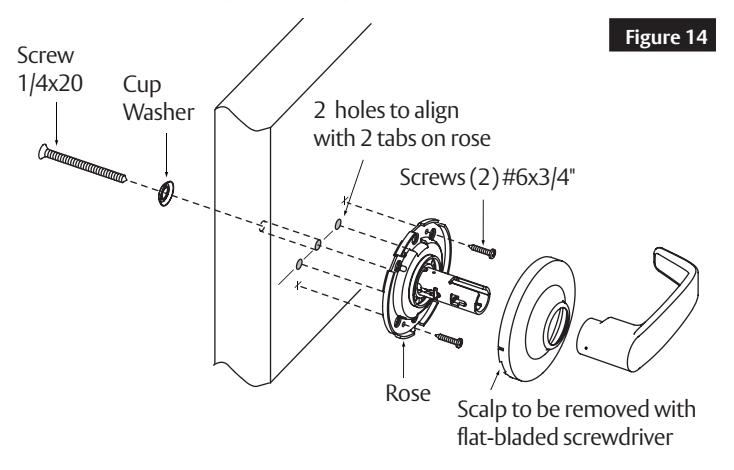
2. Install 10U93 (Figure 14)
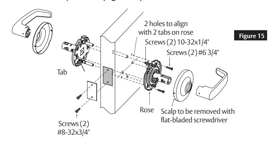
3. Install 10U94/10U94-2 (Figure 15)
SARGENT Manufacturing Company 100 Sargent Drive New Haven, CT 06511 USA 800-727-5477 www.sargentlock.com