Installation Instructions – S6800 CVR Delayed Egress
Open the original PDF document
View PDF

801 Avenida Acaso, Camarillo, Ca. 93012 • (805) 494-0622 • www.sdcsecurity.com E-mail: service@sdcsecurity.com
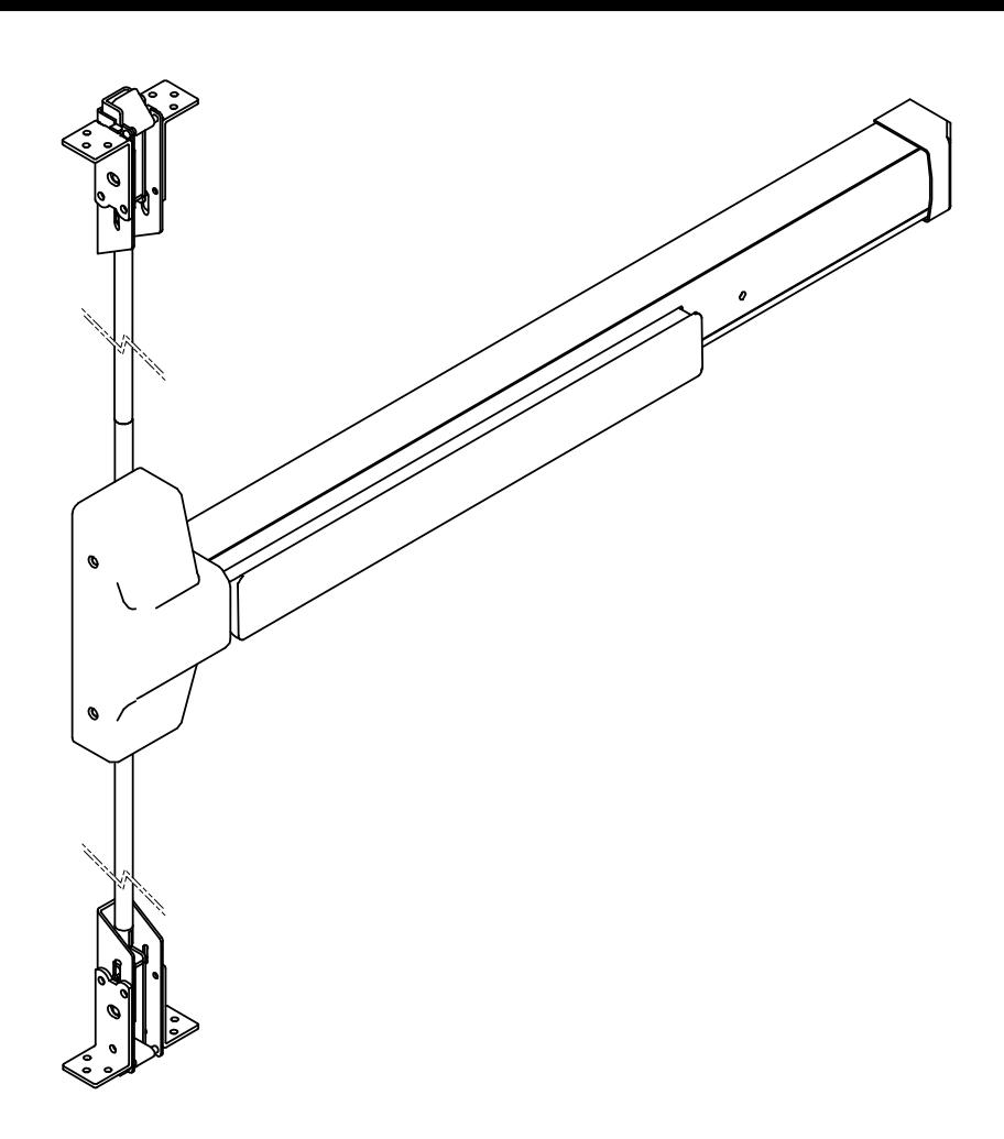
INSTALLATION INSTRUCTIONS S6800 SERIES PANIC/FIRE EXIT CONCEALED VERTICAL ROD DEVICES
These instructions are presented in a step by step sequence.
Please read it through before installation.
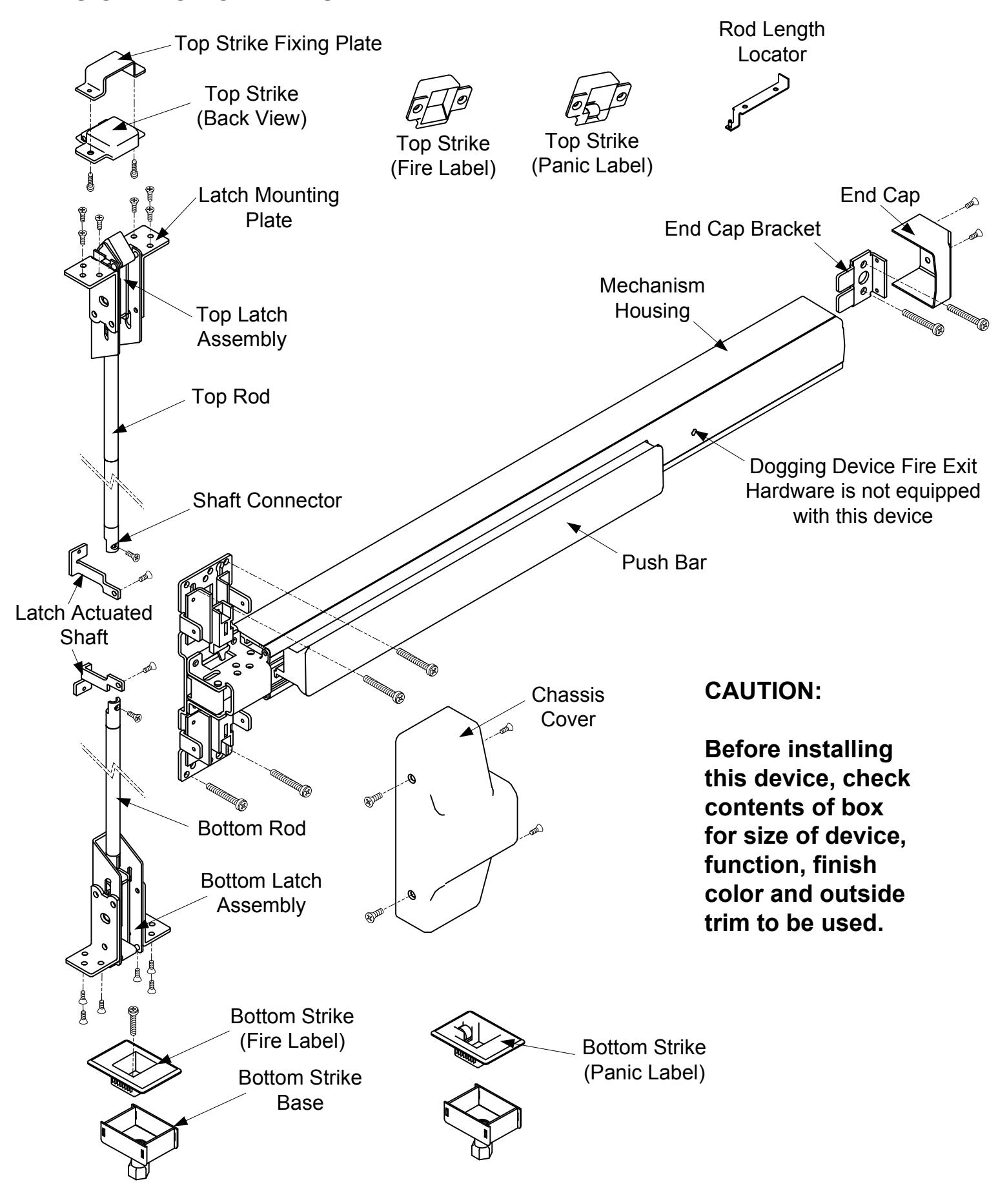
DESIGNATION OF PARTS
A. PREPARE DOOR 1. Mark centerline of device by drawing a line across the door. 2. Mark a backset line and 4 thru holes for device chassis shown on the template provided. 3. Prepare the door cut-outs by using the template provided. The centerline of the device must be 40" above the finished floor. Bottom Door gap MUST be 1/4". 2-7/16" of Device CL Mark backset from edge of door INSIDE FACE OF DOOR Drill holes and cut-outs on the Device side ONLY of Device CL 39-3/4" See Trim Installation Instructions for outside face of door preparation. Figure 1-1
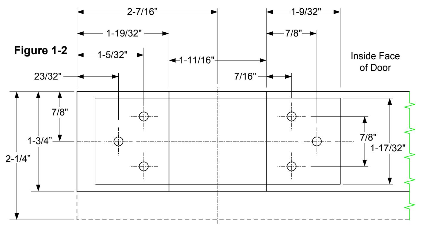
- 4. Cut out the top edge and bottom edge of the door, then weld two 5mm thick mounting plates on both edges for Top and Bottom Latch Assemblies (figure 1-2).
- 5. Drill holes and tap for M5 X 10 threads on the mounting plates on the top and bottom of door.
B. ASSEMBLE RODS AND LATCHES
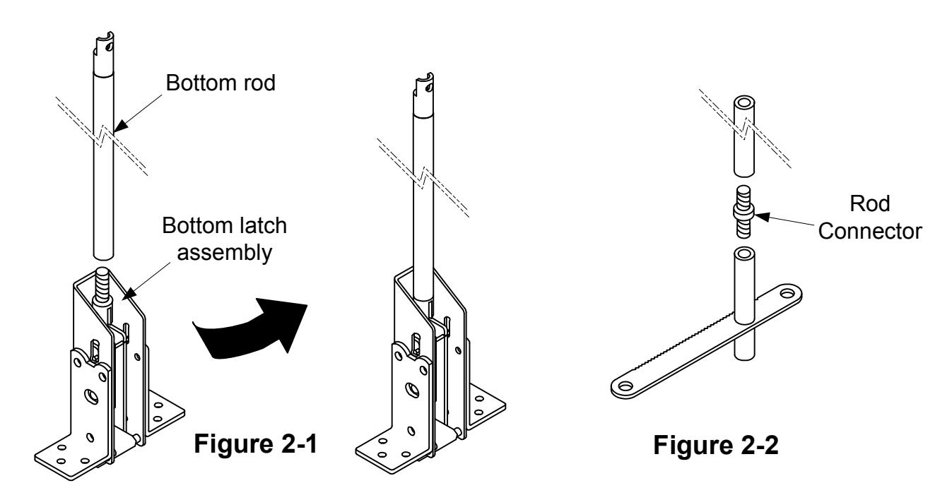
- 1. Screw bottom rod into bottom latch assembly (figure 2-1).
-
2. Assemble top rod:
- 2-1 Connect short top rod to long top rod using rod connector (figure 2-2).
- 2-2 Measure and cut the length of the top rod if it is too long.
- 2-3 Insert shaft connector into the non-threaded end of the top rod and tighten screw to fix in place (figure 2-3).
- 3. Screw top rod assembly into top latch assembly (figure 2-4).
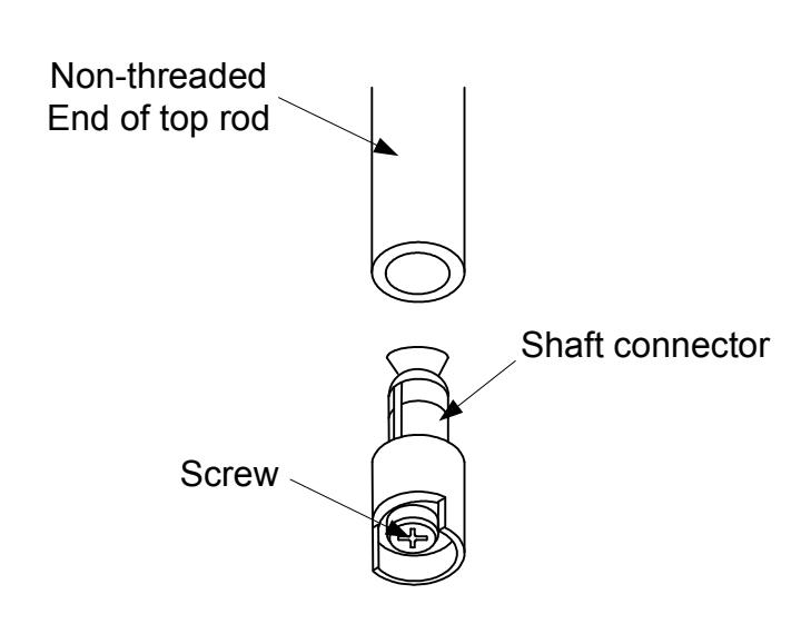
Figure 2-3
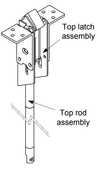
Figure 2-4
C. MOUNT LATCH ASSEMBLIES
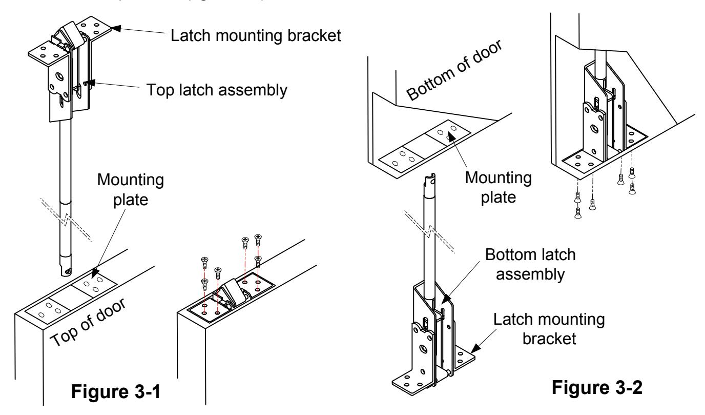
- 1. Attach latch mounting brackets to top and bottom latch assemblies
- 2. Insert top latch assembly into top of the door and fasten to the mounting plates with the screws provided (figure 3-1).
- 3. Insert bottom latch assembly into bottom of the door and fasten to the mounting plates with the screws provided (figure 3-2).
D. ADJUST VERTICAL RODS
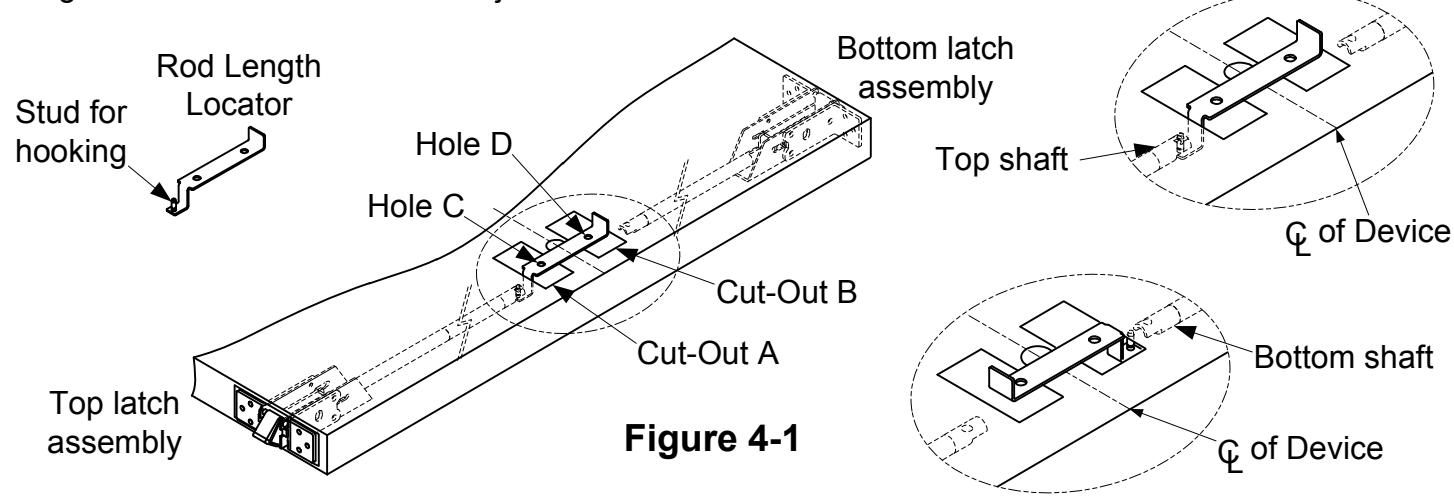
1. Place the rod length locator through the cut-outs on the inside face of the door. Hook a shaft connector with the small stud on the locator. When the shaft connector is raised to as level as possible, the holes C or D in the locator should align with the cut-outs A or B (figure 4-1).
2. If the C or D holes in the locator do not align with their respective cut-out, then the vertical rod length is incorrect and must be adjusted.
Rev A
01/13 Page 5
3. Adjustment procedure:
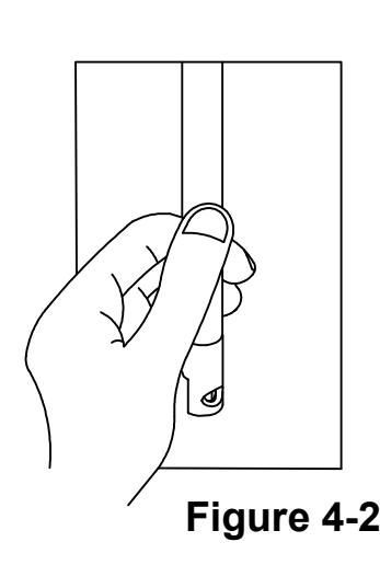
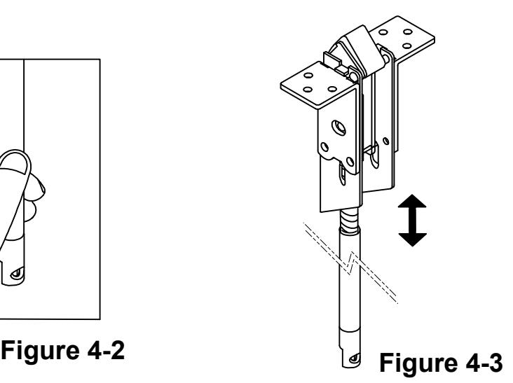
Adjust the length of the two vertical rods by hand through the cut-outs (figure 4-2). Shorten or lengthen the rods by turning into or out of the latch assemblies (figure 4-3) until the holes of the shaft connectors are in the proper position as determined by the latch length locator (pg. 5, figure 4-1).
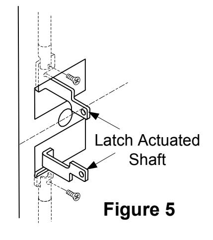
E. INSTALL LATCH ACTUATOR SHAFTS
- 1. Attach one Latch Actuated Shaft to the top and bottom shaft connectors (figure 5) with screws supplied.
- 2. Make sure both top and bottom latch actuated shafts are parallel.
F. INSTALL DEVICE AND TRIM (if applicable)
- 1. Remove device chassis cover from the chassis assembly and the end cap from the end cap bracket.
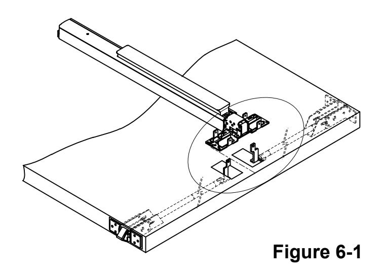
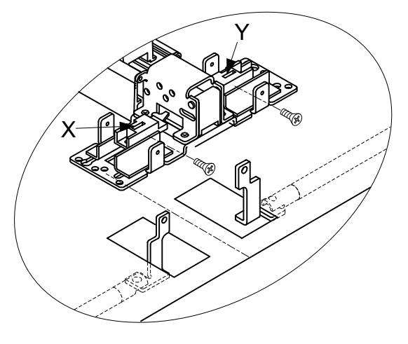
- 2. Position the device on the door and insert latch actuated shafts into the slots marked "X" and "Y" (figure 6-1). Fasten in place with screws supplied.
-
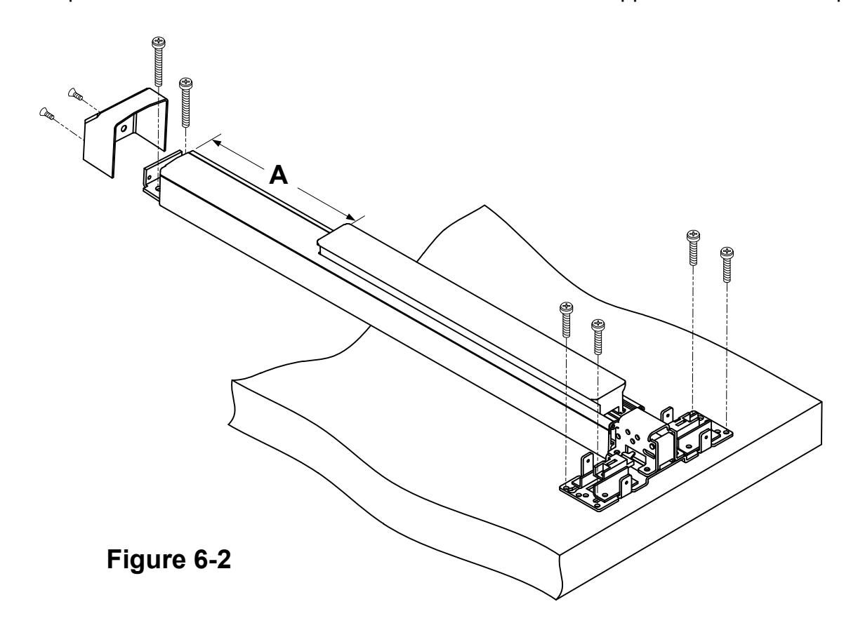
3. Cut the length if required:
- a. The device length is pre-cut for use on 36", 42" or 48" wide doors, no additional cutting is necessary. If narrow door installation is required, cut device at section "A" to door width minus 2" for proper fit.
- b. Remove device from door, remove end cap and end cap bracket and cut where required. NOTE: Device must be cut flat with all burrs removed for end cap to fit properly.
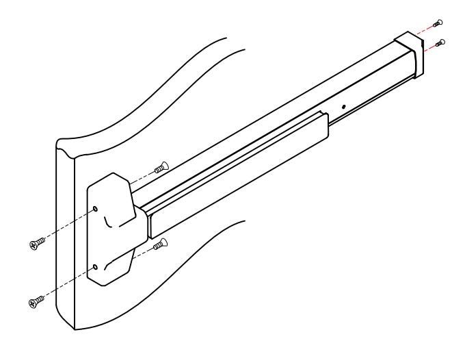
- 4. Mount device horizontally via the drilled holes and secure with supplied mounting hardware. Attach device to trim or sexbolt (if applicable).
- 5. Install end cap bracket to device and attach to door with hardware supplied. Attach end cap.
G. TEST OPERATION AND HANG DOOR.
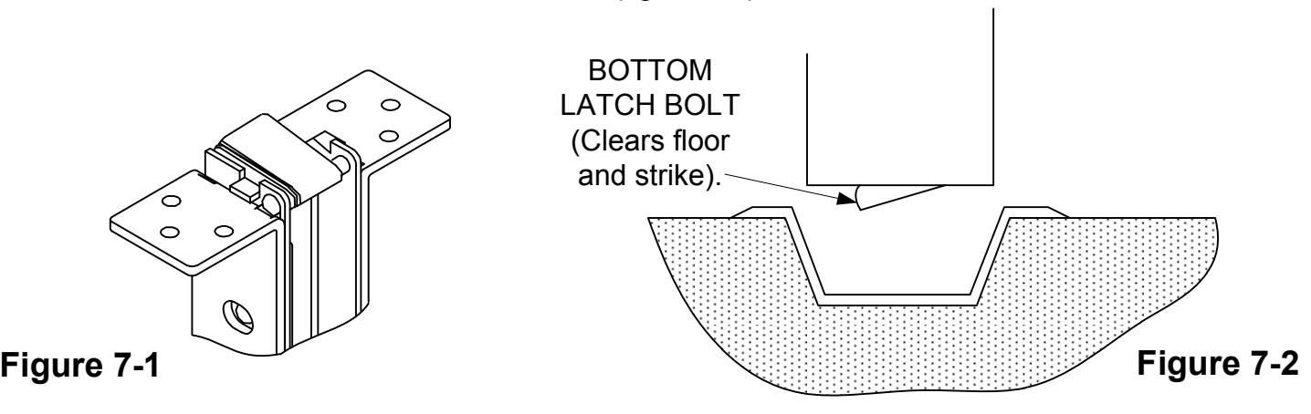
1. Depress push bar. Top latch bolt should be retracted as shown (figure 7-1) and bottom latch clears floor and bottom strike (figure 7-2).
2. Release push bar, Make sure both top and bottom latch bolts are FULLY extended
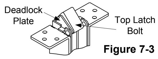
3. Check top latch bolt for deadlocking function. Depress the deadlock plate by hand. When the deadlock plate is depressed, the latch bolts should be locked in the extended position and unable to be pressed down (figure 7-3).
- 4. Check device operation by depressing and releasing push bar several times to assure correct final installation.
- 5. Hang door (with device installed) and repeat operation check with outside lever.
- 6. redo rod length adjustment if either top latch bolt is not held retracted or if the bottom latch bolt does not clear the floor and bottom strike.
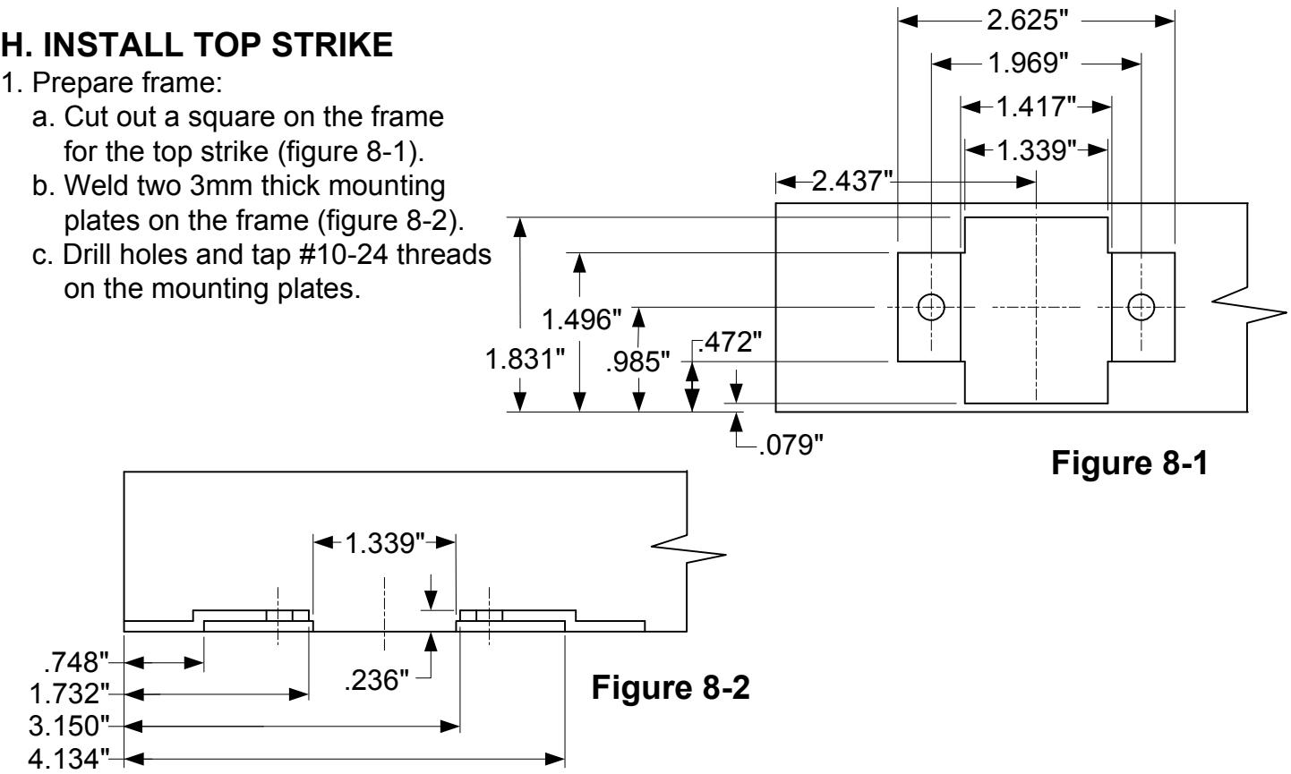
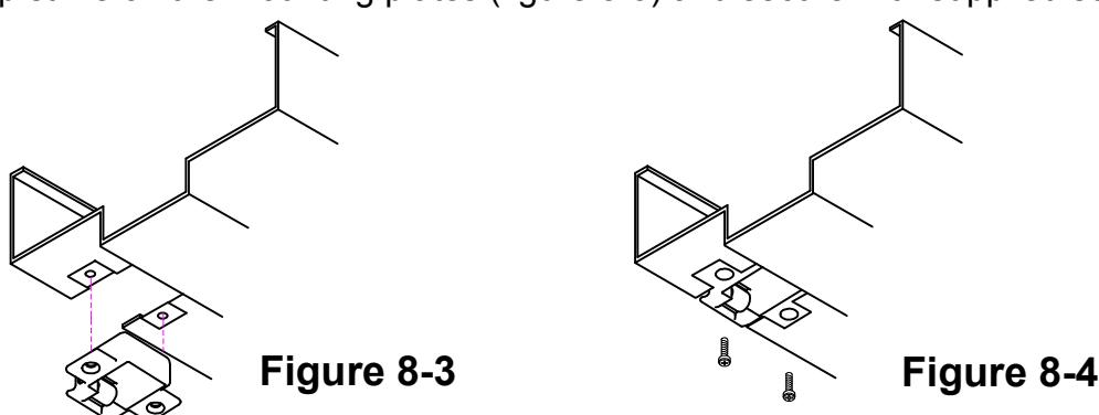
2. Install the top strike on the mounting plates (figure 8-3) and secure with supplied screws (figure 8-4).
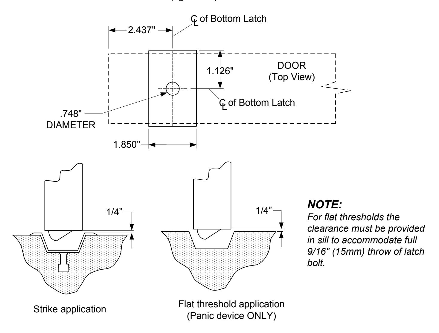
I. INSTALL BOTTOM STRIKE
- 1. Bore the hole into the finished floor or threshold (figure 9-1).
- 2. Install bottom strike into the hole (figure 9-2).
J. INSTALL COVERS
-
1. Test push bar operation before installing covers;
- a. No Trim: Latch bolts are retracted by the push bar inside.
- b. With Trim: Latch bolts are retracted by the push bar inside, key or lever/knob outside.
- c. Dogging: See dogging description and chart page 10.
- 2. Check latch bolt engagement, adjust strikes if required.
- 3. Install chassis cover over chassis assembly.
- 4. Install end cap.
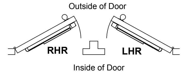
Door Handing
Use this diagram to determine the hand of door.
NOTE:
To extend the life of this device, it is recommended to activate the dogging feature during high traffic periods of the day.
Dogging:
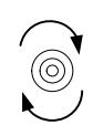
Insert dogging wrench and turn clockwise 15 degrees.
Depress Push Bar
The push bar will remain pressed and the latches will remain retracted.

Release Dogging:
Insert dogging wrench and turn counter-clockwise 15 degrees.
Depress Push Bar
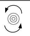
The push bar will return to the up position and the latches will extend to lock the door.