Installation Instructions – S6200 SVR
Open the original PDF document
View PDF

801 Avenida Acaso, Camarillo, Ca. 93012 • (805) 494-0622 • www.sdcsecurity.com E-mail: service@sdcsecurity.com
S6200 SERIES PANIC/FIRE EXIT SURFACE MOUNTED VERTICAL ROD DEVICES
INSTALLATION INSTRUCTIONS
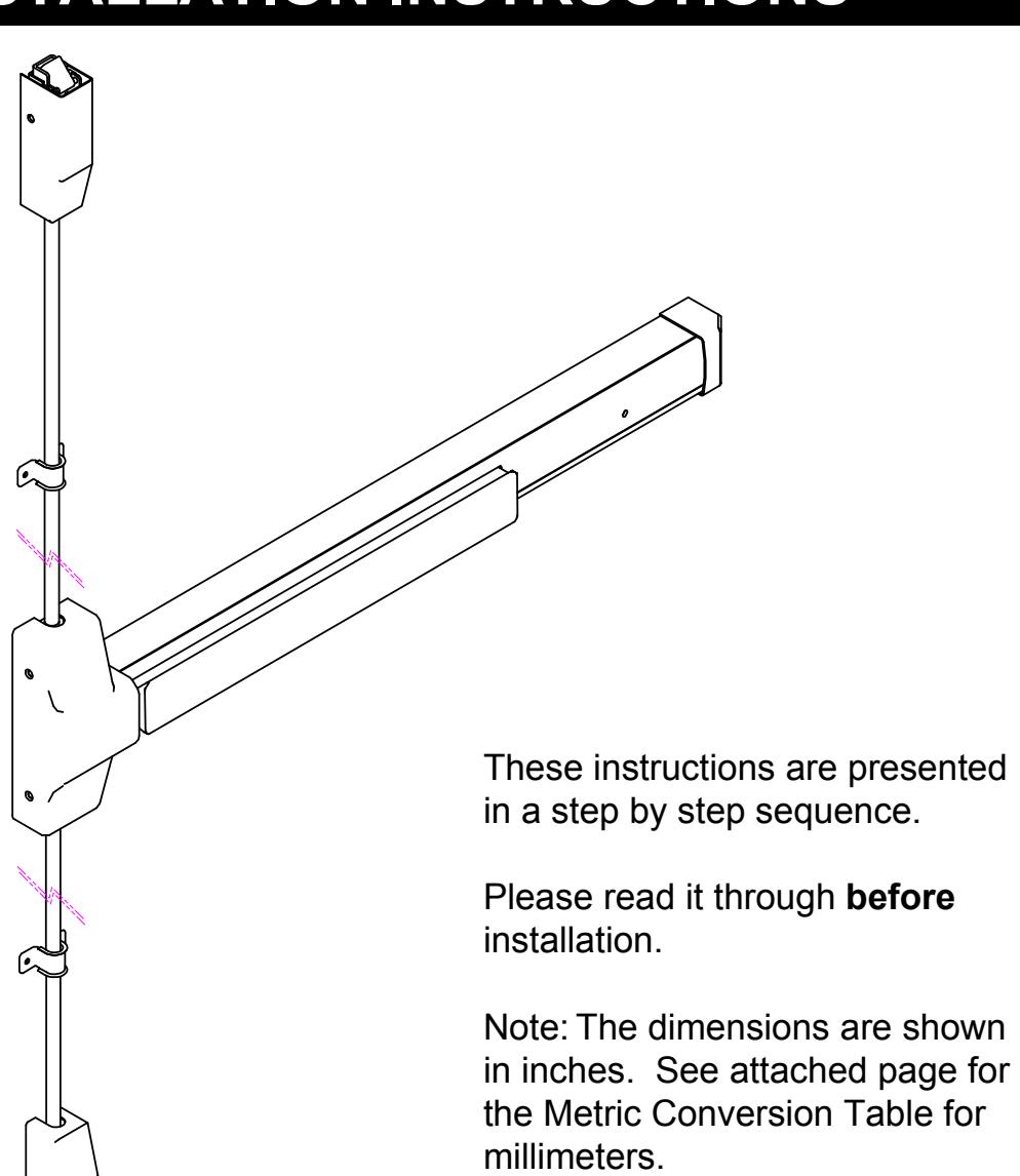
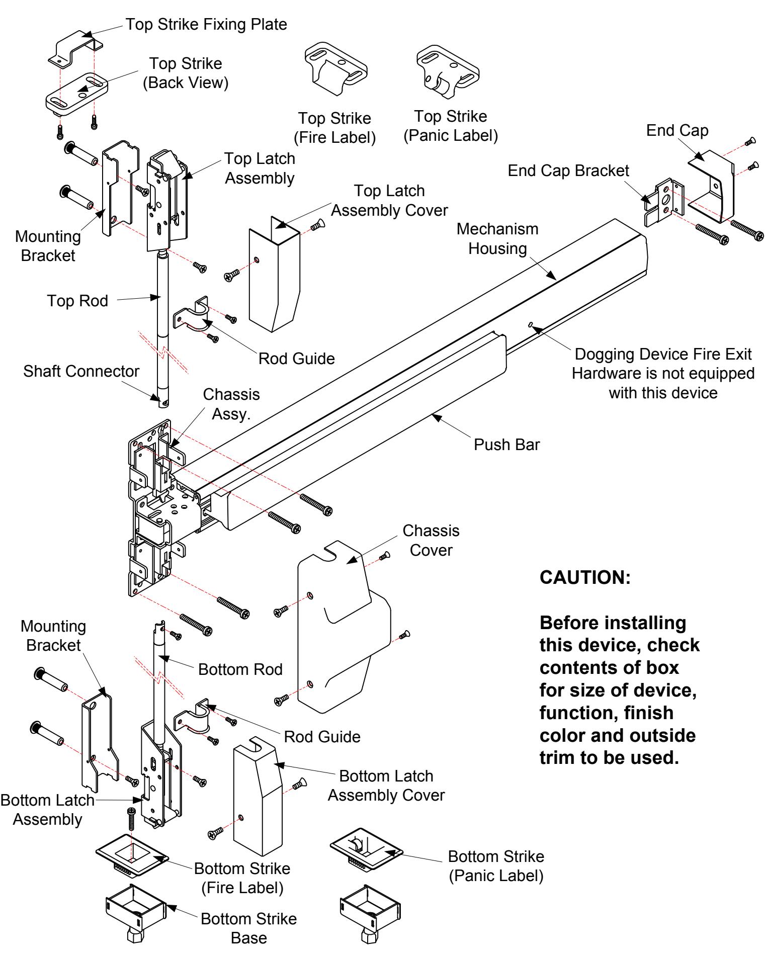
DESIGNATION OF PARTS
STEP 1: PREPARE DOOR
- 1. Mark position of holes on the door per template (see figure 1).
- 2. Drill all holes marked on the door for the device chassis and top and bottom latch mounting brackets.
- 3. Mortise hole for outside trim is required.
NOTE; Any hole drilled from the outside, first needs a pilot hole drilled from the inside to ensure good alignment.
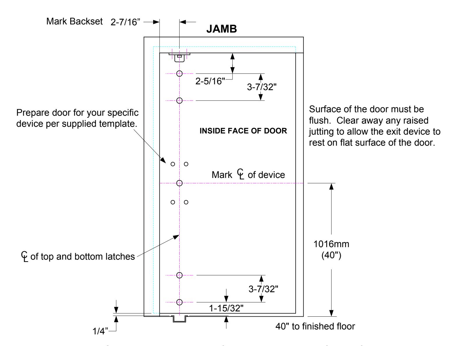
Standard centerline height of device is 40" above the finished floor.
Figure 1
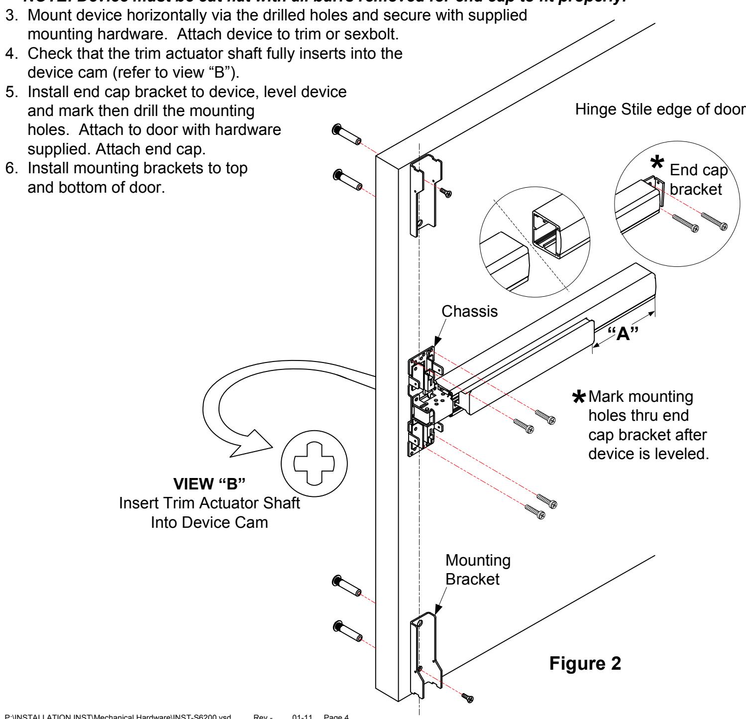
STEP 2: INSTALL BRACKETS, DEVICE & TRIM
- 1. Remove chassis cover from chassis assembly and end cap from end cap bracket.
- 2. Cut the length if required.
For user information; This model device has three different lengths:
For use on 3' wide door, device = 33"
For use on 3.5' wide door, device = 40"
For use on 4' wide door, device = 44"
- a. The device length is pre-cut for use on 36", 42" or 48" wide doors, no additional cutting is necessary. If narrow door installation is required, cut device at section "A" to door width minus 2" for proper fit.
- b. Remove device from door, remove end cap and end cap bracket and cut where required.
NOTE: Device must be cut flat with all burrs removed for end cap to fit properly.
STEP 3: INSTALL BOTTOM ROD AND BOTTOM STRIKE
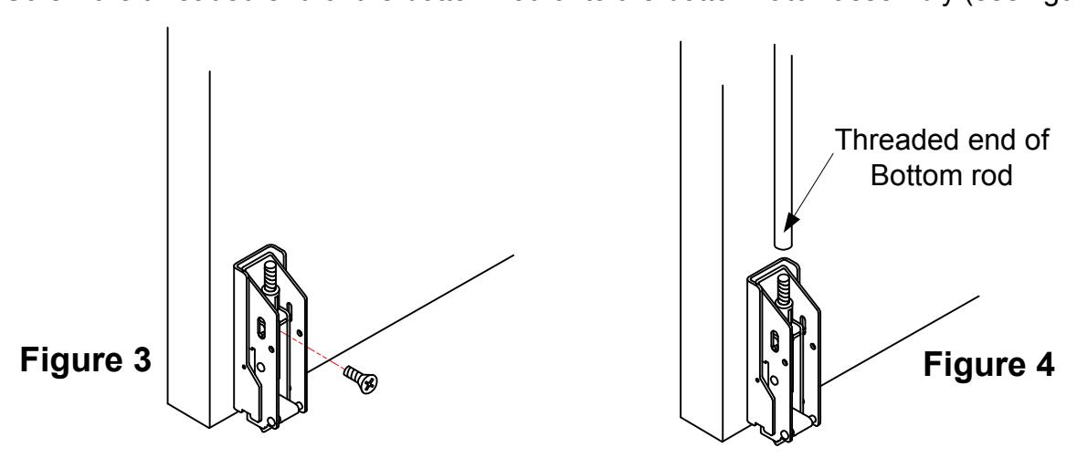
- 1. Mount the bottom latch assembly into the mounting bracket (see figure 3).
- 2. Screw the threaded end of the bottom rod onto the bottom latch assembly (see figure 4).
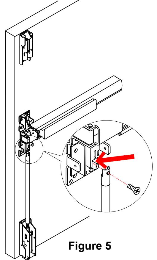
3. Using screw supplied, attach and tighten the bottom rod to the chassis at the location indicated by the arrow in figure 5.
NOTE: If the hole on the bottom shaft connector does not align with the mounting hole in the chassis, adjust the length by turning the rod in or out of the latch assembly.
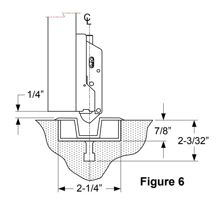
4. Install bottom strike into finished floor or threshold, and be sure to align center line of bottom latch with the centerline of the bottom strike (see figure 6)
- 5. Depress and release push bar to confirm proper installation.
- 5-1 Make sure bottom latch can be retracted and flush with the edge of the door when push bar is depressed.
- 5-2 Check bottom latch bolt has 19/32" (15mm) throw min. when push bar is released.
STEP 4: INSTALL TOP ROD AND TOP STRIKE
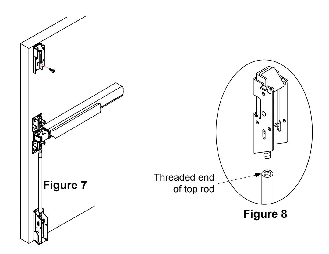
- 1. Mount the top latch assembly into the mounting bracket (see figure 7).
- 2. Screw the threaded end of the top rod onto the top latch assembly completely (see figure 8).
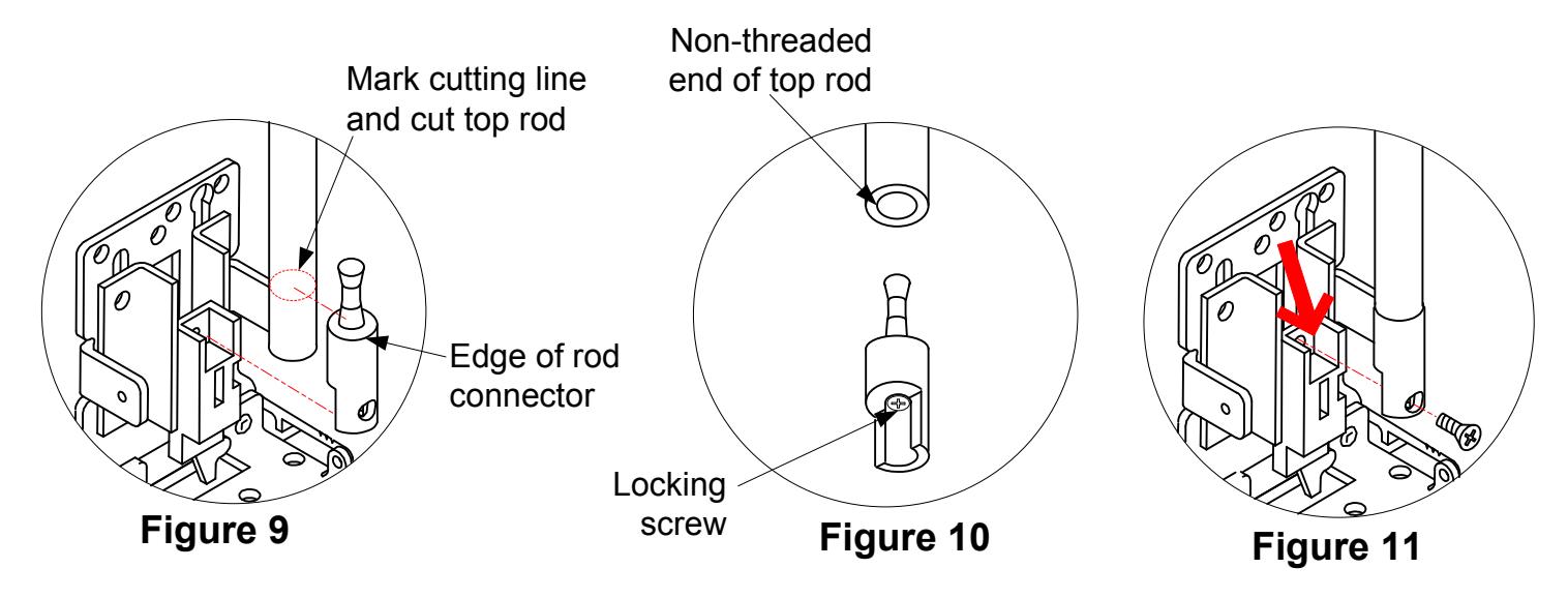
- 3. Measure and cut the length of the top rod. The length of the top rod is measured to the edge of the rod connector (see figure 9) which will be attached to the chassis.
- 4. Insert the rod connector into the non-threaded end of the top rod and secure in place by tightening the locking screw (see figure 10).
- 5. With the top rod connector installed, attach the top rod to the chassis at the location indicated by the arrow (see figure 11).
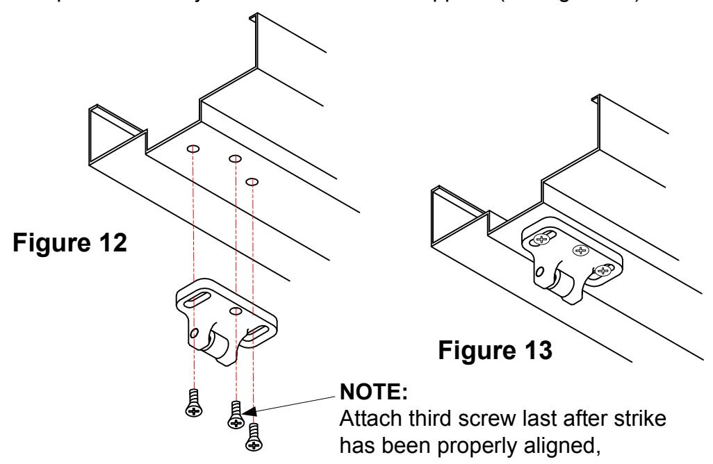
6. Mark and drill mounting holes on the jamb for the top strike per the strike template (see figure 12). Fasten the top strike to the jamb with the screws supplied (see figure 13).
STEP 5: TEST OPERATION
- 1. Depress the push bar. The top and bottom latches should be held retracted. The bottom latch should also clear the floor and the bottom strike. Door can now be opened.
- 2. Release push bar, both the top latch bolt and the bottom latch bolt should be fully extended.
- 3. Check device operation by depressing and releasing push bar several times to assure final installation is correct.
4. Repeat device operation by opening and closing door several times using the outside trim to make sure all installations have no problems.
5. Repeat adjustment procedure if either the top latch bolt is not held retracted, or bottom latch bolt does not clear floor and bottom strike.
STEP 6: INSTALL COVERS
- 1. Before installing covers, check and secure top and bottom latch bolts engagement. Adjust strikes if necessary.
- 2. Install the chassis and top & bottom assembly covers and the two rod guides (see figure 14).
Figure 14
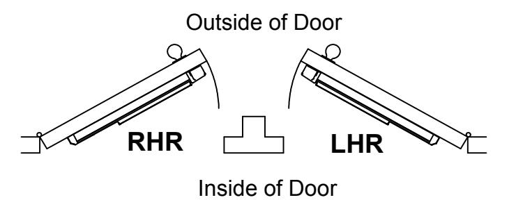
Door Handing
Use this diagram to determine the hand of door.
NOTE:
To extend the life of this device, it is recommended to activate the dogging feature during high traffic periods of the day.
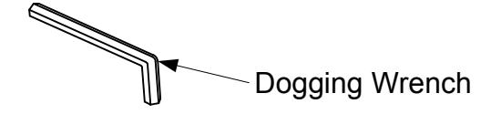
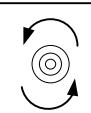
Dogging:
Insert dogging wrench and turn clockwise 15 degrees.
Depress Push Bar
The push bar will remain pressed and the latches will remain retracted.
Release Dogging:
Insert dogging wrench and turn counter-clockwise 15 degrees.
Depress Push Bar
The push bar will return to the up position and the latches will extend to lock the door.