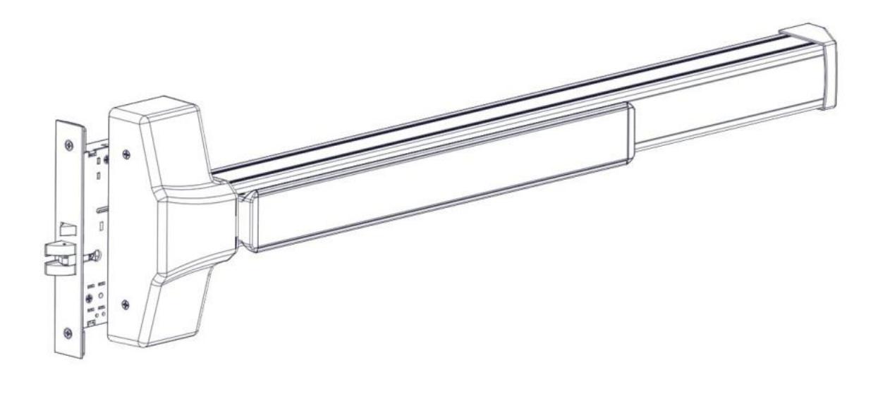
Installation Instructions (Rev 2 product only) – I-ED01553-Rev6
Open the original PDF document
View PDF


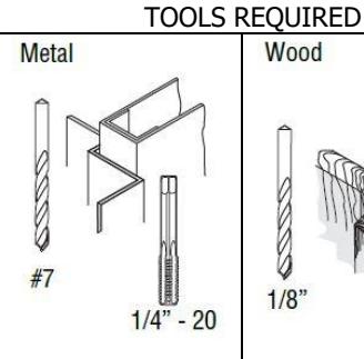
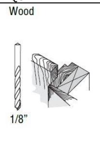
Wood and Metal Screws For wood doors, drill
1/8" hole Machine Screws
Canada S #7 drill, 1/4" - 20 tap
Sex Bolts
Check building and fire codes to see if your application requires the use of sleeve nuts and bolts.
DOOR HANDING OUTSIDE OF DOOR
RHR LHR INSIDE OF DOOR
Rev 6, Rev Date: 12/12/24 Page 1 of 10

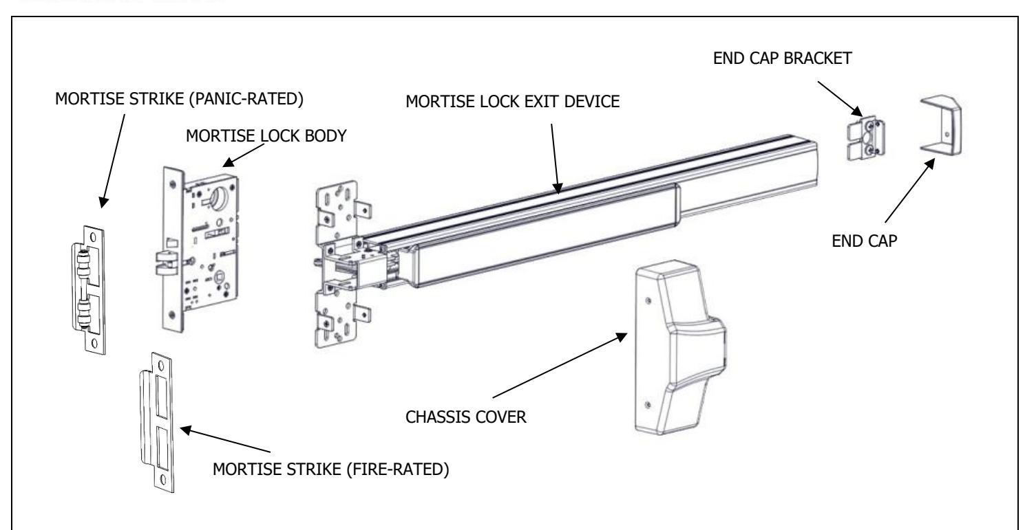
| Fasteners and Other Parts Included | Qty. | Purpose |
|---|---|---|
| ¼"-20 x ¾" Pan Head Machine Screws | 4 | Through-bolting to wood or metal doors or surface mounting to metal |
| doors | ||
| #12 x 1.25" Wood Screws | 4 | Surface mounting to wood doors |
| Hex Dogging Wrench | 1 | Used to dog the device |
| Mortise Lock Armor Plate | 1 | Protects mortise lock body |
| M4 x 0.7 x 6 Flat Head Machine Screw | 2 | Fastening the armor plate to the mortise lock |
| #12 Combination Wood/Metal Screw | 4 | Fastening the strike to the frame and the mortise lock body to the door |
Rev 6, Rev Date: 12/12/24 Page 2 of 10

1. CUT EXIT DEVICE TO LENGTH
The exit device comes in two models, one sized for a 36" door width and one sized for a 48" door width. For other door widths, cut the exit device to the appropriate length. Recommended overall length of the exit device is equal to the door width minus 4 inches. Cut with a hack saw or metal cutting saw blade. Deburr edges.
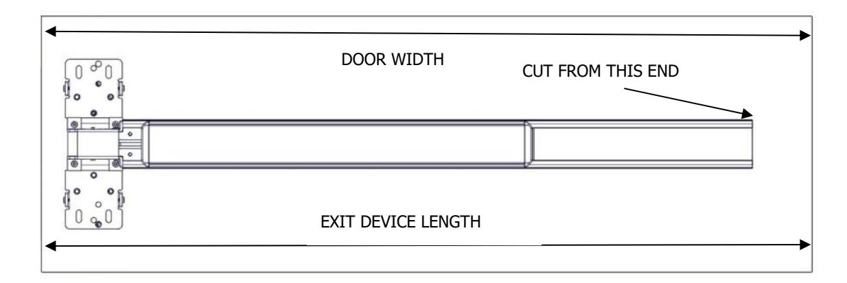
| DOOR WIDTH RANGE FOR EXIT DEVICES | ||
|---|---|---|
| 36" MODEL | 30"-36" DOOR WIDTH | |
| 48" MODEL | 36"-48" DOOR WIDTH | |
2. PREPARE DOOR
The Hager Exit device is designed to fit a door and frame prepared for a Mortise Lock per ANSI/BHMA A156.115-2016. The holes and cutouts specifically for the Hager Mortise Lock Exit Device are shown in the template T-ED01545 and in the Door Preparation Drawing S-ED01546. See www.hagerco.com for additional information.
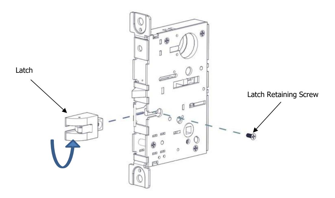
3. SET LOCK HANDING
Lock supplied as Left Hand Reverse from factory. To change handing of the lock body, remove the latch retaining screw. Slide the latch out of the lock, rotate the latch 180 degrees and slide it back into the lock. Reinstall latch retaining screw.
Rev 6, Rev Date: 12/12/24 Page 3 of 10

4. SET OUTSIDE HANDING OF LOCK CASE (MB AND MC TRIM ONLY)
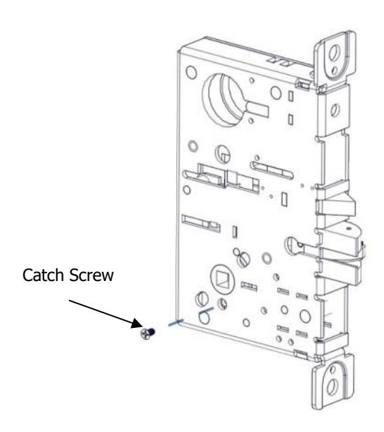
Skip this step for MN and MD trim. There is a catch screw on each side of the lock body. For MB and MC trim a catch screw must be removed on the PULL side of the lock body. The catch screw must stay in the PUSH side of the lock body.
5. SET HUB (MB AND MC FUNCTIONS ONLY)
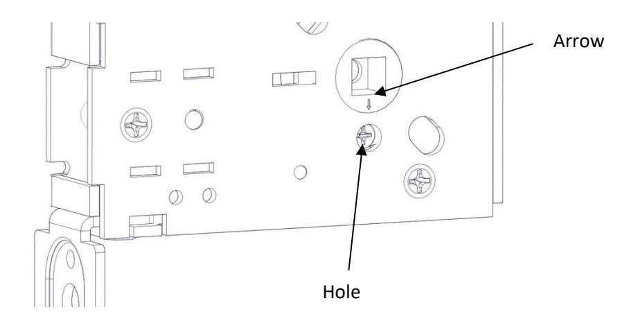
Check the hub of the lock case to make sure the arrow is pointing downwards toward the hole underneath it. If it is not in this position adjust it by rotating the hub until the arrow points down. This can be done by inserting the handing pin in the hub and turning it with a pair of pliers.
Rev 6, Rev Date: 12/12/24 Page 4 of 10

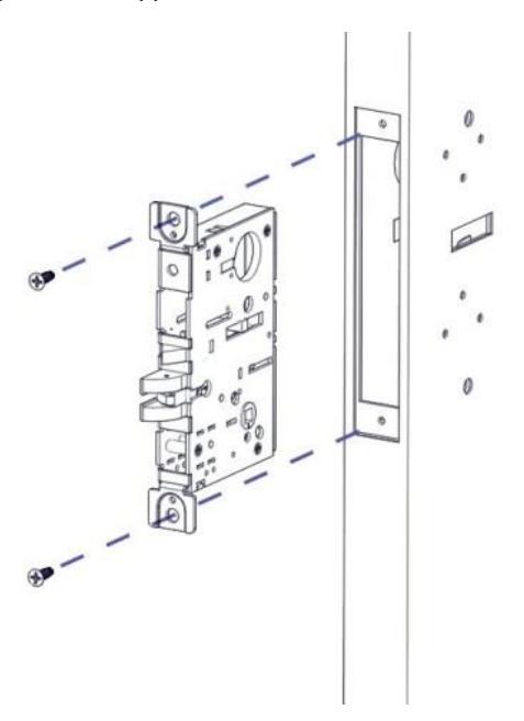
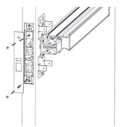
6. INSTALL LOCK TO DOOR
Install the lock in the door using the two supplied Wood/Metal combo screw.
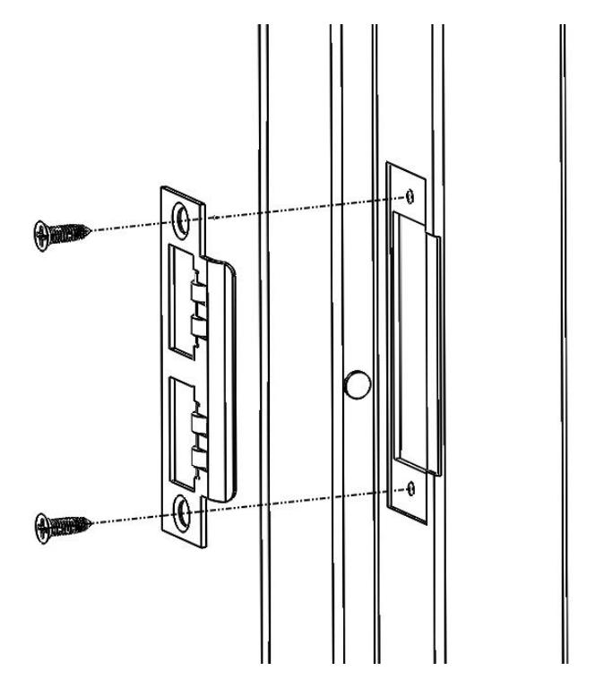
7. INSTALL THE STRIKE IN THE FRAME
Install the strike in the frame using the supplied #12 Wood/Metal Combination Screws.
Rev 6, Rev Date: 12/12/24 Page 5 of 10

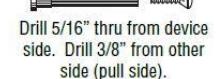
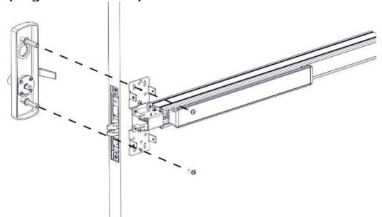
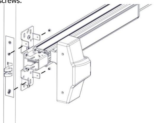
8. INSTALL EXIT DEVICE (METAL DOORS ONLY)
Remove the chassis cover from the exit device. Put the exit device up against the door. Make sure the Latch Finger on the exit device is inserted into the slot on the door and the mortise lock body and does not rub on the edges of the cutouts. Attach the exit device to the door with the supplied ¼-20 x 3/8" Screws. Note: this is an optional step for convenience only and is not possible with wood doors.
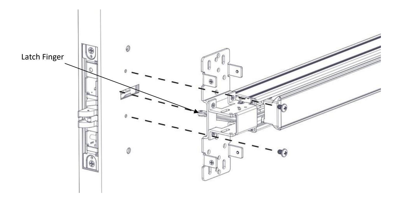
Rev 6, Rev Date: 12/12/24 Page 6 of 10

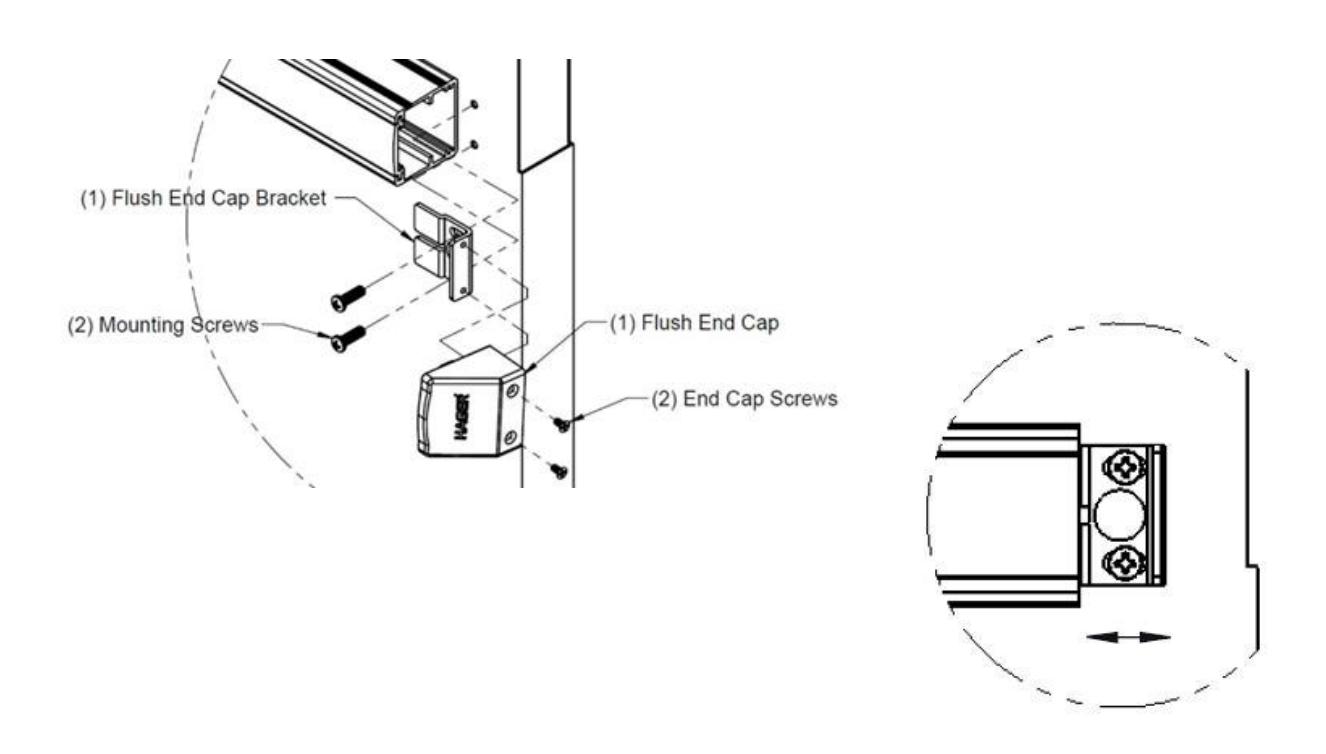
9. INSTALL END CAP
Remove the flush end cap from the flush end cap bracket. Mark hole locations by holding flush end cap bracket up against door and device. Be sure exit device is level before inserting the flush end cap bracket into the device. Mark and drill/tap holes. Install flush end cap bracket and flush end cap using supplied screws. If the flush end cap is not flush with the exit device, remove flush end cap and adjust the mounting screws and the flush end cap bracket as needed.
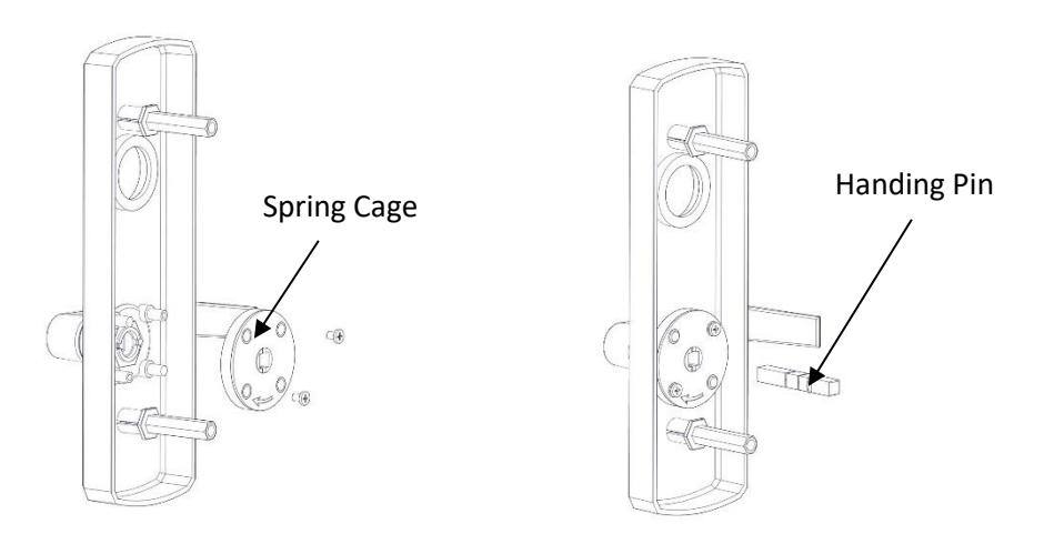
10. HAND TRIM (MB AND MC TRIM ONLY)
Make sure the handle is oriented to the side of the escutcheon that corresponds with the door handing. Make sure the spring cage is oriented so the arrow is pointing in the direction of the desired handle rotation. If it is not oriented properly, remove the two screws and rotate the spring cage 180 degrees and reinstall the screws. Install the handing pin.
Rev 6, Rev Date: 12/12/24 Page 7 of 10

11. HAND TRIM (MN AND MD FUNCTIONS ONLY)
For handing the MN and MD trim there is no spring cage. Position the handle in the proper orientation and install the handing pin.
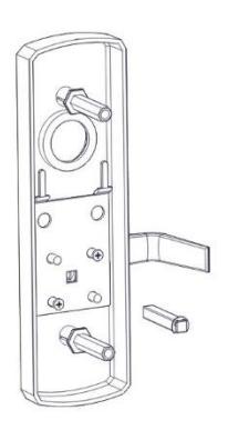
12. INSTALL TRIM
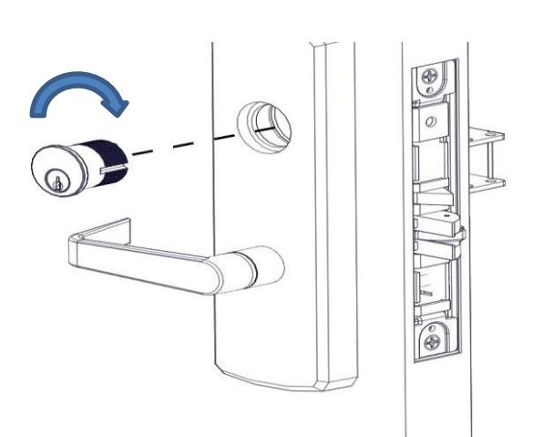
Install the trim on the pull side of the door insuring that the handing pin is properly inserted into the lock body. The handing pin only interacts with the lock body for the MC and MB functions. Use the supplied screws to bolt the trim to the door through the exit device chassis. If installing mortise cylinder do not fully tighten screws yet.
13. INSTALL MORTISE CYLINDER (MC AND MN TRIM ONLY)
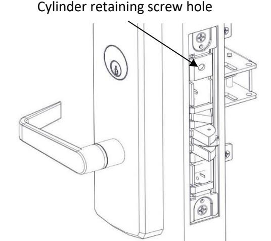
Loosen the cylinder retaining screw to allow the cylinder to be threaded into the lock case by inserting a screw driver with a #2 tip in the hole on the mortise lock body. Install the mortise cylinder in the trim. Screw the cylinder into the lock body. The keyway must end up on the bottom of the cylinder housing. Secure the cylinder by tightening the retaining screw. A 1-5/8" long cylinder is required for these functions. Fully tighten mounting screws from previous step.
Rev 6, Rev Date: 12/12/24 Page 8 of 10

14. INSTALL CYLINDER (NO TRIM – NL FUNCTION ONLY)
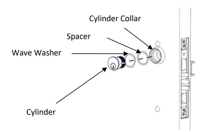
The Night Latch function can be used with a cylinder only or cylinder by optional pull. Loosen the cylinder retaining screw to allow the cylinder to be threaded into the lock case. This is done by inserting a screw driver with a #2 tip in the hole on the mortise lock body. Insert the wave washer, spacer and cylinder collar (7/16") over the cylinder. Screw the cylinder into the lock body. The keyway must end up on the bottom of the cylinder housing. Secure the cylinder by tightening the retaining screw.
15. INSTALL COVERS
Install the armor front with the supplied screws.
Install the Exit Device Head Cover using the supplied screws.
Rev 6, Rev Date: 12/12/24 Page 9 of 10

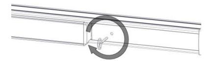
16. DOGGING DEVICE
For increased life of the device, dog the push bar down during high traffic periods of the day. Dogging is not available on fire-rated models.
Hex Wrench Dogging
To dog the device, press the push bar, insert the hex dogging wrench and turn clockwise 35 degrees. The push bar will remain depressed and the latch will stay retracted. To release the dogging, hold the push bar down, insert the hex dogging wrench, and turn counter-clockwise 35 degrees. The push bar will return to the up position and the latch will extend to lock the door.
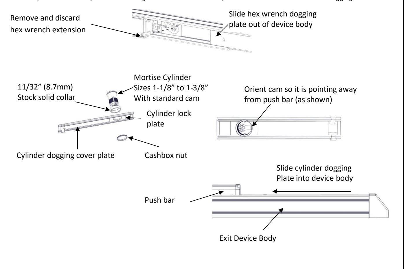
Cylinder Dogging
Required hardware for cylinder dogging includes one (1) mortise cylinder, lengths 1-1/8", 1-1/4" or 1-3/8" with a standard cam (0.723" [18mm] screw center to tip of cam); and one (1) Hager cylinder dogging kit (4926) which includes one (1) 11/32" [8.7mm] solid cylinder collar and cashbox nut. Remove and discard the hex wrench extension. The cylinder should be oriented so the cam is pointing away from the exit device push bar. Install the dogging cover plate with the cylinder and test the dogging. Depress the push bar, insert the key and turn the key clockwise to dog the device. Turn the key counter-clockwise to release the dogging.
Rev 6, Rev Date: 12/12/24 Page 10 of 10