Installation Instructions PD2090A
Open the original PDF document
View PDF3580 Willow Lane, Westlake Village, CA 91361-4921 • (805) 494-0622 • Fax: (805) 494-8861 www.sdcsecurity.com • E-mail: service@sdcsecurity.com
INSTALLATION INSTRUCTIONS MODEL PD2090A
READ THOROUGHLY BEFORE INSTALLING
CAUTION: This device for center hung doors only
INSTALLATION
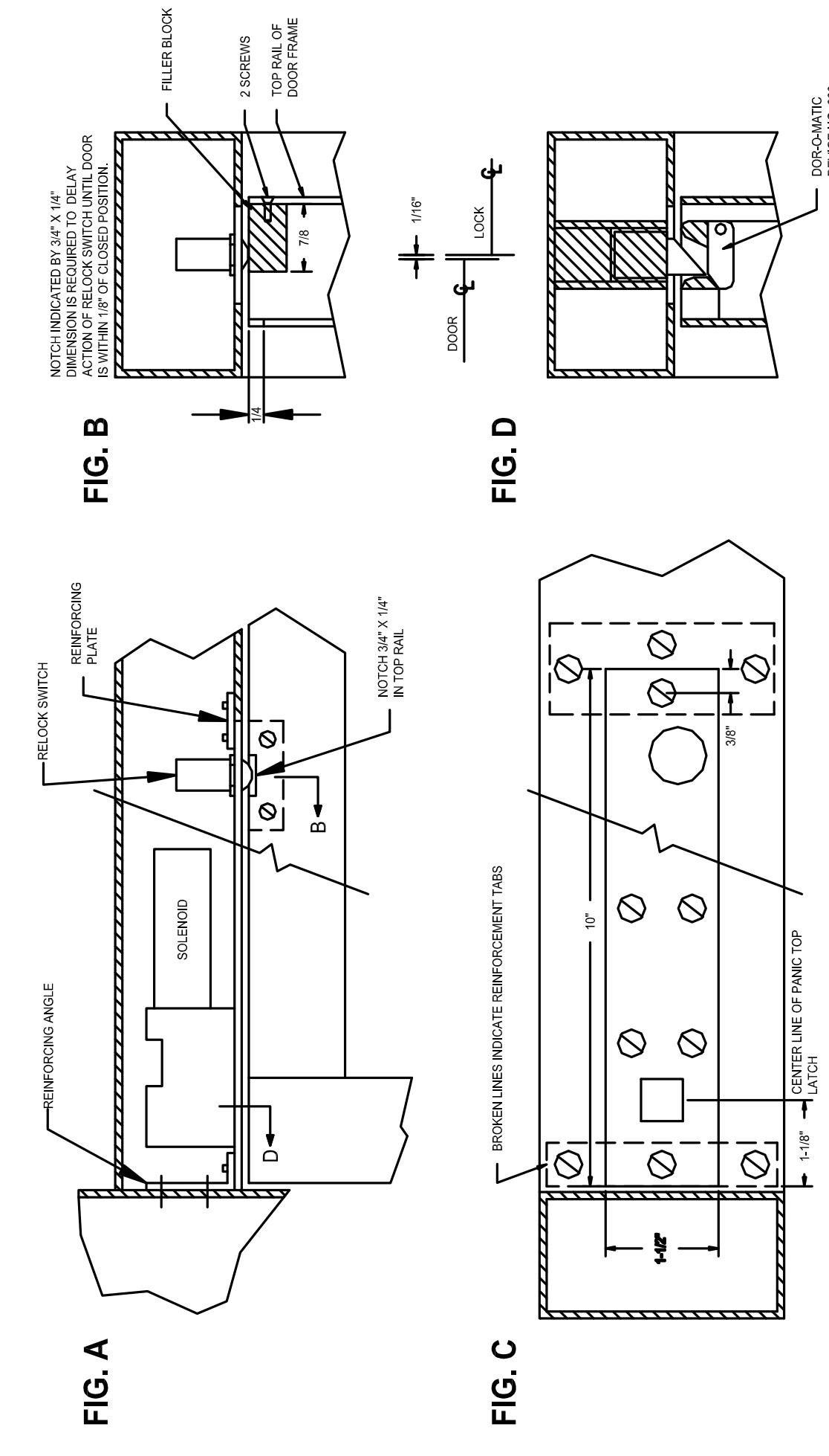
- Review the installations shown in figures A through D. Center line of panic device determines location of release.
- 2. The locking bolt will function as long as it enters the top latch bolt at some point. If it is not possible to line up on the panic device center line, a larger notch may have to be cut in the lock stile of the door to clear the lock latch bolt.
- 3. Remove bottom rod assembly.
- 4. A metal filler block must be placed in the top rail at the point of automatic relock switch. This block must be flush with the top of the door (required for the automatic relock switch). Because of variables, this filler block is not supplied by SDC. Notch inside top rail at relock switch.
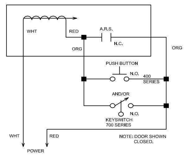
- 5. After reinforcement tabs have been installed, attach power leads as shown in wire diagram.
- 6. Insert lock into mortise and attach with machine screws provided.
FAIL SECURE (POWER UNLOCK)
| SPECIFICATIONS | TROUBLESHOOTING | ||
|---|---|---|---|
| Facepla | te: 10" x 1-1/2" x 1/8" | Problem | Solution |
|
uirements: 10" x 1-1/2" x 1-1/2"
d: Continuous Duty 2 Stage 24 VAC and 24 VDC available |
Top latch will not stand up. | Adjust top latch. | |
| Bolt: Be | Pull-in Coil – 57.6 watt/2.4 amp at 24VDC Holding Coil – 8.4 watt/.35 amp at 24VDC veled stainless steel 1/2" diameter x 1/2" throw | Bolt will not retract. | Check voltage at lock. Check rating of transformer. Check for cracks in switch on side of lock body. |
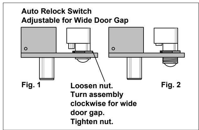
| В | Bolt position indicates bolt locked or unlocked 5 amp at 30VDC | Bolt projects too soon | . Adjust auto relock switch |
| D | Door position indicates door open or closed 5 amp at 30VDC | Bolt projects when door is open. | ARS has been bypassed. Check wiring. |