Installation Instructions GL160-GL260
Open the original PDF document
View PDF

INSTALLATION INSTRUCTIONS
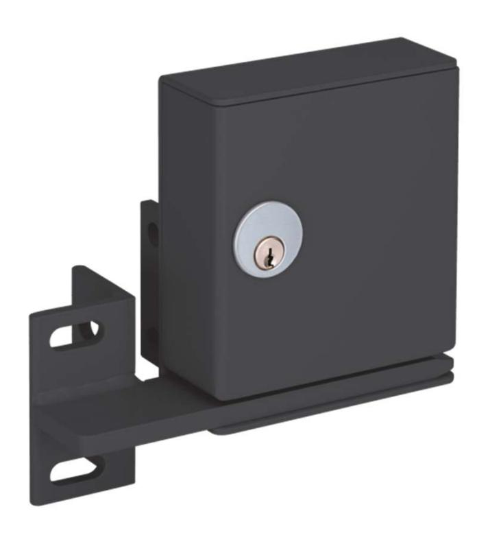
GL160 / GL260 GATELOCK
Available Models:
GL 160Al Fail-Safe
GL 260AH Fail-Secure
GL 163Al Fail-Safe, Built in Key Switch
GL 263AH Fail-Secure, Built in Key Switch
GL 260MRA Fail-Secure, Mechanical Release
Lock Operation:
The Lock has an adjustable automatic relock switch (ARS standard) that keeps the bolt retracted until the gate is in a closed position. A Bolt Position Switch (BPS, optional) monitors the lock and unlock position of the bolt. A gate position switch (DPS, optional) is also available to monitor whether a gate is opened or closed.
Specifications:
Dimensions: W 5" x H 6-1/8" x D 2"
Material: Steel
Finish: Black
Solenoid: Continuous Duty
Bolt Throw: 5/8"
Bolt Dia: 5/8"
Dual Voltage: 900mA @ 12 VDC
450mA @ 24 VDC
ARS: 3A @ 30 VDC
BPS: 3A @ 250 VAC
DPS: 3A @ 30 VDC
Key Switch: 10A @ 28 VDC

CAUSTION: DO NO INSTALL LOCKING TONGUE ONTO LOCK UNTIL WIRING IS COMPLETE.
GL160A & GL260A – GATE LOCK MOUNTING
Use the lock housing as a template to mark the mounting holes onto the post. If the wiring will go through the post remove cover and mark the wiring hole before mounting. Use a 3/8" drill size to drill out all holes. Be sure to shim between the mounting brackets as required if the gate post is less than 3". See illustration 1 & 2.
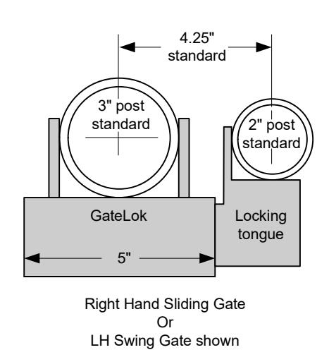
Determine the hand of gate and install the switches accordingly. See Illustration 3. The Illustration below gives an example of a LH swing and or a RH sliding gate install. To reverse the handing swap the position of the ARS and centering assembly to the opposite side of lock.
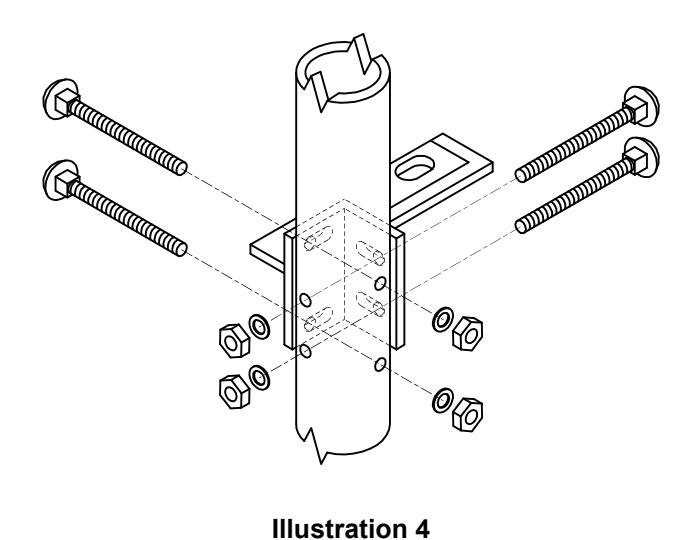
Before mounting the locking tongue verify that it is properly aligned within the gate lock opening. The locking tongue should be centered with the bolt and make contact with centering assembly and ARS. Once verified mark the mounting holes and drill use 3/8" drill size for all holes. See illustration 4.
Refer to page 4 of instructions for wiring information.
Test operation to verify that its functioning properly and re-install cover..
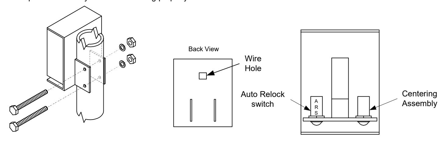
Illustration 1 Illustration 2 Illustration 3

GL163A & GL263A – BUILT IN KEY SWITCH
Install key cylinder per notes below
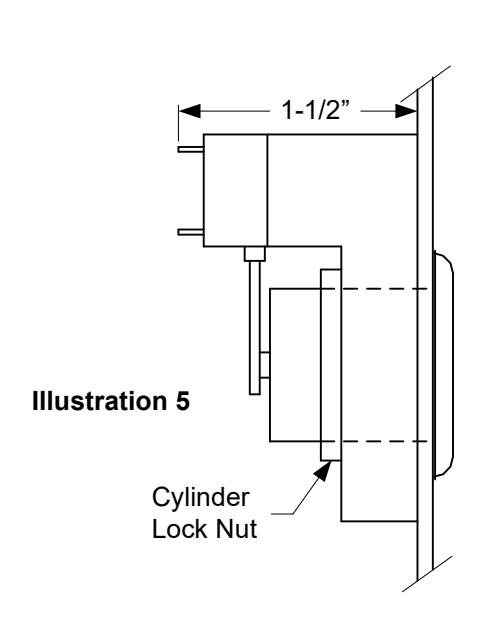
- a) Cylinder must be 1-1/8" mortise type with standard tailpiece. See illustrations 5
- b) Remove key and invert the tailpiece. See illustration 6.
Refer to page 4 of instructions for wiring information.
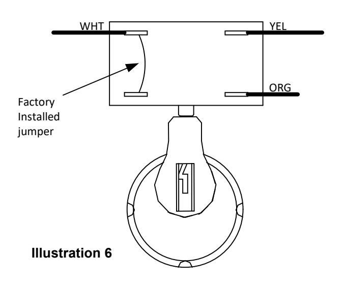
Note position of mortise cylinder & tailpiece relative to switch. Tailpiece must point up & depress switch button at all times with key removed.
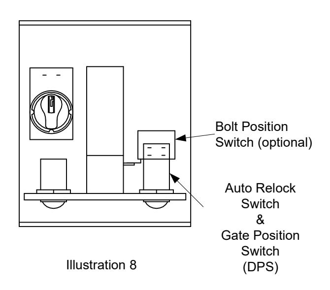
GL260MRA – MECHANICAL RELEASE
Install key cylinder per notes below
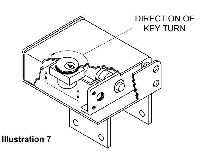
- a) Cylinder must be 1-1/8" mortise type with standard tailpiece. See illustrations 7
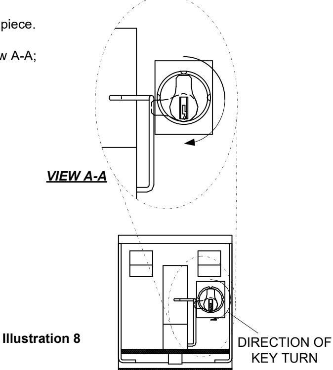
- b) Tailpiece must contact retraction arm as shown in View A-A; See illustration 8.
Page 3
Refer to page 4 of instructions for wiring.

WIRING REFERENCE
GL160A Typical wiring
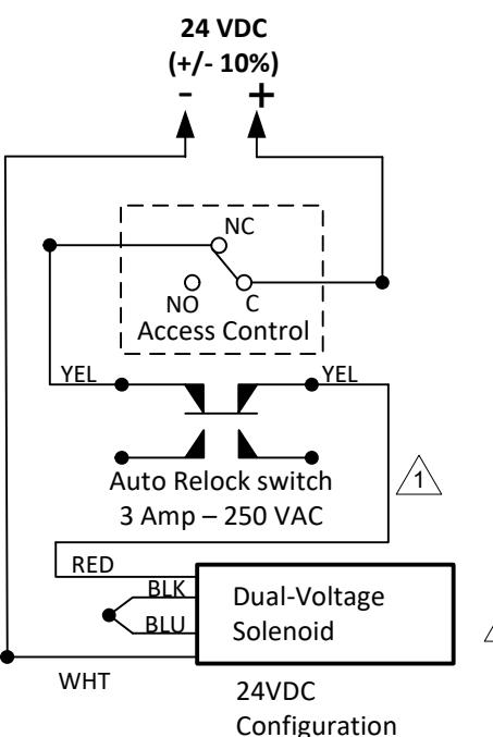
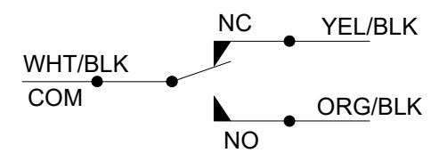
Auto Relock switch wiring shown with tongue engaged inside lock
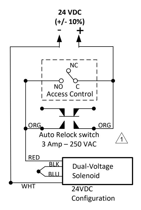
GL260A/260MRA Typical wiring
GL163A Typical wiring
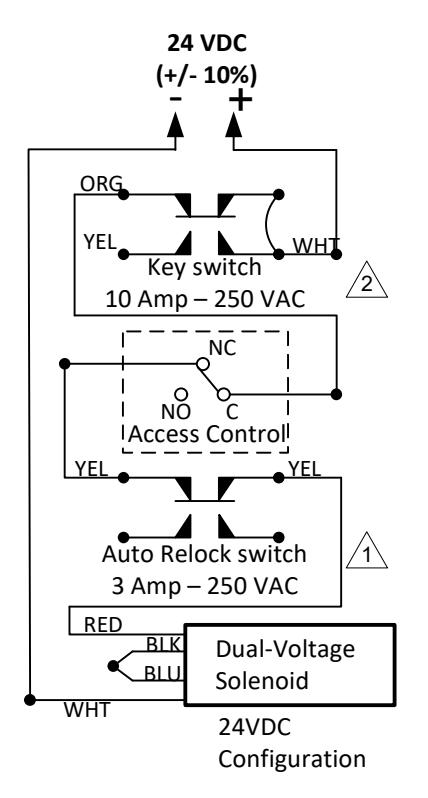
Auto Relock switch wiring shown with tongue engaged inside lock
Key switch wiring shown with tailpiece depressing switch
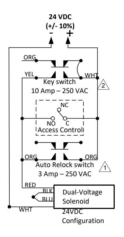
GL263A Typical wiring

OPTIONALMONITORING WIRING REFERENCE
260 BPS Wiring
Shown when Bolt is retracted
160 BPS Wiring
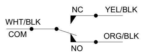
Shown when Bolt is retracted
DPS Wiring
Shown when tongue is inserted