Installation Instructions For 281 Door Closers With O10, H10, SSO Arms
Open the original PDF document
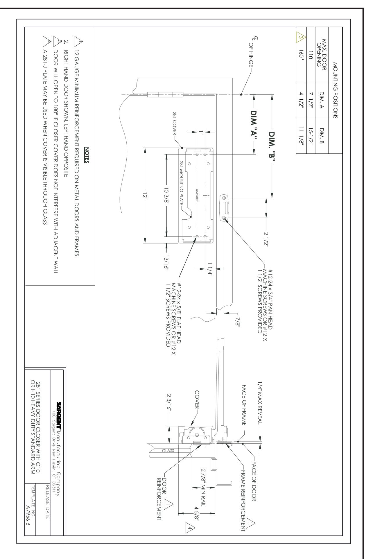
View PDF281 DOOR CLOSERS WITH O10, H10 & SSO ARMS INSTALLATION INSTRUCTIONS
281 SERIES ADJUSTABLE FROM SIZE 1 THRU 6
CAUTION: FAILURE TO INSTALL OR ADJUST PROPERLY MAY RESULT IN INJURY OR DAMAGE. FOR ASSISTANCE, CALL SARGENT AT 1-800-727-5477.
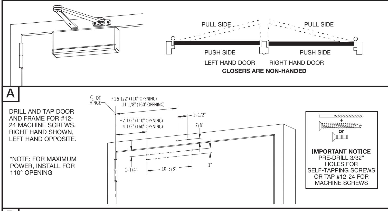
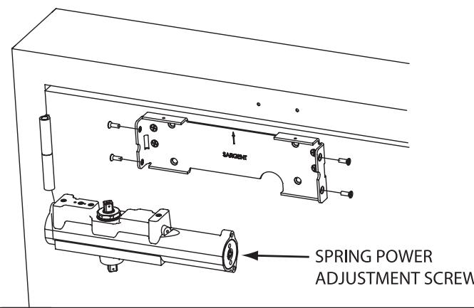
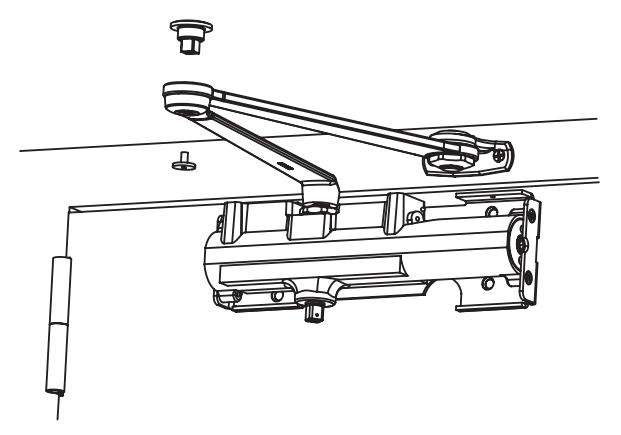
B INSTALL MOUNTING BRACKET WITH ARROW POINTING UP FOR BOTH RH & LH DOORS. MOUNT CLOSER WITH SPRING ADJUSTING SCREW AWAY FROM HINGE. SEE PAGE 2 FOR THRU BOLT INFO.
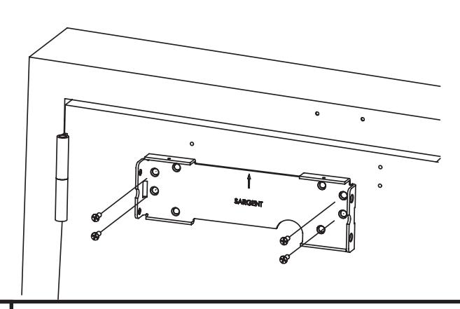
RIGHT HAND SHOWN
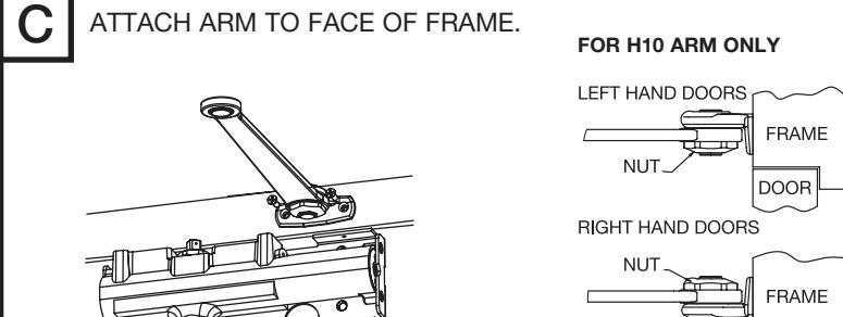
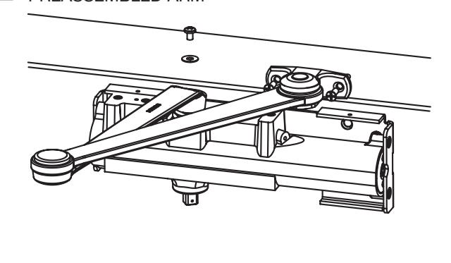
ALTERNATE: PREASSEMBLE ARM PRIOR TO ATTACHING TO STOP. C1
Copyright © 2012, 2014, Sargent Manufacturing Company, an ASSA ABLOY Group company. All rights reserved. Reproduction in whole or in part without the express written permission of Sargent Manufacturing Company is prohibited.
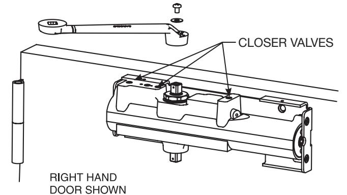
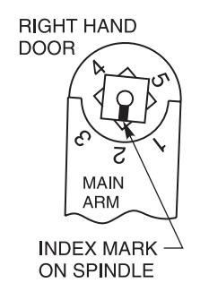
* WARNING: IF NOT PROPERLY INDEXED, DOOR !! CLOSER WILL NOT FUNCTION PROPERLY. !!
ALTERNATE METHOD FOR ATTACHING PREASSEMBLED ARM
E A. INSTALL PIVOT AS SHOWN B. USE SCREW TO SECURE PIVOT AND ARMS AS SHOWN
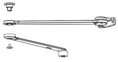
ACCESSORIES
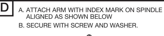
D1
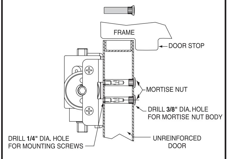
OPTIONAL: USE MORTISE NUTS (#4TB) WHEN THRU-BOLTING IS REQUIRED
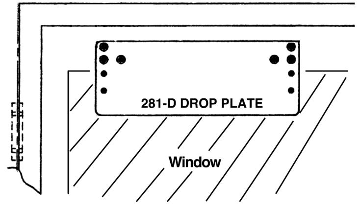
281 DROP PLATE USED WITH NARROW TOP RAILS.
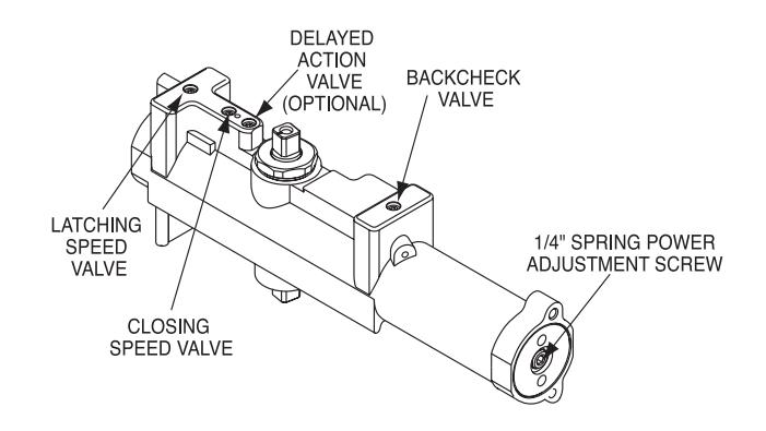
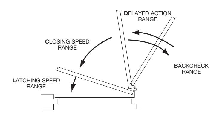
FINAL ADJUSTMENT AND REGULATING PROCEDURES
- F
- · Adjust Door speed, and Latching speed valves to achieve the desired closing time. Recommend 6 seconds minimum from 90° to the closed position.
- · If Backcheck is required, adjust valve to achieve a slight cushioning effect. Auxiliary stop required
- · If closer is equipped with Delayed Action, regulate valve to achieve the desired delay.

USE 1/8" HEX WRENCH TO ADJUST VALVES
G Adjust Closing power to the minimum required to reliably close and latch door
- · If door is hard to open, decrease power slightly
- · If door does not latch, increase power as required
- · Use the chart below as a starting point
Doors adjusted with high closing power to overcome strong draft conditions may exceed ADA standards
| + | - |
|---|---|
|
INCREASE
POWER |
|

ADJUST CLOSING POWER WITH A 1/4" HEX WRENCH
| SPRING POWER ADJUSTMENT GUIDELINES | |||
|---|---|---|---|
|
DOOR WIDTH
(INCHES) |
EXTERIOR DOORS | *INTERIOR DOORS | |
| 24-30 | Turn screw 2-7 | Turn screw 1-5 | |
| 30-36 | Turn screw 7-11 | Turn screw 3-6 | |
| 36-42 | Turn screw 11-15 |
FACTORY
SET |
|
| 42-48 | Turn screw 15-17 | Turn screw 8 & up | |
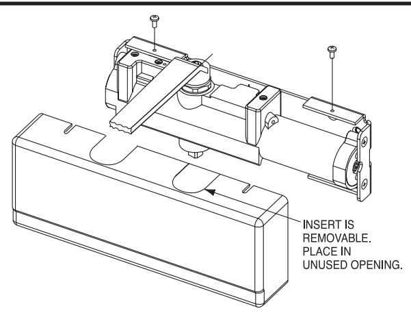
H INSTALL COVER WITH TWO SCREWS AS SHOWN. SSP INCLUDES HANDED METAL COVER (NOT SHOWN) AND 6 LOBE SECURITY SCREWS.

Copyright © 2012, 2014, Sargent Manufacturing Company, an ASSA ABLOY Group company. All rights reserved. Reproduction in whole or in part without the express written permission of Sargent Manufacturing Company is prohibited.
A7921C
in door opening solutions ASSA ABLOY, the global leader
ASSA ABLOY