Installation Instructions 482AA9-484AA9 INGRESS-REX TOUCH PANEL
Open the original PDF document
View PDF

INSTALLATION INSTRUCTIONS
482AA9 / 484AA9 INGRESS-REX TOUCH PANEL 9" x 6" PUSH TO OPEN
DESCRIPTION
"Knowing Act" automatic door control with contoured profile.
Specified in:
MasterFormat <sup>™</sup> 1995: Section 08 710 DOOR HARDWARE
MasterFormat<sup>™</sup> 2004: Section 08 7120 AUTOMATIC DOOR CONTROLS
DIMENSIONS
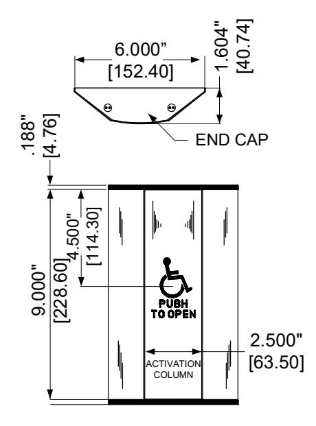
Overall: 9" height x 6" wide x 1-1/2" deep [229 x 152 x 38mm]
Center activation column: 9" x 2-1/2" [229 x 64mm]
MATERIALS:
Anodized Aluminum extrusion; Alloy 6063 T5. Typical thickness: 3/32" [2.4mm]
FINISHES
Anodized Aluminum: Clear;
Dark Bronze
ACTIVATION
Maximum horizontal movement of activation column; less than 1/4" (6mm) Maximum horizontal force to activate: 283 grams at all points on column
WALL MOUNTING HEIGHT
48" max to top of touch panel recommended. Considerations should be given to existing conditions.
CONTACT RATING
482AA9 – SPDT, Momentary, 15 A @ 125 / 250 VAC; 2A @ 48VDC 484AA9 – DPDT, Momentary, 15 A @ 125 / 250 VAC
SUPPLIED HARDWARE
- (4) Ribbed Drywall anchors
- (4) Lag screw masonry anchors
- (4) 1-1/4" slotted anchor screws
- (4) 1/4-20 Stainless flathead machine screws
- (2) Wire nuts
Touch Panel Mounting Instructions
Touch Panel is shipped fully assembled!
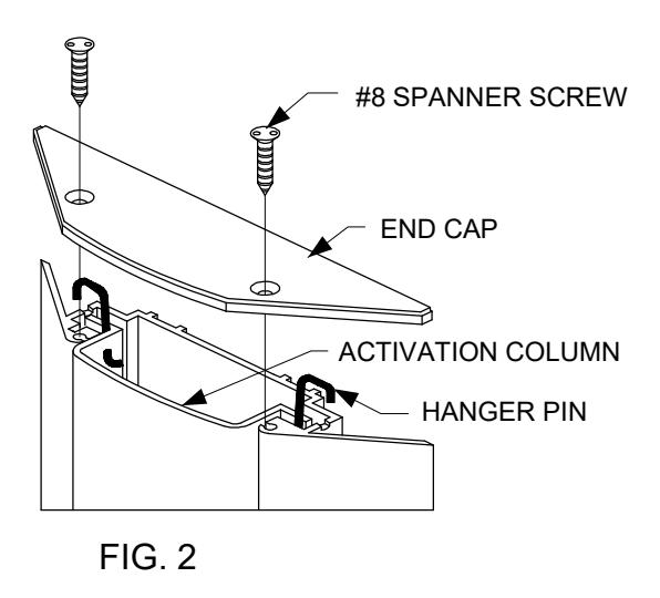
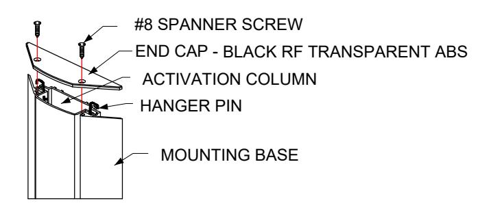
- 1. Remove Spanner screws from cap. NOTE:- SPECIAL TOOL NEEDED #8 Spanner screwdriver bit. Slide the ACTIVATION column out from the SWITCH BASE for base mounting (see FIG. 2).
- 2. NOTE: This unit is not designed to mount to any junction box. Use the enclosed hardware to mount directly to a vertical surface.
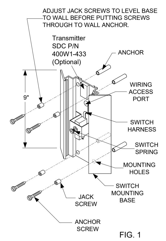
- 3. <u>For Wall Mount:</u> Position the MOUNTING BASE at the required location. Mark the locations of the MOUNTING HOLES. Install the appropriate supplied ANCHORS into wall. Adjust JACK SCREWS to prevent the MOUNTING BASE from conforming to irregularities in the wall. Install the supplied ANCHOR SCREWS through the JACK SCREWS and MOUNTING BASE into the ANCHORS. (see FIG. 1).
4. WIRING OPTIONS:
<u>Hard-Wired:</u> Using supplied wire nuts, connect the wires from the switch harness to field wiring.
<u>Wireless:</u> Using supplied wire nuts, connect the wires from the switch harness to TRANSMITTER activation wires. Use double sided tape (supplied with transmitter) to secure TRANSMITTER to the upper portion of the MOUNTING BASE as shown (see FIG. 1).
- 5. Slide the ACTIVATION column back into the MOUNTING BASE. Compress the SWITCH SPRING as the ACTIVATION COLUMN passes the SWITCH SPRING. The HANGER PINS should rest in the slots at the top of the MOUNTING BASE (see FIG. 2).
- 6. Position END CAP onto the top of the MOUNTING BASE. Attach with the previously removed spanner security screws (see FIG. 2).