Installation Instructions 482A4U SQUARE PUSH PLATE SWITCH
Open the original PDF document
View PDF

INSTALLATION INSTRUCTIONS 482A4U SQUARE PUSH PLATE SWITCH, PUSH TO OPEN, BLUE INFILL – 4-1/2" SPDT
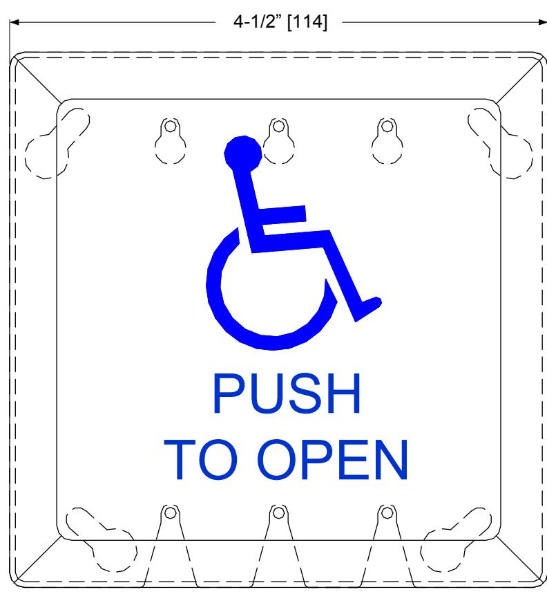
BLUE INFILL
Specifications
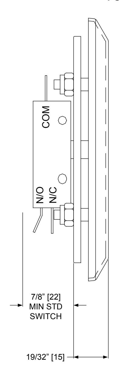
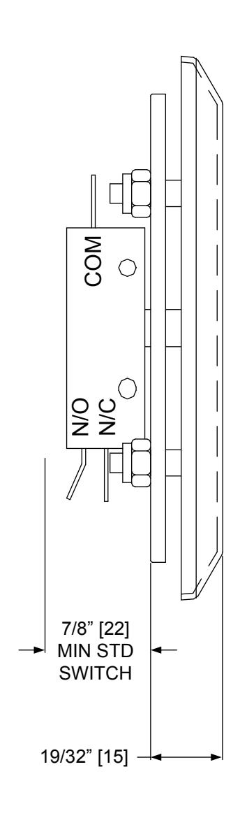
Physical Size: 4-1/2"sq x 1-15/32"D
Switch mounts to a Single Gang (2"x4") or Double Gang (4"x4")
electrical box
Contact Type: SPDT Momentary Contact Rating: 2 Amp @48VDC
15 Amp @125/250VAC

INSTALLATION INSTRUCTIONS 482A4RU ROUND PUSH PLATE SWITCH, PUSH TO OPEN – 4-1/2" SPDT
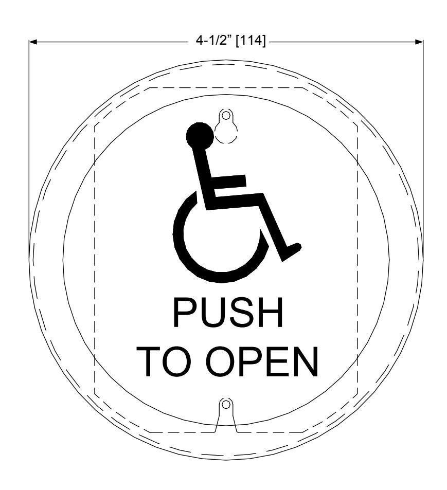
Specifications
Physical Size: 4-1/2" Dia x 1-15/32"D
Switch mounts to a Single Gang (2"x4") or Double Gang (4"x4")
electrical box
Contact Type: SPDT
Contact Rating: 2 Amp @48VDC
15 Amp @125/250VAC

INSTALLATION INSTRUCTIONS 480-4SBB / 480-6SBB SURFACE MOUNT BOX w/BATTERY COMPARTMENT
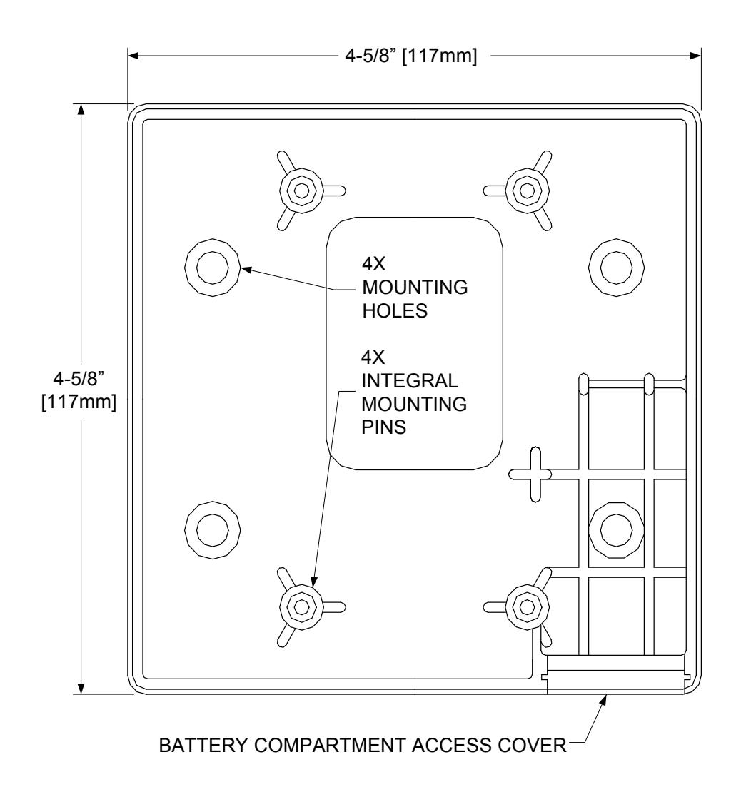
BLACK ABS MATERIAL BOX EQUIPPED FOR WIRED OR WIRELESS APPLICATION. USED WITH 4-1/2" SQ. AND 6" SQ. SWITCHES
480-4SSB / 480-6SBB MOUNTING INSTRUCTIONS
(HARD WIRED and WIRELESS)
1) Break out the battery compartment access cover from the back of the box and install it into the open area in the side wall located at the bottom of the box, as it will hang on the wall. When the access cover is in the closed position, the slot in the cover will face out and be closest to the switch.
When installed correctly, the door slides smoothly and will be held in place by the mounting plate.
2) Use appropriate screws (not supplied) to mount the box to the wall surface at the 4 open mounting hole positions.
If needed, drill a small weep hole in the bottom of the box (as it hangs) to allow moisture to evaporate.
- 3) If you are using a wireless transmitter, attach the transmitter to the back of the box using the included double sided tape. Connect the battery terminals to the battery and install into the battery compartment. Program the transmitter to match the receiver.
- 4) For either Hard-wired or Wireless setups, connect the lead wires to the switch at the
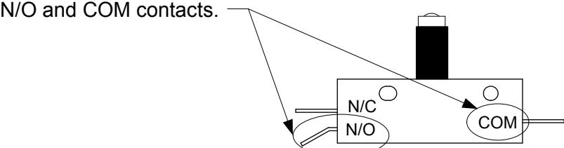
5) Fit the 6-32 x 5/8" socket cap screws from the switch parts bag into the 4 integral mounting pins located at the
upper and lower 2-gang positions.
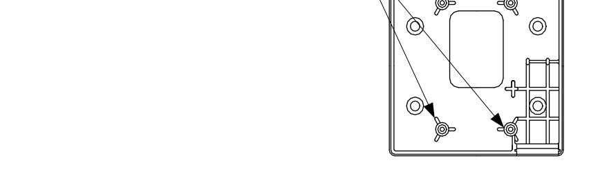
6) Hang the wall switch onto the socket cap screws and tighten down with the allen wrenches provided in the parts bag or with the handle grip allen wrenches. Alternate the tightening of the screws a few turns at a time each from the top to bottom.

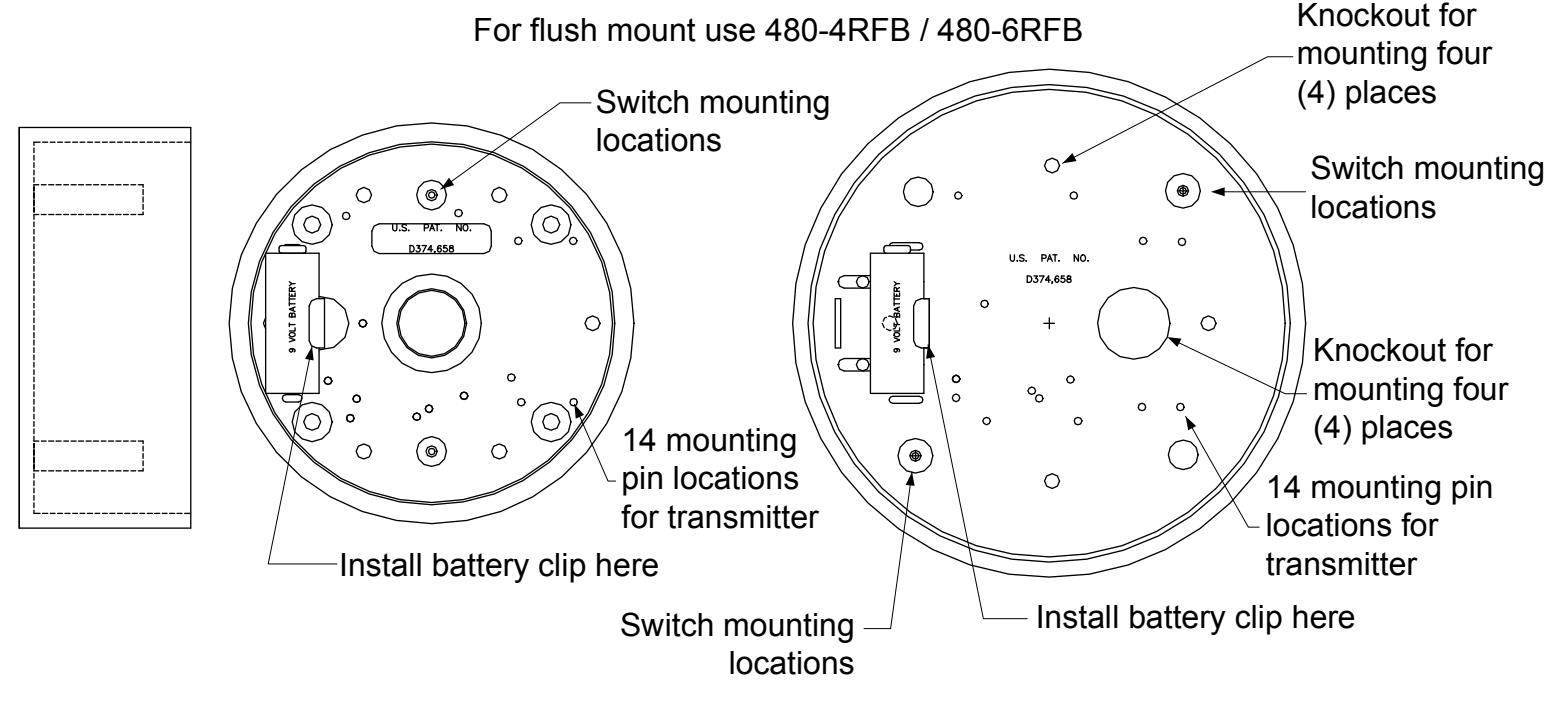
INSTALLATION INSTRUCTIONS 480-4RFB / 480-4RSB & 480-6RFB / 480-6RSB SURFACE/FLUSH MOUNT BOX FOR 4-1/2" & 6" DIAMETER SWITCHES
CROSS SECTIONAL VIEWS
Parts included with mounting boxes : >Black ABS surface or flush mount box >Transmitter mounting pins >9V battery mounting clip >Mounting instructions >Weather resistant gasket (optional)
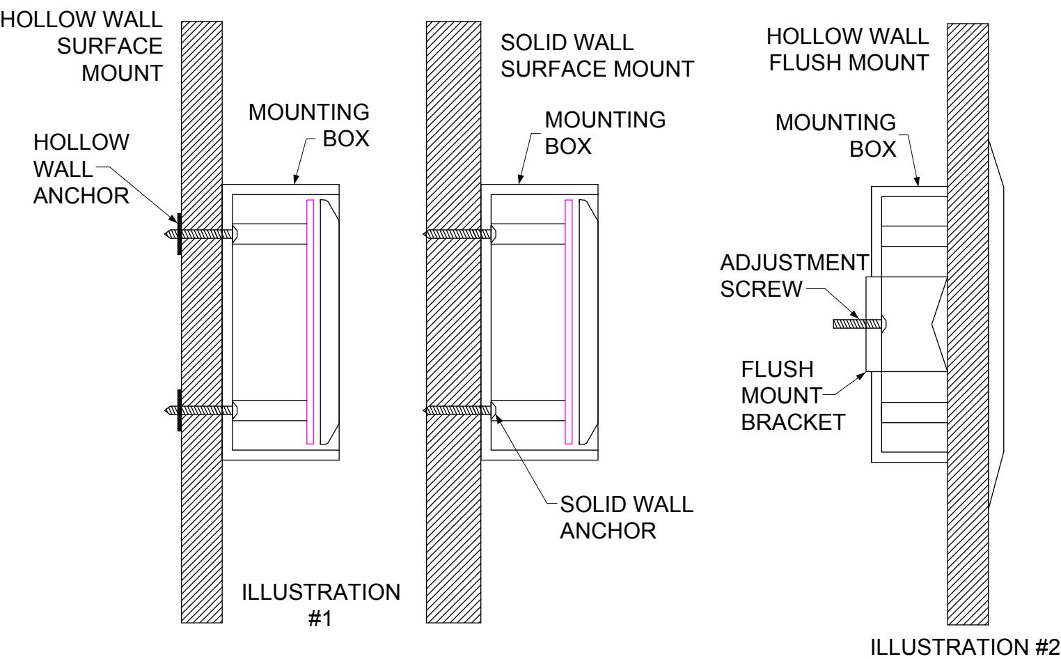
480-4RSB & 480-6RSB SURFACE MOUNT: Hollow Wall or Solid Wall (illustration #1) 1] Drill pilot holes in mounting box (placement indications are in box). 2] Drill pilot holes in mounting surface. 3] Insert appropriate fastener (screw, toggle, etc.) through box and into mounting surface; tighten. 4] Complete installation of switch.
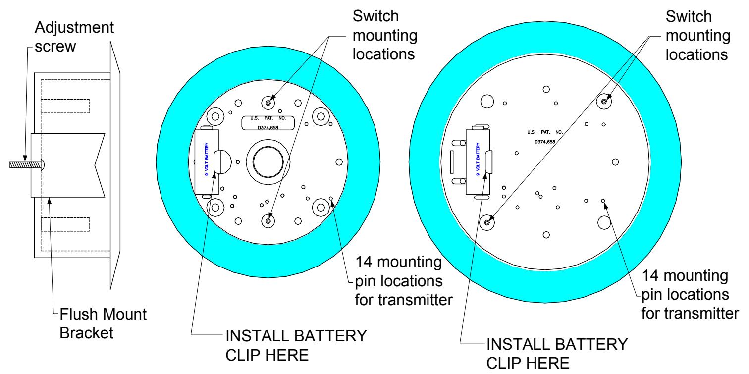
480-4RFB & 480-6RFB FLUSH MOUNT: Hollow Wall ONLY (illustration #2) 1] Cut access hole into mounting surface: 5-1/2" dia. for 4-1/2" round box – 6-1/2" dia. for 6" round box. 2] Insert box into the hole. 3] Utilize the two phillips head screws to tighten silver hanger to the mounting surface. 4] Complete installation of the switch.
480-4RSB
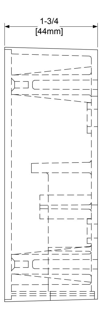
5" Diameter x 2-1/8" Height (127mm x 55mm) 1-7/8" inside depth (48mm) Used with 4-1/2" round switches
480-6RSB
6-7/16"" Diameter x 2-1/8" Height (164mm x 55mm) 1-7/8" inside depth (48mm) Used with 6" round switches
- Surface mount black ABS material for wireless or hard-wired applications
- Repositionable mounting pins for transmitter placement
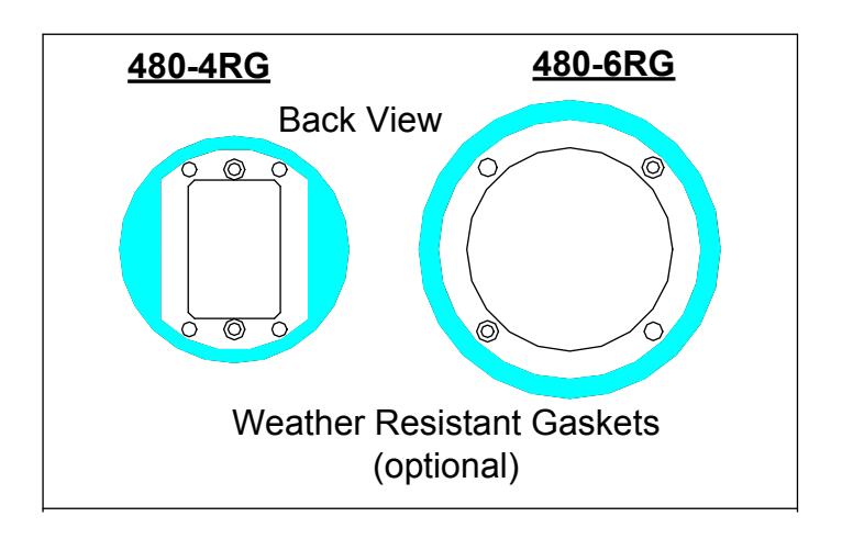
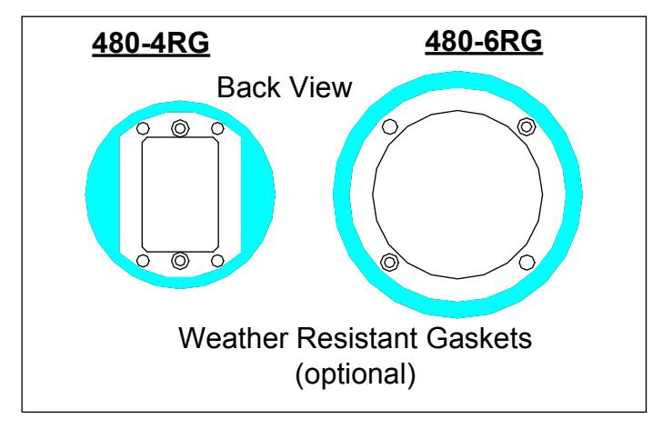
- Weather resistant gasket (optional)
480-4RG used with 480-4RSB 480-6RG used with 480-6RSB
480-4RFB
6-3/8" Diameter x 2-1/8" Height (162mm x 55mm) 1-7/8" inside depth (48mm) Used with 4-1/2" round switches
480-6RFB
7-3/4" Diameter x 2-1/8" Height (197mm x 55mm) 1-7/8" inside depth (48mm) Used with 6" round switches
For surface mount use 480-4RSB / 480-6RSB
- Mounting bracket for hollow walls.
- Flush mount black ABS material for wireless or hard-wired applications; Wireless use requires RF Transparent walls.
- Repositionable mounting pins for transmitter placement.
- Weather resistant gasket (optional)
480-4RG used with 480-4RSB 480-6RG used with 480-6RSB

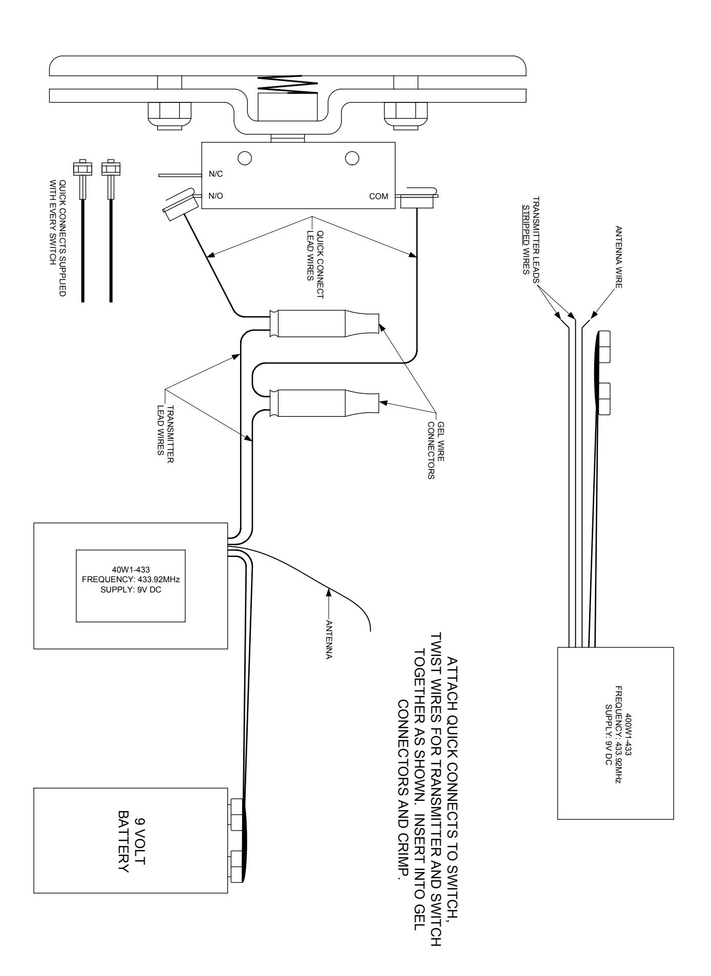
PROGRAMMING INSTRUCTIONS 400W1-433 Transmitter, 433 Frequency
Programming -
NOTE: The 400W1-433 Transmitter is only compatible with the 400RC433 Receiver.
- 1) Attach battery to the 400W1-433 transmitter.
- 2) Push P1 on the Receiver 1 channel 433 until you hear a beep, then touch the black flagged wires together and hold until the receiver beeps again. The 400W1-433 will then be programmed into the receiver.
9 VOLT BATTERY FREQUENCY: 433.22 MHz ANTENNA Problem Solution
Troubleshooting -
- A) The receiver does not receive the transmitter signal Change the battery and the transmitter LED will not light up.
B) Operation is very weak or sporadic Change the battery or check the wiring on the transmitter or receiver to make sure wires are secure and not pinched.
3) Attach quick connects to switch. Twist wires from the switch and transmitter together and insert into the gel connector and crimp.
Technical Specifications -
Operating Frequency – 433 MHz Battery - 9 Volt DC Operating Temperature - -20 C -100 F
Type – 433TSPWIK FCC IS: SU433TSP4K
This device complies with Part 15 of the FCC Rules.
Operation is subject to the following two conditions:
- 1) This device may not cause harmful interference, and
- 2) This device must accept interference received, including interference that may cause undesired operation.

PROGRAMMING INSTRUCTIONS for the 400RC433 RECEIVER, ONE CHANNEL
REC 1 CHAN 433
1 - DESCRIPTION
The Nano Receiver is designed to control automatic closing systems and anti-burglar systems, thanks to it's very high security coding system (KeeLoq Hopping code). R
The operating frequency is among European harmonized frequencies; the product fully complies with the EMC European Regulations (CA).
The code sent by the transmitter changes at every activation, avoiding any scanning and copying risk. A special algorithm allows for synchronization of transmitter and receiver.
The receiver has 1 output relay with NO contacts, and can be connected to many types of mechanics (gate, garage door, rolling shutters,, awnings, anti-burglar appliances, etc.).
All the receivers of this range can store into the EEPROM a serial number, a manufacturer key and a synchronization algorithm of more transmitters.
The programming can be done in a self-learning mode by means of one button.
The housing protection allows indoor installations. This appliance fully complies with the European Regulations89/336/EEC, 73/23/EEC, EN 60950-1 and FCC Part 15.
2 – TECHNICAL SPECIFICATIONS
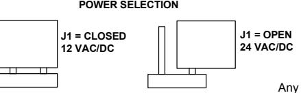
Receiver type Superheterodyne Carrier frequency 433.92 MHz Local oscillator frequency 6.6128 MHz Demodulation AM/ASK Local oscillator VCO / PLL Channel width > 25 KHz Intermediate frequency 10.7 MHz Input sensitivity -115 dBm Local oscillator spurious emissions < -57dBm Input load 50 Ohm Power supply 12 / 24 VAC/DC Max applicable power 12 VA Relay number 1 Contacts C-NO
Memory capacity 85 user codes
TX security code Rolling code
Max code combination number 2
Operating Temperature -20 / +70 deg C
Housing protection IP2X
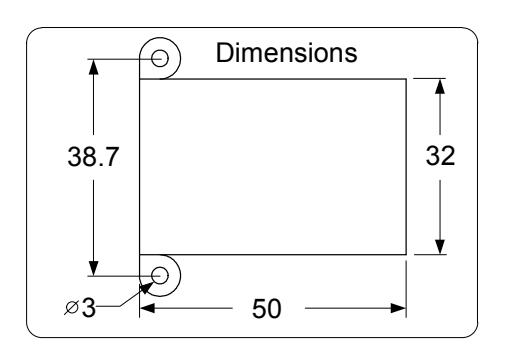
Overall dimensions (mm) 50 x 32 x 20
3 – LAYOUT AND CONNECTIONS
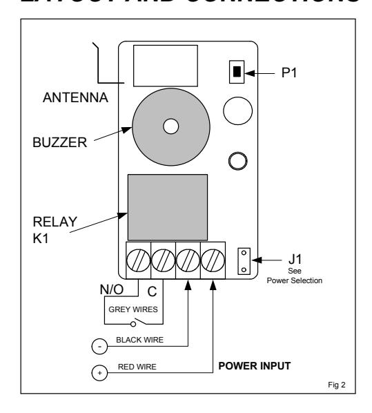
Any suggestions or comments to this instruction or product are welcome. Please contact us through our website or email engineer@sdcsecurity.com
4 – TRANSMITTER PROGRAMMING
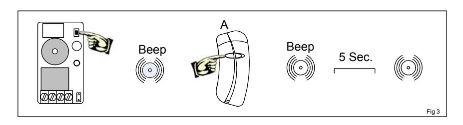
4.1 Using P1
- 1) Keep P1 pressed down until the buzzer emits a short beep (Fig 3);
- 2) Push the key of the transmitter to program, and very the beep of the receiver;
- 3) At this point, the receiver waits for more transmitters – 5 seconds after the last transmitter is programmed, the receiver makes a beep and the procedure ends.
4.1 Using P1
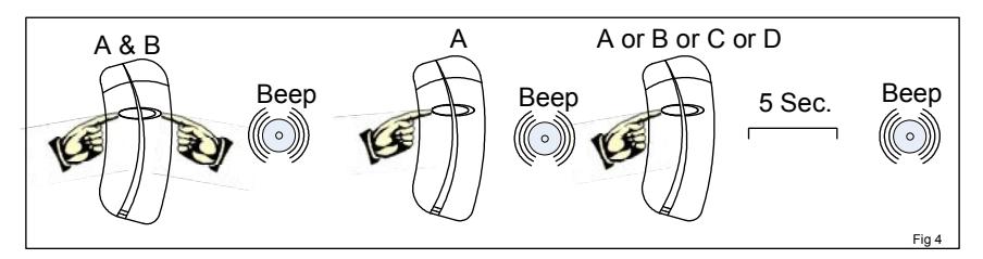
With this procedure it is possible to program the transmitters without accessing P1 (Fig 4)
- 1) Push simultaneously the keys A & B of the transmitter until it beeps.
- 2) Release and push the A key until the next beep of the buzzer (memory opening);
- 3) Release A and push the key of the transmitter to program (A or B) until the beep of the buzzer (memory closing).


If the memory is full when you try to program a new transmitter, the buzzer beeps three times.
6 – MEMORY ERASURE
6.1 Single Transmitter
- 1) Keep P1 pressed down until the buzzer beeps, then release it.
- 2) Push the key of the transmitter to delete until the buzzer beeps.
6.2 Full Memory Erasure
- 1) Push P1 until the buzzer beeps, then release it.
- 2) Release P1 and push it again until the buzzer beeps 3 times. At this point, the memory has been completely erased.
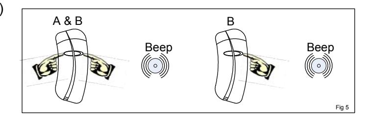
7 – ENABLING/DISABLING THE ACTIVATION BEEP
To program the receiver to make a beep
at each relay activation, follow this procedure: (Fig 5)
- 1) Simultaneously press the A & B keys of a previously programmed transmitter.
- 2) Release and press the B key of the transmitter to enable the beep. to disable the beep, repeat the above procedure.