Installation Instructions 2000 Series
Open the original PDF document
View PDF

SECURITY DOOR CONTROLS
801 Avenida Acaso, Camarillo, Ca. 93012 • (805) 494-0622 • Fax: (805) 494-8861 www.sdcsecurity.com • E-mail: service@sdcsecurity.com
2000 SERIES INSTALLATION INSTRUCTIONS
OVERHEAD INSTALLATION HORIZONTAL
- 1. Examine the top rail of the door for the most suitable location for the strike. Mark the door for the end of the strike closest to the lock stile, and make a corresponding mark on the header to line up with the first mark.
- 2. Locate centerline of door thickness on the header and attach adhesive cut-out template to header. Lining it up with marks, center punch the tab-mounting screw locations and counter-sink for #10 screw. Saw or rout out the cut-out area.
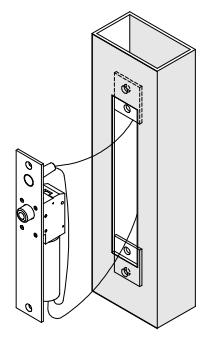
SIDE JAMB INSTALLATION VERTICAL
- 3. Examine the lock stile jamb for the point nearest the center of the door height, with space available for the lock and strike. Mark the door stile horizontal for the top end of the strike and make a corresponding mark on the jamb.
- 4. Locate centerline of door thickness on the jamb and attach cut-out template to jamb, lining up the top of the cut-out with the horizontal mark on the jamb. Center punch the tab mounting screw locations and counter-sink for #10 screw. Saw or rout out the cut-out 1-1/2" X 8".
- 5. Attach the mounting tabs inside frame.
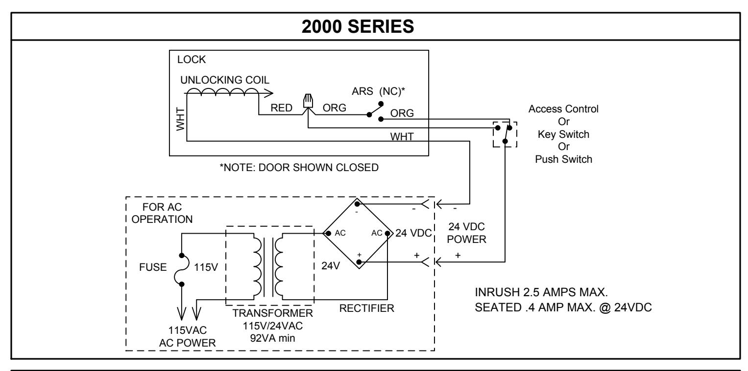
- 6. Attach power supply leads to lock leads as shown. Handle the lock carefully; do not hang it by the wire leads. Insert wires into the header cavity carefully so they do not interfere with proper locating of the lock in the cut-out.
- 7. Insert lock. Horizontally, the bolt end is nearest the lock stile. Vertically, the bolt must be at the top end of the cut-out. Secure with #10-32 machine screw.
- 8. Using strike for a template, mark screw hole location and drill holes for screws supplied. Mortise as required. Attach strike.
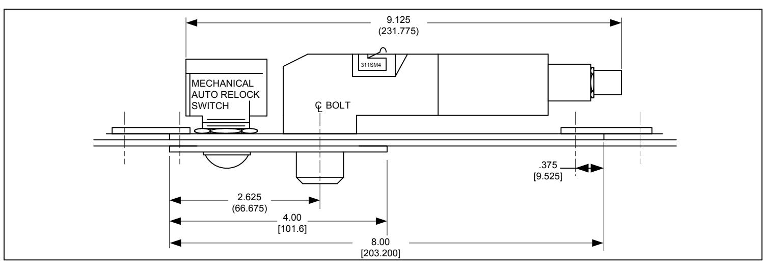
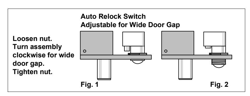
- 9. The automatic relock switch (A) is set for 1/8" clearance between the top of the door and the transom bar or head jamb. Any additional gap may be compensated for by loosening the lock nut and turning the assembly clockwise until proper adjustment is reached. Be sure to tighten lock nut when adjustment is satisfactory.
Easy installation or servicing
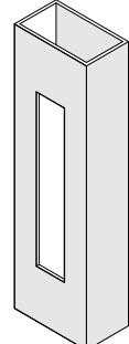
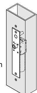
All Space Saver locks are easily installed in any existing entrance merely by mortising out a cut-out, attaching the wiring, inserting the lock, and bolting it into position with two attaching tabs. Cutting studs is no longer a problem or expense.
-
1. Mortise cut-out in tube for face plate (fits flush with surface of tube).
- 2. Position screws for attaching tabs, drill holes, attach tabs.
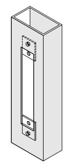
- 3. Connect wiring to lock.
- 4. Slide lock into position, attach to tabs.
| SPECIFICATIONS | MAGNETIC BOLT POSITION SENSOR | |||
|---|---|---|---|---|
| Face plate: 8" x 1-1/2" x 1/8" | for wood door frames: 11-1/2" x 1-3/4" X 1/8" | -B SPDT | Indicates bolt locked or unlocked | .25 amp |
|
I.D. Requirements: 2090A: 10" x 1-1/2" x 1-1/2"
Solenoid: Continuous duty, fail secure type INRUSH 2.5 AMPS MAX. SEATED .4 AMP MAX. @ 24VDC |
RED = N/C
WHT = COM BLU = N/O |
BPS polarity shown with bolt retracted. | ||
| MECHANICAL DOOR POSITION SENSOR | ||||
|
Strike: M-mortise 4" x 1-1/2" x 1/8"
Bolt: 3/4" dia. stainless steel, 3/4" throw |
-D SPDT
5A@125VAC (Resistive) |
Indicates door open or closed | ||
| TROUBLE SHOOTING | RED = N/C | |||
|
Problem
Solution Bolt will not retract of strike |
Check voltage and alignment |
WHT = COM
BLU = N/O |
DPS polarity shown with door closed | |
| Bolt does not project | Strike misaligned | |||
NOTE: Electrical boxes are available for most SDC mortise locks. We recommend electrical boxes whenever locks are installed in wood frames. (Request template).