Installation Instructions 180-280
Open the original PDF document
View PDF

801 Avenida Acaso, Camarillo, Ca. 93012 • (805) 494-0622 • www.sdcsecurity.com • E-mail: service@sdcsecurity.com
INSTALLATION INSTRUCTIONS/TEMPLATE 180/280 SERIES ELECTRIC LOCKS
1. Determine the appropriate mounting configuration for your application (Header mount or Top-jamb or Side-jamb mount.
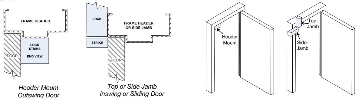
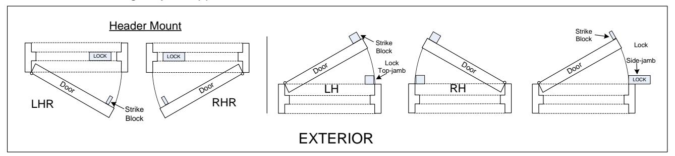
2. Determine the handing for your application.
3. Remove the lock housing cover. Based on the mounting information determined on steps 1 & 2 above, adjust the Auto Relock Switch (ARS) in the bolt chamber bracket as described below.
| Mounting Configuration | Auto-Relock Switch Orientation |
|---|---|
| Header Mounted - LHR | Perpendicular to the mounting plate |
| Header Mounted - RHR | Perpendicular to the mounting plate |
| Top Jamb or Side Jamb - Swing (LH or RH) | Perpendicular to the mounting plate |
| Top Jamb - Sliding to Left* | Parallel to the mounting plate |
| Top Jamb - Sliding to Right* | Parallel to the mounting plate |
| *Tob Jamb Sliding Door requires a positive stop | |
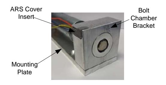
3a. Remove the ARS insert and install the ARS switch as shown. Replace the plastic insert.
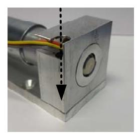
Perpendicular to Mounting Plate
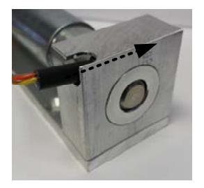
Parallel to Mounting Plate
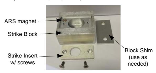
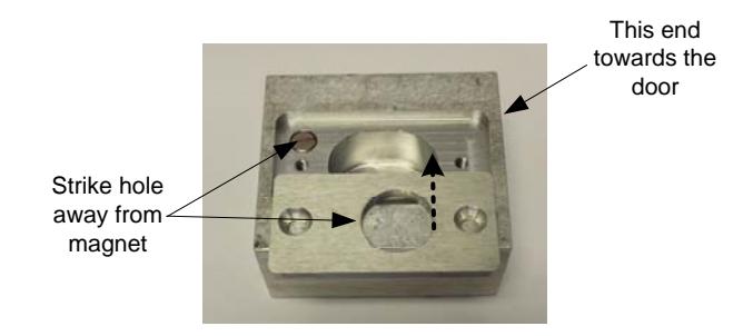
4. Configure the strike block assembly (Choose 4a, 4b, or 4c):
4b. For Header-mounted, LHR
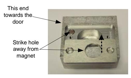
4a. For Header-mounted, RHR
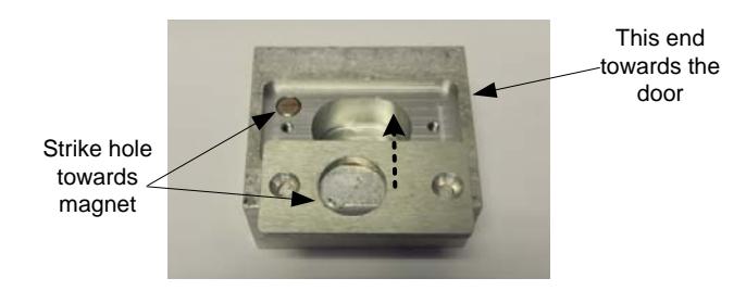
4c. For Top Jamb (swing or slide) or Side Jamb
-
5. Mark and drill as follows: Holes 1, 2, 3, and 4 for #10 sheet metal screws or 10-32 x 1/2 machine screws. Hole 8 – 3/8" diameter for wire.
- Block strike: Holes 5 and 6 or 12 and 13 for 1/4 20 machine screw.
- 6. Tap holes as required.
- 7. Mount lock and strike block.
- 8. Attach power leads as shown on Page 3. When bolt is thrown, check alignment of bolt and strike. There should be no binding on the bolt. Leading part of strike block should be 1/8" away from the lock ( 1/8" is maximum distance) . If this is correct, tighten mounting screws.
- 9. Check lock operation for any last adjustments.
- 10. Re-install housing cover.
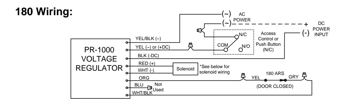
LOCK WIRING
NOTE: The SDC PR-1000 Power Regulator module is included with the 180/280 bolt lock, and is required for optimal solenoid lifespan. Installing the PR-1000 reduces the power consumption of the bolt locks after activation of the lock, allowing for a heat reduction to the bolt lock.
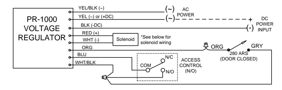
280 Wiring:
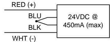
Solenoid Voltage Configuration:
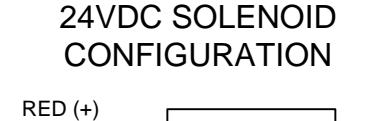
12VDC SOLENOID CONFIGURATION
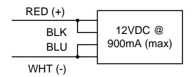
ELECTRICAL DATA: Dual Voltage (180/280) 12VDC@ .9 Amp (max.) 24VDC@ .45 Amp (max.) Continuous Duty
SPECIFICATIONS
DIMENSIONS: Lock 2" x 2" x 6"; Strike Block 2" x 2-1/4" x 1"
FINISH: US28 standard (dark duranodic optional) BOLT: 180/280 series - 1/2" diameter, 1/2" throw SOLENOID: 180, power to lock; 280, power to unlock
PR1000 Input Voltage: 12/24 VDC/AC (+/-10%) DC voltage is recommended for optimal performance