Installation Instructions 1200 SERIES
Open the original PDF document
View PDF

801 Avenida Acaso, Camarillo, Ca. 93012 • (805) 494-0622 • www.sdcsecurity.com • E-mail: service@sdcsecurity.com
1200 SERIES INSTALLATION INSTRUCTIONS
OVERHEAD INSTALLATION HORIZONTAL
- 1. Examine the top rail of the door for the most suitable location for the strike plate. Mark the door for the end of the strike closest to the lock stile, and make a corresponding mark on the header to line up with the first mark.
- 2. Locate center line of door thickness on the header and attach adhesive cut out template to header. Lining it up with marks, center punch the tab-mounting screw locations and counter-sink for #10 screw. Saw or rout out the cutout area. Continue to step 5.
SIDEJAMB INSTALLATION VERTICAL
- 3. Examine the lock stile jamb for the point nearest the center of the door height, with space available for the lock and strike. Mark the door stile horizontal for the top end of the strike plate and make a corresponding mark on the jamb.
- 4. Locate center line of door thickness on the jamb and attach adhesive cutout template to jamb, lining up the the top of the cutout with the horizontal mark on the jamb. Center punch the tab mounting screw locations and counter sink for #10 screw. Saw or rout the frame cutout.
- 5. Attach the mounting tabs inside.
- 6. Attach power supply and access control leads to lock leads as shown on page 2. Handle the lock carefully; do not hang it by the wire leads. Insert wiring into the header cavity carefully so they do not interfere with proper locating of the lock in the cutout.
- 7. Insert lock. When installed overhead horizontally, the bolt end is nearest the lock stile. When installed vertically on the sidejamb, the bolt must be at the top end of the cutout. Secure with #10-32 machine screw.
- 8. Using strike plate as a template, mark screw hole location and drill holes for screws supplied. Mortise as required. Attach strike.
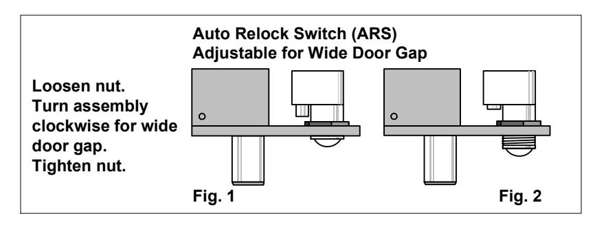
- 9. The Automatic Relock Switch (ARS) is set for 1/8" clearance between the top of the door and transom bar or head jamb. Any additional gap may be compensated for by loosening the lock nut and turning the switch assembly clockwise until proper adjustment is reached. Be sure to tighten lock nut when adjustment is satisfactory.
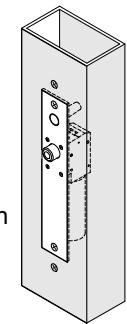
Easy installation or servicing
All Space Saver locks are easily installed in any existing entrance merely by mortising out a cut-out, attaching the wiring, inserting the lock, and bolting it into position with two attaching tabs. Cutting studs is no longer a problem or expense.
-
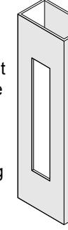
1. Mortise cut-out in tube for face plate (fits flush with surface of tube).
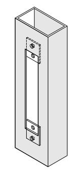
- 2. Position screws for attaching tabs, drill holes, attach tabs.
-
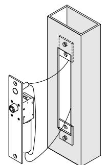
3. Connect wiring to lock.
- 4. Slide lock into position, attach to tabs.
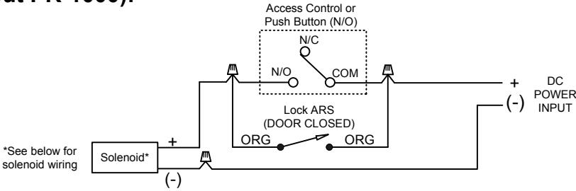
LOCK WIRING
NOTE: The SDC PR-1000 Power Regulator is included with the bolt lock. Although the solenoid is rated for continuous duty, continuously powering the solenoid will generate heat. Installing the PR-1000 reduces the power consumption of the bolt locks after activation of the lock, allowing for a heat reduction to the bolt lock, and increasing the life of the solenoid. DC voltage is recommended for improved heat reduction.
1291A (Without PR-1000):
1291A (Wiring w/ PR-1000; recommended):
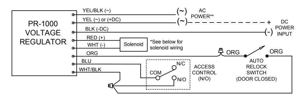
**AC Power requires the PR-1000
Solenoid Voltage Configuration:
24VDC SOLENOID CONFIGURATION

12VDC SOLENOID CONFIGURATION
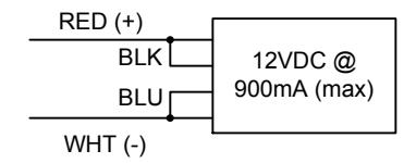
ELECTRICAL DATA: Dual Voltage Solenoid (1291A)
12VDC@ .9 Amp (max.) 24VDC@ .45 Amp (max.) Continuous Duty
PR1000 Input Voltage: 12/24 VDC/AC (+/-10%) DC voltage is recommended for optimal performance
TROUBLESHOOTING
Problem Bolt does not project Bolt projects but chatters Bolt will not retract Solution Check voltage and strike alignment. Voltage too low. Strike misaligned
| В | Indicates bolt locked or unlocked | 5 Watt |
|---|---|---|
| OPTIONAL DOOR POSITION SWITCH (DPS-MECHANICAL) | ||
| D | Indicates door opened or closed | 4A @ 30VDC (Resistive) |
|
RED=NC
WHT=COM BLU=N/O |
DPS polarity shown with door open BPS polarity shown with bolt retracted RED = N/C WHT = COM BLU = N/O | |
DPS/ BPS CONFIGURATION
OPTIONAL BOLT POSITION SENSOR (BPS-MAGNETIC)