Installation Instructio Addendum 8200-7900 Mortise Lock
Open the original PDF document
View PDFInstallation Instruction Addendum
8200 / 7900 Mortise Lock with Designer Lever

Trim Assembly Installation
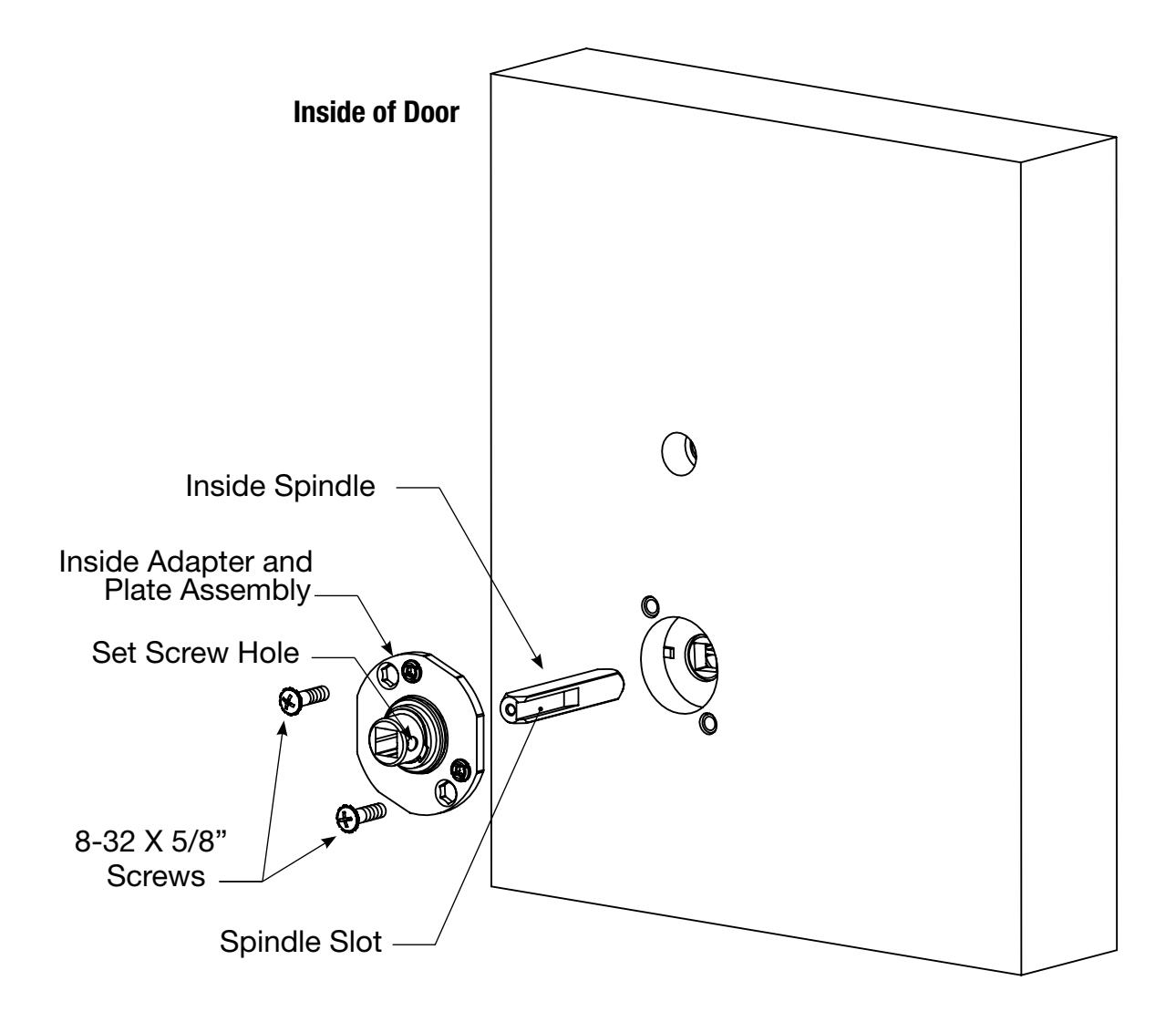
- 1. During assembly of the inside trim, insert inside spindle into square hole of mortise lock, with spindle slot directed away from the mortise lock body, and aligned with the set screw hole in the Inside adapter.
- 2. Slide inside adapter and plate assembly over spindle, and secure with (2) 8-32 X 5/8" Phillips oval head and lock washer machine screws.
Note: Ensure that the position of the set screw hole and spindle slot are oriented to match location of hole in the inside lever handle.